106-110 PE111163 PE10 02.10.2012 14:38 Uhr Seite 106 ... · The combined foaming and injection...
5
Physical Foaming Made Very Easy Thermoplastic Foam Injection Molding. Savings in weight and material, dimen- sional stability plus higher productivity are aspects that fire the imagination of de- velopers. All the more surprising is the fact that injection molding specialists have dealt with the physical foaming of thermoplastics rather hesitantly in the past. Especially in lightweight construction, the MuCell process offers great potential. 106 INJECTION MOLDING © Carl Hanser Verlag, Munich Kunststoffe international 10/2012 Physical foaming permits warp-free production of complex molded parts with very different wall thicknesses, as for this water pump housing ANDREAS HANDSCHKE JOCHEN MITZLER A s soon as the subject of foaming comes up, many experts sponta- neously think of reaction technol- ogy. Admittedly, this year is the 75th an- niversary of the discovery of poly- urethane. Far younger than that is ther- moplastic foam injection molding (FIM), which has only been known since the 1960’s. Without going into further detail about the wide range of properties and applications of the two very differ- ent material groups PUR and thermo- plastic foam, the lightweight construc- tion potential that is common to both materials must be mentioned. While nu- merous applications were found for polyurethanes, FIM failed to achieve comparable successes, although it is one of the oldest special plastics processing technology. The beginnings of foam injection molding go back to the 1950’s. At that time “experienced injection molders added a small pinch of baking powder (up to 0,05 %) to the granulate, if sink marks appeared on the molded product” [1]. Another effect, which was hardly noticed at the time, was the associated saving in weight. The foam structure, as well as the resulting lower density, only became in- teresting many years later, since new ma- terials and suitable propellants had to be developed first. Series production of the first thermo- plastic structural foam parts started in the early 70’s, initially with chemical propel- lants. Already at that time, KraussMaffei was attempting to develop a finer and de- fined foam structure [2, 3], and to pro- duce molded parts without sink marks and with densities between 0,3 and 0,6 g/cm 3 with reduced clamping forces. Hereby, the use of a physical propellant seemed to be most practicable, together with the so-called direct gassing as a vari- ant of FIM. The principle was based on introducing the foaming agent under high pressure directly into the melt-filled screw flights. Applications known from automakers at that time were decorated interior linings, housing parts, and elec- trical connectors. Because the propellant gases used were no longer permitted for Translated from Kunststoffe 10/2012, pp. 151–156 Article as PDF-File at www.kunststoffe- international.com; Document Number: PE111163
Transcript of 106-110 PE111163 PE10 02.10.2012 14:38 Uhr Seite 106 ... · The combined foaming and injection...

Physical Foaming
Made VeryEasy
Thermoplastic Foam Injection Molding. Savings in weight and material, dimen-
sional stability plus higher productivity are aspects that fire the imagination of de-
velopers. All the more surprising is the fact that injection molding specialists have
dealt with the physical foaming of thermoplastics rather hesitantly in the past.
Especially in lightweight construction, the MuCell process offers great potential.
106
I N J EC T I ON MOLD ING
© Carl Hanser Verlag, Munich Kunststoffe international 10/2012
Physical foaming permits warp-freeproduction of complex molded partswith very different wall thicknesses,
as for this water pump housing
ANDREAS HANDSCHKE
JOCHEN MITZLER
As soon as the subject of foamingcomes up, many experts sponta-neously think of reaction technol-
ogy. Admittedly, this year is the 75th an-niversary of the discovery of poly-urethane. Far younger than that is ther-moplastic foam injection molding(FIM), which has only been known sincethe 1960’s. Without going into furtherdetail about the wide range of propertiesand applications of the two very differ-ent material groups PUR and thermo-plastic foam, the lightweight construc-
tion potential that is common to bothmaterials must be mentioned. While nu-merous applications were found forpolyurethanes, FIM failed to achievecomparable successes, although it is oneof the oldest special plastics processingtechnology.
The beginnings of foam injectionmolding go back to the 1950’s. At thattime “experienced injection moldersadded a small pinch of baking powder (upto 0,05 %) to the granulate, if sink marksappeared on the molded product” [1].Another effect, which was hardly noticedat the time, was the associated saving inweight. The foam structure, as well as theresulting lower density, only became in-teresting many years later, since new ma-terials and suitable propellants had to bedeveloped first.
Series production of the first thermo-plastic structural foam parts started in theearly 70’s, initially with chemical propel-lants. Already at that time, KraussMaffeiwas attempting to develop a finer and de-fined foam structure [2, 3], and to pro-duce molded parts without sink marksand with densities between 0,3 and0,6 g/cm3 with reduced clamping forces.Hereby, the use of a physical propellantseemed to be most practicable, togetherwith the so-called direct gassing as a vari-ant of FIM. The principle was based onintroducing the foaming agent underhigh pressure directly into the melt-filledscrew flights. Applications known fromautomakers at that time were decoratedinterior linings, housing parts, and elec-trical connectors. Because the propellantgases used were no longer permitted for
Translated from Kunststoffe 10/2012, pp. 151–156Article as PDF-File at www.kunststoffe-international.com; Document Number: PE111163
106-110_PE111163_PE10 02.10.2012 14:38 Uhr Seite 106

107
I N J E C T I ON MOLD ING
>
Kunststoffe international 10/2012 www.kunststoffe-international.com
ecological reasons, the project was final-ly dropped in favor of the chemicalprocess.
Strategic Mistakes Corrected
The first breakthrough was made by Trex-el Inc., Wilmington, Massachusetts/USAat the end of the 1990’s with the MuCellprocess using modified and improvedtechnology. Originally invented at theMassachusetts Institute of Technology(MIT) in the late 80’s, the process was ini-tially aimed at extrusion. It was only at thebeginning of the year 2000 that interestwas focused on injection molding. How-ever, several strategic mistakes preventeda successful propagation of the process: Inaddition to the costs for the technicalequipment, Trexel demanded license feesfrom users, whereby the amount was de-termined annually, and was based onthroughput. Since the end of 2005, Trex-el no longer charges license fees, but thisimportant information has not yetreached all areas in the plastics industry.
Another hindrance was the marketingstrategy.Apart from the original focus onextrusion, Trexel initially failed to addressthe potential users and OEMs. The com-pany targeted plastics processors andmoldmakers, although experience showsthat these only have limited influence onthe project-related processing technolo-gy. Consequently, awareness of the newprocess was mainly restricted to a smallcircle of insiders. Meanwhile, Trexel haschanged their strategy, and has raised theinterest of users and OEMs [4].
As one of the first machine manufac-turers, KraussMaffei in Munich, Ger-many, has cooperated with Trexel fromthe start.Following the joint developmentof standardized equipment on the ma-chine side, KraussMaffei included com-plete MuCell system packages in theirproduct range early in 2001.
Plasticizing Unit With GasInjector
In simple terms, this type of physicalfoaming involves injection moldingwith gas charging. Prerequisite is a ful-ly automated injection molding ma-chine with screw position control andincreased injection volume. A plasticiz-ing unit with a specially designed screw
is the heart of the system. The gas is in-jected directly into the plastic melt inthe form of a super critical fluid (SCF),from which the screw produces a homo-geneous single-phase solution. A non-return valve prevents the gas/melt mix-ture expanding prematurely towards thefeed end, and the machine’s shut-offnozzle blocks the melt at the front end.Nitrogen or CO2 is used as propellant(Fig.1).
Important hereby is that the meltpressure in the plasticizing unit – andpossibly also in the hot runner system –may not fall below the critical SCF meltpressure during the entire cycle. This iswhy screw position control (“active backpressure”) is required, which also en-sures that the pressure is maintainedeven when the safety door is open. Forthe same reason, the machine is operat-ed with a needle valve nozzle, or in thecase of hot runner molds with a boltshut-off nozzle, whereby the nozzle con-tact force is reduced while the clampingunit is opening. In order to shift the pres-sure drop – and thereby the beginningof the foaming process – as far as possi-ble toward the end of the filling stage,and to ensure foaming at the end of theflow path, injection must be carried outquickly. Therefore, the machine musthave a high injection capacity.
As physical foaming agent, the gas re-duces the melt viscosity, which simplifiesfast injection. The pressure drop during
Fig. 1. Plant concept for the MuCell process: Also existing machines can be retrofitted easily. Since the end of 2005, users no longer need to pay license fees for applying this technology (photos: KraussMaffei)
KraussMaffei Technologies GmbHD-80997 MunichGermanyTEL + 49 89 8899-0> www.kraussmaffei.com
Contacti
Fig. 2. By means ofphysical foaming,this door lock hous-ing can be produced25 % faster (shortercycle times) and with30 % lower clampingforce (photo: Schröder
Kunststofftechnik)
106-110_PE111163_PE10 02.10.2012 14:39 Uhr Seite 107
108
I N J EC T I ON MOLD ING
© Carl Hanser Verlag, Munich Kunststoffe international 10/2012
injection into the cavity triggers the for-mation of gas bubbles, which cause themelt to be foamed. As opposed to chem-ical foaming, the MuCell process involvesa large number of finely distributed seeds.This fine distribution ensures the forma-tion of many small, equally sized andclosed cells with a diameter of less than100 µm. Within the cross-section of acomponent, a so-called integral foamstructure is created: a foamed core withlow density, enclosed in a thin, compactcovering layer with higher density. Al-though the surface is closed, it does notexhibit the quality of a compact injectedmolding.
Foaming The Melt CompensatesShrinkage
Foaming of the melt compensates forshrinkage at the mold wall. This permitsfoaming with a considerably less holdingpressure – even without holding pressurein the ideal case. Similarly, the internalmold pressure is significantly lower thanwith compact injection molding, andlower melt and mold temperatures can al-so be selected.
All of this – no or very less holdingpressure, and lower cooling requirements– reduces the required clamping force by30 to 50 %, and cuts the cycle time byabout 20 % (Figs. 2 and 3). Moreover, themoldings exhibit very low warpage. Inmost cases, they are completely free ofsink marks and air traps. The foamingprocess is also effective at the end of theflow path, where the holding pressure isoften obstructed by freezing of the plas-
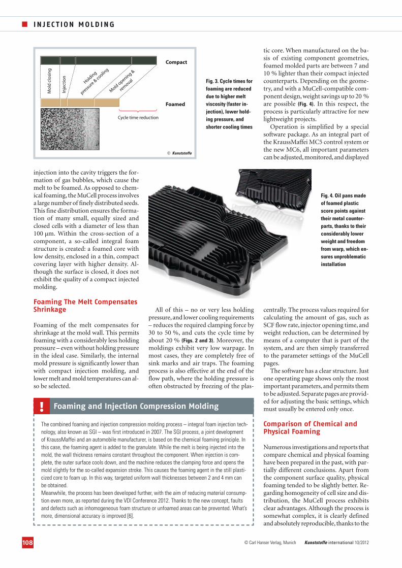
tic core. When manufactured on the ba-sis of existing component geometries,foamed molded parts are between 7 and10 % lighter than their compact injectedcounterparts. Depending on the geome-try, and with a MuCell-compatible com-ponent design, weight savings up to 20 %are possible (Fig. 4). In this respect, theprocess is particularly attractive for newlightweight projects.
Operation is simplified by a specialsoftware package. As an integral part ofthe KraussMaffei MC5 control system orthe new MC6, all important parameterscan be adjusted,monitored,and displayed
centrally. The process values required forcalculating the amount of gas, such asSCF flow rate, injector opening time, andweight reduction, can be determined bymeans of a computer that is part of thesystem, and are then simply transferredto the parameter settings of the MuCellpages.
The software has a clear structure. Justone operating page shows only the mostimportant parameters, and permits themto be adjusted. Separate pages are provid-ed for adjusting the basic settings, whichmust usually be entered only once.
Comparison of Chemical andPhysical Foaming
Numerous investigations and reports thatcompare chemical and physical foaminghave been prepared in the past, with par-tially different conclusions. Apart fromthe component surface quality, physicalfoaming tended to be slightly better. Re-garding homogeneity of cell size and dis-tribution, the MuCell process exhibitsclear advantages. Although the process issomewhat complex, it is clearly definedand absolutely reproducible, thanks to the
Mo
ld c
losi
ng
Inje
ctio
n
Holding
pressu
re &
cooling
Mold opening &
rem
oval
Cycle time reduction
Compact
Foamed
Fig. 4. Oil pans madeof foamed plasticscore points againsttheir metal counter-parts, thanks to theirconsiderably lowerweight and freedomfrom warp, which en-sures unproblematicinstallation
Fig. 3. Cycle times forfoaming are reduceddue to higher meltviscosity (faster in-jection), lower hold-ing pressure, andshorter cooling times
© Kunststoffe
The combined foaming and injection compression molding process – integral foam injection tech-nology, also known as SGI – was first introduced in 2007. The SGI process, a joint developmentof KraussMaffei and an automobile manufacturer, is based on the chemical foaming principle. Inthis case, the foaming agent is added to the granulate. While the melt is being injected into themold, the wall thickness remains constant throughout the component. When injection is com-plete, the outer surface cools down, and the machine reduces the clamping force and opens themold slightly for the so-called expansion stroke. This causes the foaming agent in the still plasti-cized core to foam up. In this way, targeted uniform wall thicknesses between 2 and 4 mm canbe obtained.Meanwhile, the process has been developed further, with the aim of reducing material consump-tion even more, as reported during the VDI Conference 2012. Thanks to the new concept, faultsand defects such as inhomogeneous foam structure or unfoamed areas can be prevented. What’smore, dimensional accuracy is improved [6].
Foaming and Injection Compression Molding!
106-110_PE111163_PE10 02.10.2012 14:39 Uhr Seite 108

109
I N J E C T I ON MOLD ING
>
Kunststoffe international 10/2012 www.kunststoffe-international.com
direct gas injection. Foaming agent coststhat are at least 80 % lower, are a furtheradvantage.
On the other hand, chemical foam-ing is very simple, due to the indirectintroduction of the foaming agent via ametering unit. However, the processcannot be influenced directly – only in-directly via temperature control andscrew speed.
One disadvantage of MuCell plastica-tion is the shortened plasticating zonecaused by the middle non-return valve,which can have an effect the required shotweight, and depends on the material used.However, regarding the choice of materi-al, the process is extremely flexible. Nitro-gen is used as foaming agent in about90 % of all applications. Therefore, theprocess is ideally suited for applicationsin which subsequent solvent evaporation(fogging) is undesirable.
Investment Costs Pay Off
On the financial side, the situation isquite clear: Although the MuCell equip-ment involves higher investment cost,the operating costs are significantly low-er (Table 1). The possible savings due toreduced foaming agent costs and lowermaterial consumption lead to an averageROI of six months up to one year (es-tablished on a machine with 6,500 kNclamping force). Obviously, the amountof material saved also depends on thesize of the molded component. As a ruleof thumb, one can assume savings rang-ing from about 10 % up to almost 20 %.
Furthermore, a significantly higher pro-ductivity must be taken into account,which is due to the shorter cycle times ofup to 20 %.
Like most other special processes,physical foaming pays off especiallywith large production quantities orhigh machine utilization. One argu-ment in favor of the latter is the slight-ly limited application flexibility of theplasticizing unit. Although the specialequipment also permits compact mold-ed parts to be produced, the shorter
plasticizing zone must be kept in mind.Therefore, in case of a correspondingdemand, it is advisable to replace theMuCell with a standard plasticizingunit.
Ongoing Projects
Obviously, the savings in material andthe associated weight reductions that areachievable with foam injection moldinghave a particularly great impact withvery large components. In order to sup-port potential as well as existing activeusers, the plastics processing companiesMürdter, Trexel, and KraussMaffeiagreed to cooperate. As a result, theworld’s largest injection molding ma-chine for the MuCell process, an MC5400-17.200 with 54,000 kN clampingforce, was commissioned in the MürdterTechnikum in Mutlangen, Germany, atthe end of 2011 (Fig. 5). With this ma-chine, a direct comparison of large com-pact injected and foamed components ispossible for the first time. Moreover, thefindings gained during the tests can beimplemented directly in the adjacentmoldmaking workshop, which savestime and money. The new machine alsopermits tests with the SGI process (inte-gral foam injection) to be carried out(see box). Proper Group, a processor inthe United States has a similar but small-er plant.
For two years already, Kunststofftech-nik Wiesmayer GmbH in Neustadt on the
... and the company offers to prototype “real” large components in the USA too. Proper Mold oper-ates an MX 2700 with MuCell equipment, which, in terms of dimensions, is less impressive, though,than the plant at the Mürtder facility (top)
Fig. 5. Jürgen Wabersich (Mürdter) (right), Andreas Handschke (KraussMaffei) (center) and Dr. Hartmut Traut (Trexel) (left) examine the world’s largest MuCell injection molding machine. TheMC 5400-17.200 with 54,000 kN clamping force, is equally suitable for compact injection molding aswell as the MuCell and SGI processes (see box)…
106-110_PE111163_PE10 02.10.2012 14:39 Uhr Seite 109

110
I N J EC T I ON MOLD ING
© Carl Hanser Verlag, Munich Kunststoffe international 10/2012
Danube, Germany, has been using theMuCell process on a large injection mold-ing machine with 16,000 kN clampingforce (type MX made by KraussMaffei).Using tandem technology on this ma-chine, Wiesmayer produces interior sup-ports for doors of the Mercedes ‘E’ class.Because the process requires no holdingpressure, the parts exhibit far lowerwarpage than compact injected compo-nents. Because the tandem technologypermits one part to be de-molded duringthe cooling phase of the other part, pro-ductivity has been boosted by a factor of1,6 [5].
Nonetheless, KraussMaffei has contin-ued its research in the chemical foamingprocess, which is being marketed togeth-er with the physical process under thename “CellForm”.
Outlook
Current developments are aimed at im-proving the surface quality of foamedcomponents. Automakers in particularare hoping for advances to be made here.Raw material suppliers are already devel-
oping suitable new materials.Alternative-ly, grained or eroded surfaces could beconsidered as a first step. For perfect, pos-sibly high-gloss visible surfaces, a combi-nation with dynamic mold temperingcould prove to be suitable, for examplewith pulse cooling, as presented byKraussMaffei at the Fakuma 2012.
Moreover, combined processes such asfoil back injection or in-mold surface dec-
oration are conceivable. Advantageoushereby are the low pressures of the Mu-Cell process. For the production of mul-ti-functional components,physical foam-ing can also be combined with the mul-ti-component technology (Fig. 6).
For the production of structural com-ponents, sandwich structures using or-ganic sheets are a possible solution. Basi-cally, however, a bright future can be pre-dicted for the MuCell process – not onlybecause of its technical advantages, butmainly because of the resource-savingmaterial consumption.�
REFERENCES
1 Altstädt, V.; Mantey, A.: Thermoplast-Schaum-spritzgießen. Carl-Hanser Verlag, München 2010
2 Bürkle, E.: Verfahren und Trends beimSpritzgießen. Kunststoffe 90 (2000) 1, S. 40-45
3 Bürkle, E.; Mitzler, J.: Spritzgießverfahren gestern,heute und morgen. Kunststoffe 95 (2005) 5, S. 51-56
4 Goldsberry, C.: Trexel pushes MuCell into themainstream.www.plasticstoday.com/articles/trexel-pushes-mucell-mainstream-0106201204
5 Betsche, M.: Immer offen für neue Technologien.Kundenmagazin „Made by KraussMaffei“, Aus-gabe 1/2010, S. 16
6 Reisch, T.; Pflamm-Jonas, T.; Radlewitz, T.;Steiger, R.: Cockpitkonzept der Zukunft amBeispiel der BMW 1-er und 3-er Reihe. In:Tagungshandbuch „Kunststoffe im Automobilbau“,VDI Verlag, Düsseldorf 2012, S. 71-81
THE AUTHORS
ANDREAS HANDSCHKE, born 1968, is technologymanager for MuCell and multi-component technologyat KraussMaffei Technologies GmbH, Munich, Ger-many
DIPL.-ING. (FH) JOCHEN MITZLER, born 1973, ishead of Strategic Product Management at Krauss-Maffei Technologies GmbH, Munich.
Process Standard MuCell
Machine CX 650 - 4300 CX 650 - 4300
Additional investment for MuCell equipment % 35
Number of cavities 1 1
Shot weight kg 1 0.85
Weight savings % 15
Cycle time s 45 38
Cycle time optimization % 18
Material price, PA as example EUR/kg 2.80 2.80
Material cost per parts EUR/part 2.80 2.38
Material cost savings EUR/part 0.42
Proportion of foaming agent % 0 0.5
Foaming agent costs (nitrogen) EUR/kg 0.3
Foaming agent costs per part EUR/part 0.001275
Annual production hours h 6,000 6,000
Number of parts per year 480,000 568,421
Foaming agent costs per year EUR 724.73
Material cost savings per year EUR 238,736.84
Total annual savings EUR 238,012.11
Table 1. Comparison of costs between compact injection molding and MuCell process: Dependingon the application, simply the material savings and higher productivity result in a return on invest-ment (ROI) between six months and one year for the additional MuCell foaming equipment
Fig. 6. Combinedprocesses using
foaming and multi-component technolo-gy are gaining in im-
portance – the exam-ple shows a cover inthe engine compart-
ment with anhard/soft foamed
combination for im-proved dimensional
stability
106-110_PE111163_PE10 02.10.2012 14:39 Uhr Seite 110