105742885 Calculation of Pressure Traverse Using Beggs and Brill
29
Calculation of Pressure Drop for a hilly terrain pipeline using Beggs & Brill correlation By Oba Fred Ajubolaka G2011/MENG/PNG/FT/846 Abiodun Benjamin Odunayo G2010/MENG/PNG/FT/804 MULTIPHASE FLOW IN PIPES DEPARTMENT OF PETROLEUM & GAS ENGINEERING UNIVERSITY OF PORT HARCOURT AUGUST, 2012 &
-
Upload
vissusamurai -
Category
Documents
-
view
107 -
download
8
description
ca
Transcript of 105742885 Calculation of Pressure Traverse Using Beggs and Brill

Calculation of Pressure Drop for a hilly terrain pipeline using Beggs &
Brill correlation
By
Oba Fred Ajubolaka
G2011/MENG/PNG/FT/846
Abiodun Benjamin Odunayo
G2010/MENG/PNG/FT/804
MULTIPHASE FLOW IN PIPES
DEPARTMENT OF PETROLEUM & GAS ENGINEERING UNIVERSITY OF PORT HARCOURT
AUGUST, 2012
&

Project Data:
D/STBq 7140
0
D/mmcf.qg 725
700.g API. 408300
.ind 12
RFT.,Ave 55090
psiaP 425
Divide Pipeline into two sections Section 1: Rises 300ft., in one mile(5280 ft.) Section 2: Drops 300ft., in 3000ft.,

Solution
Section 1
1.0 Estimate Average Pressure,
let,
2.0 Determine fluid properties from relevant
correlation at 410psia and 90°F
Determine from:
psiP 30
P
2
PPP
psia/ 410230425
sR
20481
000910
01250
10
10
18
.
t.
API.
gsP
R
Where, t=90°F , °API = 40, P =410 psia

.STB/scf.).(.Rs 70961468138700
21
25100012097590
.
t.sRo
o
g..B
Where, Rs =96.70scf/STB, t= 90°F
Bo =1.0457Bbl/STB
Determine Bo from the correlation below:

Z-Factor determination
using standing & katz correlation
gg ..pcP 537015667
gg .pcT 512325168
psia.pcP 75503
R.pcT 28394
pcP
Ppr
P 810
75503
410.
.
pcT
Tpr
T 401
28394
550.
.
But, z = ƒ(Ppr, Tpr) = 0.93

Determination of oil viscosity, µo
(d) Using the following correlations:
cp.
R.b
R.
t
x
o
o
g
od
.s
bod
.s
.
..
x
573
150445
10071510
10
110
3380
5150
1631
0202303243
Where, t = 90°F, Rs =96.70scf/stb and 700.g

Determine gas viscosity,µg
(e) First we determine ρg
Using Lee et al Correlation
3521550930
4107007272
ft/Ibm..
..
zT
. Pg
g
cp.g
g
g
.g
.g
Kg
.X..Y
.M.T
.X
.TM
TM..K
molIbm/Ibm.Mg
Y
.
gX
Exp
011550
51
9728
10
3012042
505010986
53
5311019209
02049
2820
4624

Determine surface tension σo and Bg
(f) From the plot of Baker and Swerdloff at 40°API
Correction factor of 70% , σo will be:
Bg is determined from z-factor, average pressure and
temperature:
cm/dynesod
28
cm/dynes.%dyneso 19700287028
scf/ft...
p
zT.Bg
303530410
5509300283002830

3.0 Determine flowrates & Densities
(g) Gas density,
(h) Oil density,
(i) Oil flowrate,
(j) Gas flowrate,
3521550930
4107007272
ft/Ibm..
..
zT
. Pgg
336506155
0760350ft/Ibm,
B.
R.
o
gsoo
s/ft..Bq
q ooo
34852086400
6155
s/ft.
Bqq
qgRsog
g
32181086400

4.0 Determine superficial velocities
s/ft.
.
d
q
A
qV o
p
osl 6180
1
4852044
22
s/ft.
.
d
q
A
qV
g
p
gsg 00913
1
2181044
22
Superficial velocity of liquid:
Superficial velocity of gas:
s/ft...VVV sgslm 62713009136180
Mixture velocity:

5.0 Determine flow pattern
No slip liquid holdup,
Froude Number,
Liquid Velocity Number,
Modified Flow pattern equations:
0454062713
6180.
.
.
V
V
m
sll
775
117432
62713 22.
.
.
gd
VN m
Fr
5215161619
3650618093819381
250250
...
...V.N
..
o
osllv
2012404540316316 302030201
..L ..l
873864
45213
4682
1059550
918100
91100092502
..L
..L
..L
.l
.l
.l

Flow Pattern
Since, ,
Flow pattern is Transition: transition pattern is between
segregated and intermittent flow pattern
010.l 32 LNLFr

6.0 Determine HL for Segregated &
Intermittent flow patterns
Segregated Pattern Calculation:
1880
575
045409800
08680
484600 .
.
..
N
aH
.
.bl
FrL
300ft
5280ft 3000ft ϴ1
ϴ2
7153000
300
2535280
300
12
11
.tan
.tan
Fig. 1.1 Schematic of the Pipeline as it rises and drops

Segregated HL Determination (contd)
01 LL
HH
2935056111880
5611
5235
0110
01
8133308101
01
13
1
...HH
.
.c
.e
NNeln.C
.sin..sinc.
LsegL
hFr
glv
fll
76803.f 53903.g 61401.h

Determine HL for Intermittent flow
patterns
159001241115670
01241
12160
9602
01
15670
775
045408450
01
01
0 01730
53510
....HH
.
.c
.e
NNeln.C
HH
.
.
..
N
aH
LerintL
LermittentintL
L
hFr
gLv
fLL
l
.
.
cFr
bL
l
30500.f 44730.g 09780.h

HL for Transitional flow pattern
Determine, A from:
21930
1590448612935044860
1
44860
911918
775918
1
1
111
23
3
.H
....H
HAAHH
.A
..
..
NN
NNA
transL
transL
.IntL.segLtransL
Fr

7.0 Determine Actual & Non slip denties
.ft/Ibm.
....
.ft/Ibm.
....
HH
ns
ns
LgLLns
s
s
LgLLs
3
3
743
045401521045403650
1
2312
219301521219303650
1

8.0 Determine the friction factor, ƒtp.
Determine Nre., µn, and ƒn:
)chartmoody(.Nff
)assumption(oooo.od/e
...
N
cp.
....
dVN
d/e,
.
g
n
Ren
Re
n
n
LLLn
mnsRe
020
6
10384162713743
1488
1730
04540101155004540573
1
1488
5
1730

Determine the friction factor, ƒtp.(Contd)
Determine y, s and ƒtp:
025480
02027412741
2741
2420
01853087250182305230
9440
21930
04540
2420
42
22
1
.f
..fn.f
.eef
f
.s
yln.yln.yln..
ylns
.
.
.
H
y
tp
tp
n
tp
L
L
.s
Trans
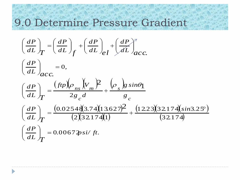
9.0 Determine Pressure Gradient
.ft/psi.dL
dP
.
.sin..
.
...
dL
dP
g
sing
dg
Vftp
dL
dP
,dL
dP
dL
dP
dL
dP
dL
dP
dL
dP
T
T
T
.acc
.accelfT
c
s
c
mns
006720
17432
253174322312
1174322
62713743025480
2
0
2
12

10.0 Determine uphill Pressure Drop, ∆P
For an horizontal distance of 0ne mile(5280ft.)
Pressure drop will be:
psi.P
.ft.ft
psi.L
dL
dPP
T4835
5280006720

Section 2 of Pipeline
Fluid properties have been determined at average
Pressure of 410psia and Temperature of 90°F. So we
continue to with these properties for downhill
calculations.
We shall proceed to determining the Liquid holdups
for
segregated and intermittent flow patterns and there
after
determine the transition holdup.
From that point we can determine the two phase
Friction factor and move on to compute the pressure
drop
for the downhill segment.

Determine Liquid Holdup for Segregated flow
pattern
12920
687401880
68740
8133308101
77061
7004
1
1880
7153000
300
2
02
0
02
23
2
12
.H
..HH
.
.sin..sinc.
.c
.e
NNelnc
.H
.tan
HH
segL
LsegL
L
LsegL
hFr
gLv
fLL
36920.f 12440.g 50560.h

Determine Liquid holdup for Intermittent flow
pattern.
We have already determined Holdup for Intermittent
flow
pattern, HL(0) = 0.1567 in the uphill segment of pipeline
and is the same for both segregated and
intermittent flow patterns in downhill. Hence,
77061.c
68740.
11730
107704486011292044860
1
107706874015670
2
2
222
2
02
.H
....H
HAAHH
...H
HH
TransL
TransL
.intLsegLTransL
.intL
L.intL

Determine actual density of fluid on downhill
3257
117301521117303650
1
ft/Ibm.
....
HH
s
s
LgLLs
Determine 2-phase friction factor
303
11730
04540
020
000060
10384
222
5
.
.
.
H
Ly
.d/e,Nffn
pipesmooth.d/e
edminerdetalready.N
.TrL
Re
Re
0320020601601
601
46990
01853087250182305230
46990
42
...f.f
.eef
f
.s
yln.yln.yln..
ylns
ntp
.s
n
tp

Determine Pressure gradient
ft/psi.ft/psf...dL
dP
.
.sin..
.
...
dL
dP
g
.sing
dg
Vf
dL
dP
dL
dP
dL
dP
dL
dP
dL
dP
T
T
cc
m
T
.accelfT
snstp
0026110376072103450
17432
71517432257
1174322
627137430320
715
2
2
2

Determine Pressure Drop
For an horizontal distance, L=3,000ft.
psi.P
psi.P
ft,ft
psi.P
LdL
dPP
T
837
30000026110
00030026110

Total Pressure drop for both uphill & downhill
psiP
psi..P
PPP
T
T
downhilluphillT
43
438374835
The Beggs and Brill Correlation is iterative. The calculated pressure
drop is not equal to the estimated pressure drop, hence, the calculated
pressure becomes our new estimated pressure drop and process is
repeated to achieved the condition where, estimated pressure drop
equals calculated pressure drop.