103. Matching a 3D Model to the Photos (1)
15
1 103. Matching a 3D Model to the Photos (1) This summer I was asked by some readers for making a tutorial on my photo-matching method. This method allowed me to recreate the shapes of various historical aircraft with greater precision than the classic scale plans. (For example – the Fokker D.V or SBD Dauntless). This is the first post on this subject (I decided to split this tutorial into two subsequent posts). The goal of the photo matching is to set up in your 3D environment a photo as the precise reference image (a more reliable equivalent to the scale plans). You can then use such a photo to verify, correct, and enhance the initial version of your 3D model. To begin, you need: 1. Initial 3D model. First you have to prepare an initial 3D model of the aircraft. You can do it in the classic way, using available scale plans and photos. This first approximation of the real aircraft does not have to be too detailed – prepare just the fuselage, wings and empennage. Eventually you can also add simplified landing gear (placing plain cylinders in place of its oleo struts) and the propeller blades; 2. High-resolution photo. Ideal reference photo should be detailed and free of barrel or pincushion distortions (i.e. it should depict the aircraft in a pure perspective projection). Of course, in practice such an ideal is not possible, but I will give you some hints how to identify a good candidate for the reference photo; I built my models and matched them to the photos in Blender 3D program. In this post I am using Blender 2.80 (this is the actual version). I assume that the Reader knows the basics of Blender environment, in particular its UI and the navigation in 3D scene (“3D View” window). However, sometimes in this post I will describe some details of Blender commands that are obvious to its regular users. In this way I just want to minimize the risk that eventual Reader will “get stuck” in the middle of the described process. For this tutorial I decided to use my old P-40 model, shown below. I built it several years ago in a “classic” way: using the scale plans. In this old model I did not used any information from the P-40 blueprints, which I presented in my blog in 2019. Figure 103-1 An initial model of the P-40 Wing shape is the only element of this model based on the explicit dimensions from original blueprint All other assemblies are not confirmed by the explicit dimensions
Transcript of 103. Matching a 3D Model to the Photos (1)

1
103. Matching a 3D Model to the Photos (1)
This summer I was asked by some readers for making a tutorial on my photo-matching method. This
method allowed me to recreate the shapes of various historical aircraft with greater precision than
the classic scale plans. (For example – the Fokker D.V or SBD Dauntless). This is the first post on this
subject (I decided to split this tutorial into two subsequent posts).
The goal of the photo matching is to set up in your 3D environment a photo as the precise reference
image (a more reliable equivalent to the scale plans). You can then use such a photo to verify,
correct, and enhance the initial version of your 3D model. To begin, you need:
1. Initial 3D model. First you have to prepare an initial 3D model of the aircraft. You can do it in
the classic way, using available scale plans and photos. This first approximation of the real
aircraft does not have to be too detailed – prepare just the fuselage, wings and empennage.
Eventually you can also add simplified landing gear (placing plain cylinders in place of its oleo
struts) and the propeller blades;
2. High-resolution photo. Ideal reference photo should be detailed and free of barrel or
pincushion distortions (i.e. it should depict the aircraft in a pure perspective projection). Of
course, in practice such an ideal is not possible, but I will give you some hints how to identify
a good candidate for the reference photo;
I built my models and matched them to the photos in Blender 3D program. In this post I am using
Blender 2.80 (this is the actual version). I assume that the Reader knows the basics of Blender
environment, in particular its UI and the navigation in 3D scene (“3D View” window). However,
sometimes in this post I will describe some details of Blender commands that are obvious to its
regular users. In this way I just want to minimize the risk that eventual Reader will “get stuck” in the
middle of the described process.
For this tutorial I decided to use my old P-40 model, shown below. I built it several years ago in a
“classic” way: using the scale plans.
In this old model I did not used any information from the P-40 blueprints, which I presented in
my blog in 2019.
Figure 103-1 An initial model of the P-40
Wing shape is the only element of this model based on the explicit dimensions from original blueprint
All other assemblies are not confirmed by the explicit dimensions

2
Here is the link to this P-40 model. It was based on the documentation that was widely available in
the previous decade. I used here some scale drawings, corrected by available photos and a few low-
resolution scans of the original blueprints published by p40warhawk.com. (For comparing these P-40
scale plans with the photos, I used methods described in this post).
In fact, this model is still too detailed for such a comparison, because I already finished it in 2013.
(Eventual adjustments of its shape will require changes in accompanying details. For example: fixing
the windscreen shape would require updates in the cockpit interior). To get a better idea how the 3D
aircraft for such a photo matching usually looks like, see the pictures of my SBD Dauntless, published
in this and this posts. In particular, keep the matched model ready for eventual changes. Form its
parts using simple meshes, smoothed by the Subdivision Surface modifiers. Create all openings
(cockpit, tail wheel, etc.) in a “dynamic” way, using Boolean modifiers with auxiliary “cutting”
objects.
Your model must contain some elements which sizes and proportions are confirmed by explicit
dimensions from the original manufacturer drawings. You will fit these “confirmed” shapes to their
counterparts in the reference photo, finding in this way the proper camera projection. Remember
also that the aircraft wingspan or the overall fuselage length are poor candidates for such tests,
especially if you found these dimensions in a printed table instead of an original blueprint. (The
printed sources are often misleading, simply repeating the errors that occurred in the earlier
materials!) It would be better to know other dimensions: for example, the distance from the firewall
to the rudder hinge, or similar. You can often find them in the general arrangement diagrams (as I did
in the case of the SBD model). In this P-40B, there is one such a confirmed element, and another,
“partially confirmed”:
• Wings – I used here a scan of the original blueprint published by p40warhawk.com. (Despite
of the poor quality of this image, the wing dimensions are still readable). From other
technical descriptions I learned that the wing airfoils were NACA-2215 at the root and NACA-
2209 at the tip, incidence angle: 1⁰, wing dihedral: 6⁰. This data describes quite precisely the
wing shape;
• Empennage – I used here scans of the fin, rudder, and elevator blueprints, from the same
portal. However, the dimensions in these images were not readable. I was able just to couple
the fin and elevator along their hinge lines and fit them into the general P-40 side view.
Because these images lacked dimensions, I could make some minor errors in their scale,
location or orientation in relation to the fuselage. There were no similar drawings of the
horizontal stabilizer, thus the shape of this part is just my assumption, based on the available
photos;
Unfortunately, the available P-40 general arrangement diagrams contain just a few key dimensions.
They did not allow me to determine the wing position in relation to the firewall, or the distance from
the firewall to the fin/rudder. (I will not even mention the lack of the fuselage stations locations,
which were very helpful in the case of my SBD model).
How to find a good reference photo? If you are lucky and there are some survived/restored aircraft
of the type you are modeling, you can review their photos. The best case is a detailed, high
resolution picture made with telephoto (i.e. very long) lens. Usually this means a photo of the flying
aircraft. In such an image the barrel distortion can be neglected. In this first part of the tutorial I will
use such a photo, made during an air show in Duxford:
3
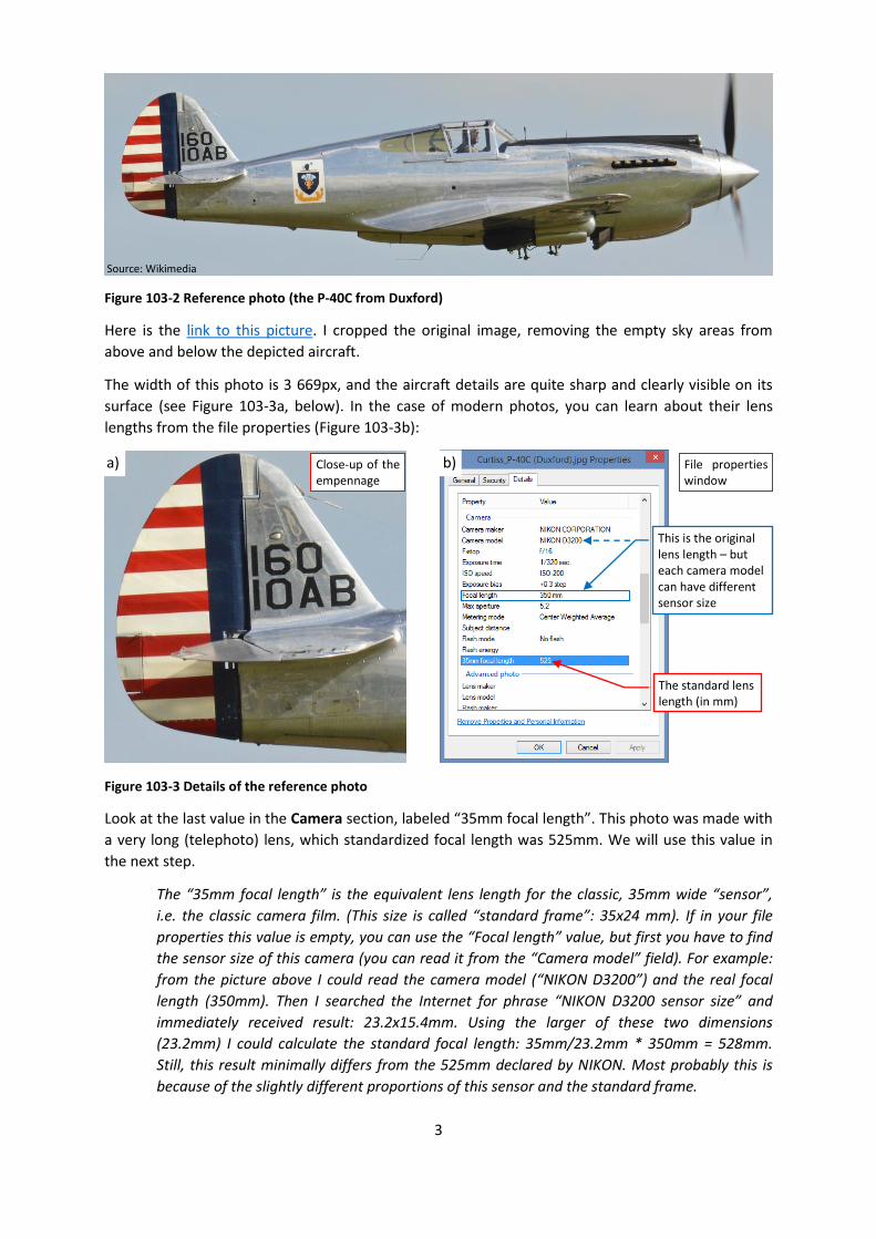
Figure 103-2 Reference photo (the P-40C from Duxford)
Here is the link to this picture. I cropped the original image, removing the empty sky areas from
above and below the depicted aircraft.
The width of this photo is 3 669px, and the aircraft details are quite sharp and clearly visible on its
surface (see Figure 103-3a, below). In the case of modern photos, you can learn about their lens
lengths from the file properties (Figure 103-3b):
Figure 103-3 Details of the reference photo
Look at the last value in the Camera section, labeled “35mm focal length”. This photo was made with
a very long (telephoto) lens, which standardized focal length was 525mm. We will use this value in
the next step.
The “35mm focal length” is the equivalent lens length for the classic, 35mm wide “sensor”,
i.e. the classic camera film. (This size is called “standard frame”: 35x24 mm). If in your file
properties this value is empty, you can use the “Focal length” value, but first you have to find
the sensor size of this camera (you can read it from the “Camera model” field). For example:
from the picture above I could read the camera model (“NIKON D3200”) and the real focal
length (350mm). Then I searched the Internet for phrase “NIKON D3200 sensor size” and
immediately received result: 23.2x15.4mm. Using the larger of these two dimensions
(23.2mm) I could calculate the standard focal length: 35mm/23.2mm * 350mm = 528mm.
Still, this result minimally differs from the 525mm declared by NIKON. Most probably this is
because of the slightly different proportions of this sensor and the standard frame.
Source: Wikimedia
The standard lens length (in mm)
This is the original lens length – but each camera model can have different sensor size
a) b) Close-up of the empennage
File properties window
4
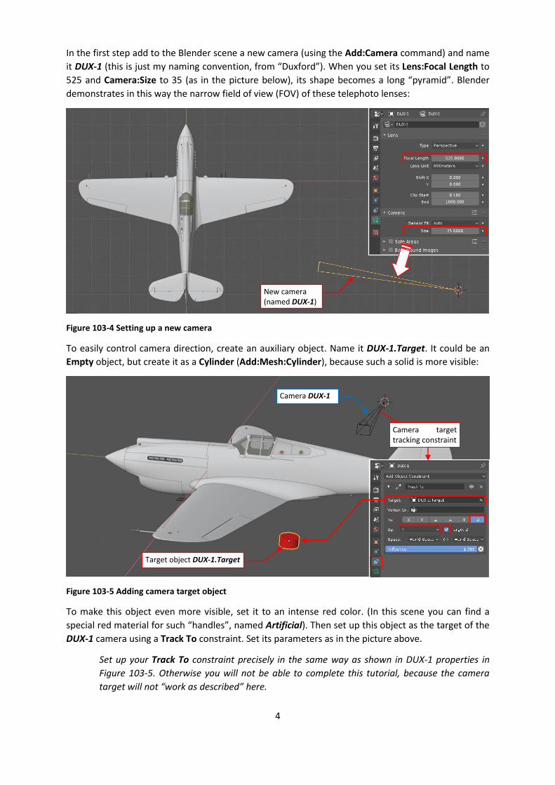
In the first step add to the Blender scene a new camera (using the Add:Camera command) and name
it DUX-1 (this is just my naming convention, from “Duxford”). When you set its Lens:Focal Length to
525 and Camera:Size to 35 (as in the picture below), its shape becomes a long “pyramid”. Blender
demonstrates in this way the narrow field of view (FOV) of these telephoto lenses:
Figure 103-4 Setting up a new camera
To easily control camera direction, create an auxiliary object. Name it DUX-1.Target. It could be an
Empty object, but create it as a Cylinder (Add:Mesh:Cylinder), because such a solid is more visible:
Figure 103-5 Adding camera target object
To make this object even more visible, set it to an intense red color. (In this scene you can find a
special red material for such “handles”, named Artificial). Then set up this object as the target of the
DUX-1 camera using a Track To constraint. Set its parameters as in the picture above.
Set up your Track To constraint precisely in the same way as shown in DUX-1 properties in
Figure 103-5. Otherwise you will not be able to complete this tutorial, because the camera
target will not “work as described” here.
New camera (named DUX-1)
Camera DUX-1
Target object DUX-1.Target
Camera target tracking constraint

5
Then select DUX-1 and set it as the active camera (View:Cameras:Set Active Object as Camera).
When you did this, switch one of the 3D Views to the “Camera” view (typing [0] or
View:Viewpoint:Camera). In this view you will see a picture similar to Figure 103-6:
Figure 103-6 Initial view from the DUX-1 camera
In the center of the camera frame you can see the target object. (To “see through” the aircraft
fuselage, turn on the “X-ray” option for this window). However, this camera has a narrow field of
view, and is too close to this model, so you can see just a fragment of the fuselage in its frame.
To move this camera away from this model, do following in another 3D View window:
1. Choose the Transform tool;
2. Switch the current transform orientation to Local direction;
3. Select the camera DUX-1 object;
4. Start dragging its blue (local Z) axis away from the model:
Figure 103-7 Dragging the camera away from the model
To see the target object, turn on the “X-ray” view option
Object DUX-1.Target – always in the center
Camera DUX-1
Camera View Top View
1. 2.
3.
4. Drag this axis

6
You can also quickly invoke this command by selecting the camera frame in the camera view,
activating (moving the mouse cursor to) the Top view, and typing there [G], [Z] keyboard
shortcuts. (This way is especially useful when you cannot see the camera object in the top
view. It often happens for such long-lens cameras as this one).
As you move mouse, the camera moves away, and in its frame you can see more of the model:
Figure 103-8 Dragging the camera away from the model (cont.)
However, suddenly your model can start disappearing behind something that looks like an invisible
wall:
Figure 103-9 Camera clipping effect
To fix this effect, change the Camera:Lens settings shown in the picture above. Increase the Clip End
value (it should be greater than the final distance from the model to the camera). To be on the “safe
side” I suggest increasing the Clip End value of DUX-1 camera to 3000 units. Simultaneously, to
remove the ugly “protrusions” of the inner model surfaces, increase the Clip Start parameter to a
higher value – for example 3. (For this static camera, you can safely increase this value even to 30).
Continue moving the mouse (camera object is now out of this viewport bounds)
Current distance from the starting point In camera view you can
see more of the model
This “invisible wall” is here
To avoid these “protrusions”, increase this value
7
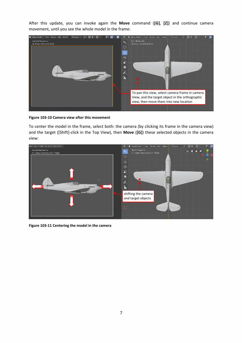
After this update, you can invoke again the Move command ([G], [Z]) and continue camera
movement, until you see the whole model in the frame:
Figure 103-10 Camera view after this movement
To center the model in the frame, select both: the camera (by clicking its frame in the camera view)
and the target ([Shift]-click in the Top View), then Move ([G]) these selected objects in the camera
view:
Figure 103-11 Centering the model in the camera
To pan this view, select camera frame in camera View, and the target object in the orthographic view, then move them into new location
shifting the camera and target objects

8
If you want to rotate the model in the camera frame, select the target object only and rotate it
(Object:Transform:Rotate, or the [R] shortcut key) in the camera view:
Figure 103-12 Rotating the model in the frame
Before this operation make sure that your Pivot Point mode (visible in the 3D View window
header) is not set to “3D Cursor”. It can be an of these: “Bounding Box”, “Active Object”,
“Individual Origins”.
Note that the target object in the camera frame seems to not rotate. This is because the camera
follows its rotation.
In the next step adjust the camera frame aspect ratio. To do this, open the Properties window,
Output section, Dimensions panel, and type the reference image width and height in the Resolution
X and Resolution Y fields (as in the picture below):
Figure 103-13 Adjusting camera frame aspect ratio
Select camera target object
Rotate it in the Camera View
Dimensions (in pixels) of the reference photo
Correct aspect ratio
Pivot point mode: Active Object
Properties window

9
Then in the DUX-1 camera properties assign the reference image as the background image:
Figure 103-14 Assigning reference image to the camera
(The Open button opens a file selection window. Pick there your image file). After loading, set
following image parameters in the Background Images panel: Depth to “Front”, and Frame Method
to “Crop” (as below):
Figure 103-15 Adjusting background image settings
You can also adjust the Alpha (image transparency) value, to better see the model behind this photo.
Click this button to open initial subpanel
Click this button to load the image
Alpha value controls image transparency

10
For further camera adjustments, arrange three 3D View panes on your Blender screen:
Figure 103-16 Suggested “workbench”
Place the camera view on the top. You will observe there the results of your camera/target
movements. The goal is to set up a projection, in which the model (or, at least, the confirmed
fragments of the model) will fit the photo. Place below two orthographic views, where you will
perform all the object transformations (Move, Rotate). Usually you will apply them to the target
object, but sometimes you will also move the camera.
Note that the current Transformation orientation is still set to “Local” (see this setting in the
3D View header in the picture above). In this tutorial I assumed that you have also set it up in
this way in your Blender scene.
For the beginning you have to close the camera to the target, because at this moment the model
seems to be smaller than in the photo. Of course, you can do it using the visual gadgets, as you did in
Figure 103-7. However, to invoke this transformation quickly you can also use following shortcuts:
1. select the camera object (DUX-1) by clicking its frame in the camera view;
2. move mouse cursor over one of the orthogonal views, and type there: [G], then [Z] ([G] key
invokes the Move command, [Z] key restricts its trajectory to the camera Z axis);
The active window in Blender is the window under your mouse cursor – that’s why in p. 2. I
mentioned the mouse position. I will skip this detail in further command descriptions, writing
simply “in the orthographic view, type …”.
Camera View
Orthographic views
Camera target

11
Being in the Move mode, shift your mouse to bring the camera closer to the model. Confirm this
operation when you see in the camera view that the size of the model matches the photo:
Figure 103-17 Closing the camera, to fit the model relative size to the reference photo
However, you still have to pan (as in Figure 103-11) and rotate (as in Figure 103-12) this model to fit
it to the original silhouette from the photo. After several “rounds” of such adjustments (altering the
camera-target distance, panning the camera frame, rotating the target in the camera view) you can
reach following result:
Figure 103-18 The initial match
Now you can assess the differences between the photo and the model orientation. In this case you
can do it using the confirmed element of your model: the wing. Comparing its shape with the photo
(as above) you can see that you have to increase camera elevation, then slightly rotate the camera to
the rear.
You could do it by shifting the camera upward and rearward. However, it would also alter the model
position within the camera frame. A more effective way is to rotate the camera and its target along a
3D Cursor. (In this case the point, where you will place the 3D Cursor, will remain fixed in the camera
frame).
Move the camera closer
We still have to adjust the model (i.e. camera) orientation
12
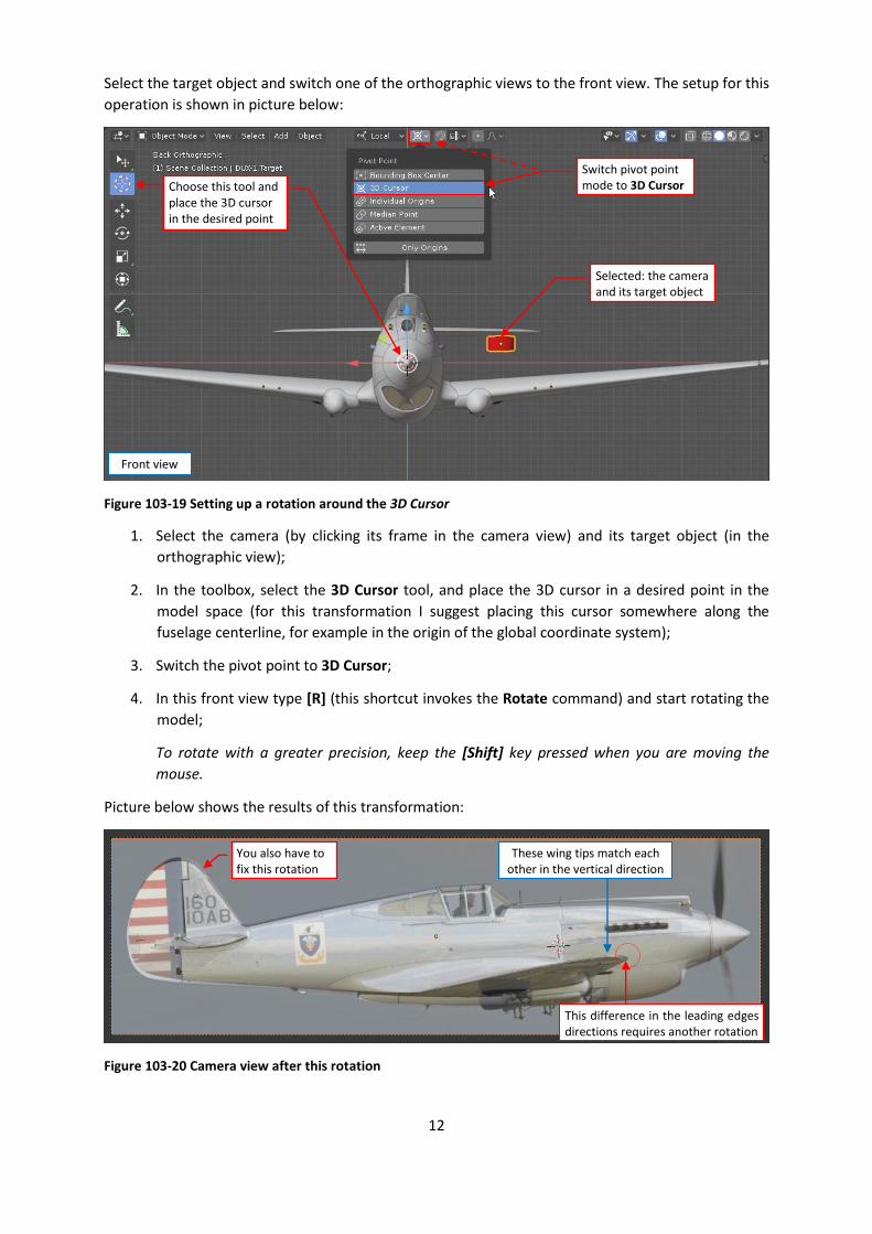
Select the target object and switch one of the orthographic views to the front view. The setup for this
operation is shown in picture below:
Figure 103-19 Setting up a rotation around the 3D Cursor
1. Select the camera (by clicking its frame in the camera view) and its target object (in the
orthographic view);
2. In the toolbox, select the 3D Cursor tool, and place the 3D cursor in a desired point in the
model space (for this transformation I suggest placing this cursor somewhere along the
fuselage centerline, for example in the origin of the global coordinate system);
3. Switch the pivot point to 3D Cursor;
4. In this front view type [R] (this shortcut invokes the Rotate command) and start rotating the
model;
To rotate with a greater precision, keep the [Shift] key pressed when you are moving the
mouse.
Picture below shows the results of this transformation:
Figure 103-20 Camera view after this rotation
Selected: the camera and its target object
Switch pivot point mode to 3D Cursor Choose this tool and
place the 3D cursor in the desired point
Front view
These wing tips match each other in the vertical direction
This difference in the leading edges directions requires another rotation
You also have to fix this rotation

13
We matched the wing vertical position, but to match the wing leading edges, you still have to rotate
the camera and its target in the top view (around the same pivot point).
In the next step you will also have to rotate the target object alone (as in Figure 103-12) to shift the
tailplane upward and the spinner tip downward.
Probably you will need several “rounds” of similar adjustments to finally fit the wing (i.e. the only
confirmed element of this model) to reference photo. It seems that the other parts of this model
match their counterparts in the camera view image. Now you can identify the differences between
my model and the original P-40C:
Figure 103-21 Matched P-40 model and the identified differences
Looking at this match I quickly found first 11 variations:
1. The fin and rudder are too low. (As I wrote earlier, the dimensions on their blueprints were
unreadable. When in 2009 I fitted scans of this assembly to the general drawing of the side
view I probably assumed a wrong scale). I expected to use them as a confirmed element, but
it occurs that you should never do such a thing for the part that is not based on explicit
dimensions;
2. Fuselage upper edge on the photo is a little bit higher;
3. Windscreen lower frame in my model should be shifted back;
4. Exhaust stack opening in the engine cowling is higher than in my model. (The same applies to
the seams of the cowling panels).
5. Carburetor air scoop on the photo is little bit lower (I remember that I remodeled it several
times in 2011, looking at the reference photos. Ultimately I enlarged it a little bit. As you can
see, such an “eyeballing” leads to errors);
6. Spinner should be a little bit shorter (this is the same “eyeballing” error as in p. 5);
7. Air intake below the spinner was closer to the firewall (by about an inch) – the same reason
as in p. 5 and 6. (If you are just looking at the same reference photos too long, you are
starting to see wrong things!).
8. Cowling flaps were closer to the firewall (as the air intake from p. 7);
9. Wrong shape of the landing gear nacelles;
10. The vent (?) on the bottom fuselage was closer to the tail;
11. The rudder in my model is “hinged” too low (the same reason as in p. 1 – lack of the explicit
dimensions);
1.
3.
7.
5.
8. 10.
6.
9. 11.
2. 4.

14
Of course, this is not the full list. When I switched Viewport Shading options of the Camera View to
Flat and the colors to Random, I was able to find even more differences:
Figure 103-22 Switching Viewport Shading to contrast colors (for easier comparison with the photo)
The first impulse is to fix all the model flaws that you have found. In principle, this is quite easy. Once
you fit your model to a photo, you can use this image like a scale plan. The perspective projection is
not any obstacle. You can edit and move the mesh vertices also in the camera view:
Figure 103-23 Using matched photo as a reference in modeling
Scale objects here just like in the orthogonal view. In case of other transformations (Move, Rotate)
restrict their space to one of the orthogonal planes (for example: type [Shift]-[Z] to restrict current
transformation to the XY plane), or to a single axis ([X], [Y], [Z]). The local coordinates of the
subsequent objects can be a great help here, if you planned them wisely. (For example: for the
stabilizer, I can use the local coordinate system aligned to the chord of its root airfoil).
However, this photo-matching method is not without its own flaws, and not all differences that you
can see in this image are the real ones. After this first result you can make a break, then review again
the wing match. I discovered that I can improve it, minimally adjusting the camera and target
position. In particular, note that the rudder of the depicted aircraft seems to be deflected to the
starboard (it is indicated by the significant deflection of its trimmer). Frankly speaking, I missed badly
any confirmed distances related to the empennage and the firewall location. Finally, I decided that
the camera was a little bit closer, so that the location of the propeller blades match the photo, as
I enabled this option, to better see model details behind the photo
Scale, rotate and move restricting the transformation to orthogonal planes (XY, ZY, ZX) or axes (X, Y, Z)

15
well as the fin. In this variant, not only the spinner but also the engine cowling is too long, but all
remaining parts of this model fit better this photo (in particular – the windshield frame):
Figure 103-24 Results of the minor adjustments in the reference camera projection
Here is the link to this matched model.
I should also consider that I used a photo of a restored aircraft. Usually the restoration teams do
their best in recreating the original aircraft, but there still can be minor variations (for example,
caused by the technological issues). For example – the aircraft from this picture is missing the front
castings in its gun cowlings. That’s why it is a good idea to match your model to several different
photos of various restored aircraft of this type, before you start altering its shape.
Of course, one of the most reliable sources are the historical photos. Unfortunately, in their case
there is additional unknown element: their focal lens length. They are also prone to various
distortions. In the next part of this tutorial I will describe how to deal with these issues.
Now the fin fits better this photo
I matched locations of the propeller blades
If I rotate this rudder by 12⁰, it fits the photo
There is a difference in the lengths of the engine cowling and spinner
Model outline


![ROAD TO mal April 2008 No. 103 mal Matching Fund ...€¦ · hm-]îznu (Venture Capital) mai (Venture Capital Fund) "Quu Venture Capital Fund mai Matching Fund 2 1 mai Matching Fund](https://static.fdocuments.us/doc/165x107/5f02b2ae7e708231d4058fdd/road-to-mal-april-2008-no-103-mal-matching-fund-hm-znu-venture-capital.jpg)