10.1' P-CAP Slim-line HMI - Primelco€¦ · 10.1" S-Series HMI User Manual iv Advisory Conventions...
100
10.1"S-Series HMI W10IB3S-PCH2AC-PoE (with LED light bar) W10IB3S-PCH2-PoE (without LED light bar) Slim-line User Manual Version 1.1 Manual Part Number: 9152111I100M
Transcript of 10.1' P-CAP Slim-line HMI - Primelco€¦ · 10.1" S-Series HMI User Manual iv Advisory Conventions...

10.1"S-Series HMI
W10IB3S-PCH2AC-PoE (with LED light bar) W10IB3S-PCH2-PoE (without LED light bar)
Slim-line
User Manual Version 1.1
Manual Part Number: 9152111I100M

10.1" S-Series HMI User Manual ii
Preface
Copyright Notice No part of this document may be reproduced, copied, translated, or transmitted
in any form or by any means, electronic or mechanical, for any purpose, without
the prior written permission of the original manufacturer.
Trademark Acknowledgement Brand and product names are trademarks or registered trademarks of their
respective owners.
Disclaimer We reserve the right to make changes, without notice, to any product, including
circuits and/or software described or contained in this manual in order to
improve design and/or performance. We assume no responsibility or liability for
the use of the described product(s) conveys no license or title under any patent,
copyright, or masks work rights to these products, and make no representations
or warranties that these products are free from patent, copyright, or mask work
right infringement, unless otherwise specified. Applications that are described in
this manual are for illustration purposes only. We make no representation or
guarantee that such application will be suitable for the specified use without
further testing or modification.

10.1" S-Series HMI User Manual iii
Warranty Our warranty guarantees that each of its products will be free from material and
workmanship defects for a period of one year from the invoice date. If the
customer discovers a defect, we will, at his/her option, repair or replace the
defective product at no charge to the customer, provide it is returned during the
warranty period of one year, with transportation charges prepaid. The returned
product must be properly packaged in its original packaging to obtain warranty
service. If the serial number and the product shipping data differ by over 30
days, the in-warranty service will be made according to the shipping date. In the
serial numbers the third and fourth two digits give the year of manufacture, and
the fifth digit means the month (e. g., with A for October, B for November and C
for December).
For example, the serial number 1W14Axxxxxxxx means October of year 2014.
Customer Service
We provide a service guide for any problem by the following steps: First, visit
the website of our distributor to find the update information about the product.
Second, contact with your distributor, sales representative, or our customer
service center for technical support if you need additional assistance.
You may need the following information ready before you call:
Product serial number
Software (OS, version, application software, etc.)
Description of complete problem
The exact wording of any error messages
In addition, free technical support is available from our engineers every business
day. We are always ready to give advice on application requirements or specific
information on the installation and operation of any of our products.

10.1" S-Series HMI User Manual iv
Advisory Conventions Four types of advisories are used throughout the user manual to provide helpful
information or to alert you to the potential for hardware damage or personal injury.
These are Notes, Important, Cautions, and Warnings. The following is an example of
each type of advisory.
NOTE: A note is used to emphasize helpful information
IMPORTANT: An important note indicates information that is important for you to know.
CAUTION/ ATTENTION A Caution alert indicates potential damage to hardware and explains how to avoid the potential problem. Une alerte d’attention indique un dommage possible à l’équipement et explique comment éviter le problème potentiel.
WARNING!/ AVERTISSEMENT! An Electrical Shock Warning indicates the potential harm from electrical hazards and how to avoid the potential problem. Un Avertissement de Choc Électrique indique le potentiel de chocs sur des emplacements électriques et comment éviter ces problèmes.
ALTERNATING CURRENT / MISE À LE TERRE! The Protective Conductor Terminal (Earth Ground) symbol indicates the potential risk of serious electrical shock due to improper grounding. Le symbole de Mise à Terre indique le risqué potential de choc électrique grave à la terre incorrecte.
10.1" S-Series HMI User Manual v
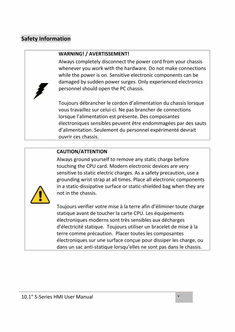
Safety Information
WARNING! / AVERTISSEMENT!
Always completely disconnect the power cord from your chassis whenever you work with the hardware. Do not make connections while the power is on. Sensitive electronic components can be damaged by sudden power surges. Only experienced electronics personnel should open the PC chassis.
Toujours débrancher le cordon d’alimentation du chassis lorsque vous travaillez sur celui-ci. Ne pas brancher de connections lorsque l’alimentation est présente. Des composantes électroniques sensibles peuvent être endommagées par des sauts d’alimentation. Seulement du personnel expérimenté devrait ouvrir ces chassis.
CAUTION/ATTENTION
Always ground yourself to remove any static charge before touching the CPU card. Modern electronic devices are very sensitive to static electric charges. As a safety precaution, use a grounding wrist strap at all times. Place all electronic components in a static-dissipative surface or static-shielded bag when they are not in the chassis. Toujours verifier votre mise à la terre afin d’éliminer toute charge statique avant de toucher la carte CPU. Les équipements électroniques moderns sont très sensibles aux décharges d’électricité statique. Toujours utiliser un bracelet de mise à la terre comme précaution. Placer toutes les composantes électroniques sur une surface conçue pour dissiper les charge, ou dans un sac anti-statique lorsqu’elles ne sont pas dans le chassis.

10.1" S-Series HMI User Manual vi
Safety Precautions For your safety carefully read all the safety instructions before using the
device. Keep this user manual for future reference.
Always disconnect this equipment from any AC outlet before cleaning.
Do not use liquid or spray detergents for cleaning. Use a damp cloth.
For pluggable equipment, the power outlet must be installed near the
equipment and must be easily accessible.
Keep this equipment away from humidity.
Put this equipment on a reliable surface during installation. Dropping it
or letting it fall could cause damage.
The openings on the enclosure are for air convection and to protect the
equipment from overheating.
CAUTION/ATTENTION
Do not cover the openings!
Ne pas couvrir les ouvertures!
Before connecting the equipment to the power outlet make sure the
voltage of the power source is correct.
Position the power cord so that people cannot step on it. Do not place
anything over the power cord.
If the equipment is not used for a long time, disconnect it from the
power source to avoid damage by transient over-voltage.
Never pour any liquid into an opening. This could cause fire or electrical
shock.
Never open the equipment. For safety reasons, only qualified service
personnel should open the equipment.
All cautions and warnings on the equipment should be noted.

10.1" S-Series HMI User Manual vii
*Let service personnel to check the equipment in case any of the
following problems appear:
o The power cord or plug is damaged.
o Liquid has penetrated into the equipment.
o The equipment has been exposed to moisture.
o The equipment does not work well or you cannot get it to work
according to the user manual.
o The equipment has been dropped and damaged.
o The equipment has obvious signs of breakage.
Do not leave this equipment in an uncontrolled environment where the
storage temperature is below -20°C (-4°F) or above 60°C (140°F). It may
damage the equipment.
CAUTION/ATTENTION
Use the recommended mounting apparatus to avoid risk of injury. Utiliser l’appareil de fixation recommandé pour éliminer le risque de blessure.
WARNING! / AVERTISSEMENT! Only use the connection cords that come with the product. When in doubt, please contact the manufacturer. Utiliser seulement les cordons d’alimentation fournis avec le produit. Si vous doutez de leur provenance, contactez le manufacturier.
WARNING!/ AVERTISSEMENT! Always ground yourself against electrostatic damage to the device. Toujours vérifier votre mise à la terre afin que l’équipement ne se décharge pas sur vous.

10.1" S-Series HMI User Manual viii
Cover workstations with approved anti-static material. Use a wrist
strap connected to a work surface and properly grounded tools and
equipment.
Use anti-static mats, heel straps, or air ionizer for added protection.
Handle electrostatic-sensitive components, PCB’s and assemblies by
the case or the edge of the board.
Avoid contact with pins, leads, or circuitry.
Turn off power and input signals before inserting and removing
connectors or test equipment.
Keep the work area free of non-conductive materials, such as ordinary
plastic assembly aids and Styrofoam.
Use filed service tools, such as cutters, screwdrivers, and vacuum
cleaners that are conductive.
Always put drivers and PCB’s component side on anti-static foam.

10.1" S-Series HMI User Manual ix
Important Information
Countries/ Area
Symbol This equipment complies with essential requirements of:
European Union
Electromagnetic Compatibility Directive(2014/30/EU) Low Voltage Directive (2014/35/EU) Restrictions of the use of certain hazardous substances (RoHS) Directive (2011/65/EU)
USA
FCC Part 15 Subpart B Regulations Class B
Federal Communications Commission Radio Frequency Interface Statement
This device complies with part 15 FCC rules.
Operation is subject to the following two conditions:
This device may not cause harmful interference.
This device must accept any interference received
including interference that may cause undesired operation.
This equipment has been tested and found to comply with the limits for a class
"B" digital device, pursuant to part 15 of the FCC rules. These limits are designed
to provide reasonable protection against harmful interference when the
equipment is operated in a commercial environment. This equipment generates,
uses, and can radiate radio frequency energy and, if not installed and used in
accordance with the instruction manual, may cause harmful interference to radio
communications. Operation of this equipment in a residential area is likely to
cause harmful interference in which case the user will be required to correct the
interference at him own expense.
Refer to Certificates for the original document.

10.1" S-Series HMI User Manual x
EC Declaration of Conformity
[English]
The object of the declaration described above [A] is in conformity with the
requirement of the following EU legislations [B] and harmonized standards [C].
Product also complies with the Council directions [D].
[German]
Das oben beschriebene Objekt [A] entspricht den Anforderungen der nachfolgend
aufgeführten EU-Vorgben [B] und den harmonisierten Normen [C]. Das Produkt
entspricht außerdem den EU-Direktiven [D].
[French]
L'objet de la déclaration décrite ci-dessus [A] est conformité aux conditions stipulées
dans les législations de l’Union européenne énoncées ci-après [B] et aux normes
harmonisées [C]. Ce produit est également conforme aux directives du Conseil
européen [D].
[Other languages]
Other languages are available upon request.
Refer to Certificates for the original document.

10.1" S-Series HMI User Manual xi
Revision History
Version Date Note Author
1.1 15-Jan-2016 Update BIOS Setup, mounting solutions, connector pinouts
Kent Ou-Yong
10.1" S-Series HMI User Manual xii
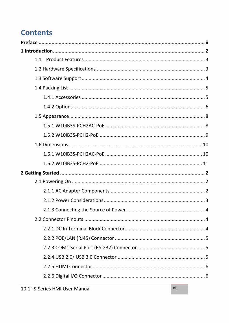
Contents Preface .................................................................................................................... ii
1 Introduction .......................................................................................................... 2
1.1 Product Features ....................................................................................... 3
1.2 Hardware Specifications .............................................................................. 3
1.3 Software Support ......................................................................................... 4
1.4 Packing List .................................................................................................. 5
1.4.1 Accessories ......................................................................................... 5
1.4.2 Options ............................................................................................... 6
1.5 Appearance .................................................................................................. 8
1.5.1 W10IB3S-PCH2AC-PoE ........................................................................ 8
1.5.2 W10IB3S-PCH2-PoE ............................................................................ 9
1.6 Dimensions ................................................................................................ 10
1.6.1 W10IB3S-PCH2AC-PoE ...................................................................... 10
1.6.2 W10IB3S-PCH2-PoE .......................................................................... 11
2 Getting Started ..................................................................................................... 2
2.1 Powering On ................................................................................................ 2
2.1.1 AC Adapter Components .................................................................... 2
2.1.2 Power Considerations ......................................................................... 3
2.1.3 Connecting the Source of Power ......................................................... 4
2.2 Connector Pinouts ....................................................................................... 4
2.2.1 DC In Terminal Block Connector.......................................................... 4
2.2.2 POE/LAN (RJ45) Connector ................................................................. 5
2.2.3 COM1 Serial Port (RS-232) Connector ................................................. 5
2.2.4 USB 2.0/ USB 3.0 Connector ............................................................... 5
2.2.5 HDMI Connector ................................................................................. 6
2.2.6 Digital I/O Connector .......................................................................... 6

10.1" S-Series HMI User Manual xiii
2.3 Turning On ................................................................................................... 6
2.4 Configuring Serial Port COM1 ...................................................................... 6
2.5 Turning Off ................................................................................................... 8
3 Operating the HMI Device ................................................................................... 10
3.1 System Settings .......................................................................................... 10
3.1.1 Hot Tab Menu ................................................................................... 10
3.1.2 Utilities ............................................................................................. 10
3.1.3 Brightness ......................................................................................... 10
3.1.4 Volume ............................................................................................. 11
3.1.5 LED Light Bar (Easy-Testing) .............................................................. 11
3.1.6 Performance ..................................................................................... 12
3.1.7 Touch Lock ........................................................................................ 12
3.1.8 HF RFID ............................................................................................. 12
3.2 Operating System ....................................................................................... 16
4 Driver Installation ............................................................................................... 18
4.1 Installing Chipset Driver ............................................................................. 18
4.2 Installing Graphics Driver ........................................................................... 21
4.3 Installing Intel Sideband Fabric Device (Intel MBI) Driver (Windows 8) ..... 22
4.4 Installing Intel Trusted Engine Interface (Intel TXE) Driver ......................... 23
4.5 Installing Intel Network Connections ......................................................... 24
4.6 Installing Audio Driver ................................................................................ 25
4.7 Installing USB 3.0 Driver (Windows 7) ........................................................ 26
5 BIOS Setup .......................................................................................................... 29
5.1 When and How to Use BIOS Setup ............................................................. 29
5.2 BIOS Functions ........................................................................................... 30
5.2.1 Main Menu ....................................................................................... 31
5.2.2 Advanced Menu ................................................................................ 32

10.1" S-Series HMI User Manual xiv
5.2.3 Chipset Menu ................................................................................... 52
5.2.4 Security Menu ................................................................................... 53
5.2.5 Boot Configuration ........................................................................... 54
5.2.6 Save & Exit ........................................................................................ 56
5.3 Using Recovery Wizard to Restore Computer ............................................ 58
6 Mounting Solutions ............................................................................................ 61
6.1 Cable Mounting Considerations ................................................................. 61
5.2 Safety Precautions ..................................................................................... 62
5.3 Mounting Guide ......................................................................................... 62
5.3.1 VESA Mount ...................................................................................... 62
5.3.2 Flush Mount / Panel Mount .............................................................. 63
5.4 Optional Mounting Solutions ..................................................................... 64
5.4.1 Front Side Wall Mount ...................................................................... 64
5.4.2 Desk Stand ........................................................................................ 65
7 Technical Support ............................................................................................... 67
7.1 Software Developer Support ...................................................................... 67
7.1.1 Digital I/O SDK .................................................................................. 67
7.1.2 Watchdog SDK .................................................................................. 67
7.1.3 LED Light Bar Porting Guide .............................................................. 67
7.1.4 RFID Porting Guide ............................................................................ 67
7.2 Problem Report Form ................................................................................ 68
8 Certificates .......................................................................................................... 70
8.1 FCC Declaration of Conformity ................................................................... 70
8.1.1 W10IB3S-PCH2AC-PoE ...................................................................... 70
8.1.2 W10IB3S-PCH2AC-POE ...................................................................... 71
8.2 EC Declaration of Conformity ..................................................................... 72
8.2.1 W10IB3S-PCH2AC-PoE ...................................................................... 72

10.1" S-Series HMI User Manual xv
8.2.2 W10IB3S-PCH2AC-POE ...................................................................... 73

10.1" S-Series HMI User Manual
1
Introduction This chapter gives you product overview, describes features and hardware specification. You will find all accessories that come with the HMI device in the packing list. Mechanical dimensions and drawings included in this chapter.

10.1" S-Series HMI User Manual
2
1 Introduction
Interactive and smart automation systems of intelligent buildings are in a
fast growing phase. Winmate multi-touch S-Series HMI is suitable for home
automation and room management systems. Flat surface is easy-to-clean
and delivers aesthetically pleasing look for any interior. The device
provides real time update for booking status and available schedule, or
performs as a synchronous display in meetings. Optional HF RFID 13.56
MHz is especially useful in access control applications.
S-Series HMI run on 1.83GHz Intel® Celeron® N2930 processor and support
Windows 10 IoT, Windows Embedded 8.1 Industry Pro, Windows
Embedded 8 Standard, Windows 7 Pro for Embedded Systems, and
Windows Embedded Standard 7 – WS7P. The HMI features P-Cap touch-
screen with 1280 x 800 pixel resolution. For easy, quick and cost effective
network installations both models support PoE. These models sealed with
front IP 65 dust and water proof, and IP22 on the back side.
The W10IB3S-PCH2AC-PoE model supports an exceptional feature - LED
light bar. With the help of red, green, blue and orange LED indicators you
can see the status of the machine or processes afar. It significantly reduces
power consumption by keeping the display turned off.

10.1" S-Series HMI User Manual
3
1.1 Product Features
Model Name
W10IB3S-PCH2AC-PoE W10IB3S-PCH2-PoE
Product Line 10.1” S-Series HMI (Slim-line)
Resolution 1280 x 800
Operating System
Windows 10 IoT Windows Embedded 8.1 Industry Pro
Windows Embedded 8 Standard Windows 7 Pro for Embedded Systems
Windows Embedded Standard 7 – WS7P
CPU Ultra-low power consumption with Intel® Celeron® N2930
processor
Cooling System Fanless cooling system
IP Rating Front: IP65 water and dust proof
Rear: IP22
LED Light Bar Default N/A
HF RFID Optional N/A
PoE Default (IEEE 802.3at)
1.2 Hardware Specifications
System:
Processor Intel ® Celeron ® Bay Trail-M N2930 1.83GHz
System Chipset Intel® ATOM SoC Integrated
System Memory 2GB DDR3L 1066/1333 SO-DIMM (optional 4GB)
Storage 64GB mSATA SSD
LAN Dual Intel® WG82574L GbE LAN
Display:
Size/Type 10.1" TFT (widescreen)
Resolution 1280x800
Brightness 300 cd/m (typ.)
Contrast Ratio 800:1 (typ.)
Viewing Angle -89~89 (H);-89~89(V)
Max Colors 262K (6bit)
Touch Projective-capacitive touch (up to 4 points)
Input / Output:
Serial Ports 1 x RS-232/422/485

10.1" S-Series HMI User Manual
4
USB Ports 1 x USB 3.0, 1 x USB 2.0
Ethernet 2 x RJ 45-10/100/1000 Mbps
HDMI 1 x HDMI
Speaker 1 x 1 watt speaker
*Digital I/O 1 x 1 digital I/O
Mechanical Specification:
Cooling System Fanless design
Mounting VESA Mount (75 x 75mm)
Dimensions (W x H x D) 263.28 x 171 x 35.7 (mm)
Environment:
Operating Temperature 0 °C to +50 °C
Operating Humidity 10% to 90% (non-condensing)
IP Rating Front: IP65 water and dust proof Rear: IP22
Power Considerations:
Power Input 12V DC in terminal block (phoenix type) Support IEEE 802.3at PoE
*optional 1.3 Software Support
Drivers: Chipset Driver
Graphics Driver
Intel Sideband Fabric Device (Intel MBI) Driver (Windows 8)
Intel Trusted Engine Interface (Intel TXE) Driver
Audio Driver
USB 3.0 Driver (Windows 7)
SDK:
LED Light Bar Porting Guide
RFID Porting Guide

10.1" S-Series HMI User Manual
5
1.4 Packing List
Carefully remove the box and unpack your HMI device. Please check if all
the items listed below are inside your package. If any of these items are
missing or damaged contact us immediately.
1.4.1 Accessories
Standard factory shipment list:
10.1” HMI Device
Power Cord AC Adapter Terminal Block 3 pin
External USB cable
Driver CD & User Manual
VESA Mounting Screws

10.1" S-Series HMI User Manual
6
1.4.2 Options
Package may include optional accessories based on your order. 1.4.2.1 VESA Desk Stand
Dimensions
Model Name: PCVS-V1 Part Number: 99KK00A0000E

10.1" S-Series HMI User Manual
7
1.4.2.2 Front Side In-Wall Mount
Model Name: PCFW-V1 Part Number: 99KK00A0000C Dimensions

10.1" S-Series HMI User Manual
8
1.5 Appearance
1.5.1 W10IB3S-PCH2AC-PoE
Front View
Rear and Top View
Bottom View

10.1" S-Series HMI User Manual
9
1.5.2 W10IB3S-PCH2-PoE
Front View
Rear and Top View
Bottom View
*optional

10.1" S-Series HMI User Manual
10
1.6 Dimensions
1.6.1 W10IB3S-PCH2AC-PoE
Front, Top and Side
Rear and Bottom

10.1" S-Series HMI User Manual
11
1.6.2 W10IB3S-PCH2-PoE
Front, Top and Side
Rear and Bottom

10.1" S-Series HMI User Manual
1
Getting Started This chapter tells you important information on power supply, adapter and precautions tips. Pay attention to power considerations.

10.1" S-Series HMI User Manual
2
2 Getting Started
This chapter provides information on how to connect the HMI device to the source of power, connector pinouts and the guideline to turn on/off the HMI device.
2.1 Powering On
2.1.1 AC Adapter Components
Safety Precautions:
Do not use the adapter in a high moisture environment
Never touch the adapter with wet hands or foot
Allow adequate ventilation around adapter while using
Do not cover the adapter with paper or other objects that will reduce
cooling
Do not use the adapter while it is inside a carrying case
Do not use the adapter if the cord is damaged
There are NO serviceable parts inside
Replace the unit if it is damaged or exposed to excess moisture
While using the AC Adapter always:
Plug-in the power cord to easy accessible AC outlet
Plug-in the AC adapter to a grounded outlet
1. AC Adapter 2. Power Cord 3. Terminal Block
to DC Jack

10.1" S-Series HMI User Manual
3
2.1.2 Power Considerations
HMI device operates on external DC power. Use the AC adapter included in
the package.
CAUTION/ATTENTION Use only the AC adapter included in your package (Rating: Output 4.2 A). Using other AC adapters may damage the device. Utiliser seulement le convertisseur AC inclu avec votre appareil (Puissance: Sortie 4.2 A). Utiliser d’autres convertisseurs pourraient endommager l’appareil.
ALTERNATING CURRENT / MISE À LE TERRE! This product must be grounded. Use only a grounded AC outlet. Install the additional PE ground wire if the local installation regulations require it. *If you do not use a grounded outlet while using the device, you may notice an electrical tingling sensation when the palms of your hands touch the device. Ce produit doit être mis à la terre. Utiliser seulement un cordon d’alimentation avec mise à la terre. Si les règlements locaux le requiert, installer des câbles de mise à la terre supplémentaires. *Si vous n’utiliser pas une prise d’alimentation avec mise à la terre, vous pourriez remarquer une sensation de picotement électrique quand la paume de vos mains touche à l’appareil.

10.1" S-Series HMI User Manual
4
2.1.3 Connecting the Source of Power
Cable Mounting Steps:
1. Connect HMI device (1) to a thermal block (2)
2. Connect thermal block (2) to the AC adapter (3)
3. Connect the AC adapter (3) to the power cord (4)
4. Plug in the power cord (4) to a working AC wall outlet (5). The device
will boot automatically.
2.2 Connector Pinouts
2.2.1 DC In Terminal Block Connector
Note
Power cords vary in appearance by region and country.
Voltage
Minimum Voltage 11.4V Maximum Voltage 12.6V Maximum Current 4.2A

10.1" S-Series HMI User Manual
5
2.2.2 POE/LAN (RJ45) Connector
2.2.3 COM1 Serial Port (RS-232) Connector
2.2.4 USB 2.0/ USB 3.0 Connector
Pin № Name Pin № Name
1 TX1+ 2 TX1-
3 TX2+ 4 TX2-
5 TX3+ 6 TX3-
7 TX4+ 8 TX4-
Pin № RS232 RS422 RS485
1 DCD TxD- D- 2 RXD TxD+ D+
3 TXD RxD+ NC 4 DTR RxD- NC
5 GND GND GND
6 DSR NC NC 7 RTS NC NC
8 CTS NC NC 9 RI NC NC
Pin № Name Pin № Name
1 +5V 2 USB_D-
3 USB_D+ 4 GND
5 STDA_SSRX- 6 STDA_SSRX+
7 GND_DRAIN 8 STDA_SSTX-
9 STDA_SSTX+ 10 +5V
11 USB_D- 12 USB_D+
13 GND
10.1" S-Series HMI User Manual
6
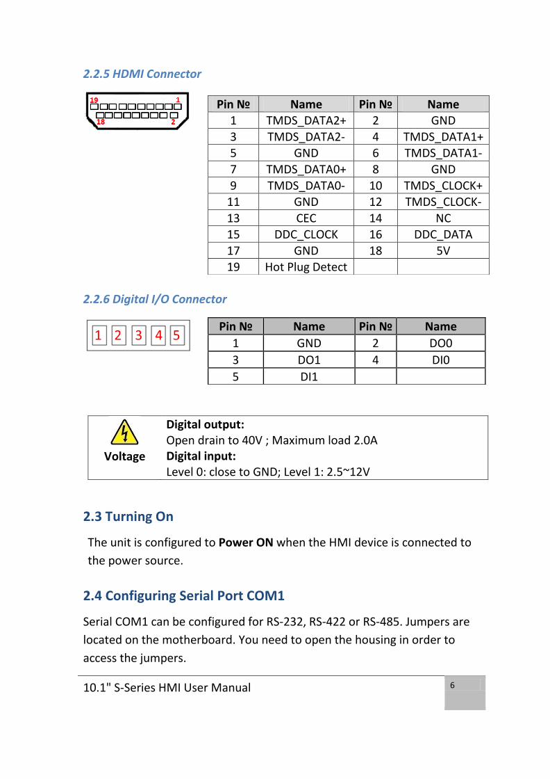
2.2.5 HDMI Connector
2.2.6 Digital I/O Connector
2.3 Turning On
The unit is configured to Power ON when the HMI device is connected to
the power source.
2.4 Configuring Serial Port COM1
Serial COM1 can be configured for RS-232, RS-422 or RS-485. Jumpers are
located on the motherboard. You need to open the housing in order to
access the jumpers.
Pin № Name Pin № Name 1 TMDS_DATA2+ 2 GND
3 TMDS_DATA2- 4 TMDS_DATA1+ 5 GND 6 TMDS_DATA1-
7 TMDS_DATA0+ 8 GND
9 TMDS_DATA0- 10 TMDS_CLOCK+ 11 GND 12 TMDS_CLOCK-
13 CEC 14 NC 15 DDC_CLOCK 16 DDC_DATA
17 GND 18 5V 19 Hot Plug Detect
Pin № Name Pin № Name
1 GND 2 DO0
3 DO1 4 DI0
5 DI1
Voltage
Digital output: Open drain to 40V ; Maximum load 2.0A Digital input: Level 0: close to GND; Level 1: 2.5~12V

10.1" S-Series HMI User Manual
7
CAUTION/ ATTENTION It is recommended to use factory jumper settings. Opening the housing when it is sealed may damage the device and its parts. Il est recommandé d’utiliser la configuration d’usine de cavalier. Ouvrir le chassis lorsqu’il est scellé peut endommagé l’appareil et ses pièces.
Note:
A pair of needle nose pliers may be helpful when working with
jumpers. If you have any doubts about the best hardware
configuration for your application, contact your local distributor
or sales representative before you make any changes.
Generally, you simply need a standard cable to make most
connections.
The jumper setting diagram is shown below. When the jumper cap is placed on both pins, the jumper is SHORT. The illustration below shows a 3-pin jumper; pins 1 and 2 are short. If you remove the jumper cap, the jumper is OPEN.
Both Jumper 8 and Jumper 9 allow setting the Serial Port COM1
configuration. Refer to the table below for PIN assignment.
RS-232 RS-422 RS-485
JP8 1-2 3-4 5-6
JP9 1-2
4-5
7-8
10-11
2-3
5-6
8-9
11-12
2-3
5-6
8-9
11-12

10.1" S-Series HMI User Manual
8
The picture below shows RS-232/422/485 (J8/J9) jumper setting.
Example: To make RS-232 Settings, set the Jumper 8 Pin 1-2 to the SHORT
position, and Jumper 9 Pin1-2, 4-5, 7-8, 10-11 to the SHORT position.
2.5 Turning Off
You can Turn OFF the HMI device with the Windows power settings.
To shut down the device:
1. Tap Start > Shut down.
2. Wait for your HMI device to completely turn off before disconnecting the
power cord (if necessary).

10.1" S-Series HMI User Manual
9
Operating the Device This chapter provides detailed information on how to operate the device. If you have been using touch-screen Panel PCs before, the interface may look familiar. Sections include system settings parameters.

10.1" S-Series HMI User Manual
10
3 Operating the HMI Device
In this chapter you will find instructions on how to operate the HMI device with Hot Tab.
3.1 System Settings
3.1.1 Hot Tab Menu
1. Double-click the Hot Tab icon on the Windows desktop.
2. The Hot Tab main menu will appear on the screen as shown below.
3.1.2 Utilities
Utilities category allows automatically changing orientation from landscape
to portrait mode or rotating the desktop to a different degree as 0°, 90°,
180°, and 270°.
3.1.3 Brightness
Tap Brightness button to show current brightness level.
To reduce the brightness, drag by touch to left.

10.1" S-Series HMI User Manual
11
To enhance the brightness, drag by touch to right.
Tap Close to save the changes and exit the interface.
3.1.4 Volume
Tap this button to show your current volume level.
To decrease the volume, drag by touch to left side.
To increase the volume, drag by touch to right side.
3.1.5 LED Light Bar (Easy-Testing)
Tap this button to access the LED light bar control panel, and select Red /
Green / Blue/ Orange color to be displayed on the LED Bar.

10.1" S-Series HMI User Manual
12
3.1.6 Performance
User can adjust the performance level of the HMI device. There are four
options available:
Extreme performance
Office Document
High performance
Power Saving
3.1.7 Touch Lock
To LOCK touch screen, double-click the Hot Tab icon on the Windows
desktop, and tap Touch Lock.
To UNLOCK Touch Screen, tap button to the right.
3.1.8 HF RFID
HF RFID is commonly used for ticketing, payment, and data transfer
applications.
The RFID Reader is located on the bottom right front side of the HMI device.
, the COM Port setting in RFID Reader is “COM 14”

10.1" S-Series HMI User Manual
13
1. Double-click the RFID icon on the Windows desktop.
2. Reader menu appears on the screen as shown below.
Reader Demo Version 1.04
The RFID Reader can read and write data according to different HF RFID
Note:
The picture below of Reader Demo Version 1.4 is for illustration
purposes only. Your Reader version may differ from the picture
below.

10.1" S-Series HMI User Manual
14
standards.
HF RFID Standard Purpose
ISO-14443 A Standard for MIFARE technology, which used
in smart cards and proximity cards
ISO-15693 Standard for tracking items
ISO-18092 Standard for Near Field Communication (NFC),
a short range technology that is commonly
used for data exchange between devices
P2P/NDEF NFC Data Exchange Format
Read Mode
Select the default RFID Reader COM14 or press Search on the upper left
corner of the screen. The system will automatically find RFID COM port,
show the Version.
UID0 Menu
The system will read the data once the card will be near. You can select
different reader modes. Each mode is described below.
Item
№
Key button Function
3 *A0- Continuous
Read
The RFID Reader will perform a series of
multiple scanning operations
4 A1- Once Read The RFID Reader will perform a single scanning
operation during the card is near
5 A9- Type Read The RFID Reader will perform a scanning
operation of IC type tag
* Default
Item
№
Key button Function
1 E1- Version Displays the current version of RFID Reader
system
2 E2- Reset Reset all settings

10.1" S-Series HMI User Manual
15
To scan the card, bring it close to the right bottom front side of device with
RFID icon.
№ Data 32 Function
6 XXXXXXXXXXXXXABCDEF Display the information written in the card

10.1" S-Series HMI User Manual
16
Write Mode
Refer to the RFID Porting Guide SDK to configure Write Mode parameters.
3.2 Operating System
S-series HMI support several versions of Windows OS: Windows 10 IoT,
Windows Embedded 8.1 Industry Pro, Windows Embedded 8 Standard,
Windows 7 Pro for Embedded Systems, and Windows Embedded Standard
7 – WS7P.
IMPORTANT:
The device is shipped with the OS System according to your
order. Contact us if you have any questions regarding OS
settings.

10.1" S-Series HMI User Manual
17
Driver Installation This chapter describes how to install all necessary drivers.

10.1" S-Series HMI User Manual
18
4 Driver Installation
This chapter provides guideline to driver installations.
4.1 Installing Chipset Driver
Step 1 Insert the CD that comes with the motherboard. Open the file
document “Chipset Driver” and click “infinst_auto.exe” to install driver.

10.1" S-Series HMI User Manual
19
Step 2 Click Next to continue.
Step 3 Click Yes to agree the license terms.

10.1" S-Series HMI User Manual
20
Step 4 Click Next to install the driver.
Step 5 Software setup progress window will appear, click Next to continue.
Step 6 Click “Yes, I want to restart this computer now” to finish the
installation.

10.1" S-Series HMI User Manual
21
4.2 Installing Graphics Driver
Step 1 Insert the CD that comes with the motherboard. Open the file
document “Graphics Driver” and click Setup to execute the setup.
Step 2 Setup Welcome Window will appear, click Next to continue the
process.
Step 3 Carefully read the license terms and click Yes to agree.
Step 4 Check Readme file information, and click Next to install driver.
Step 5 Click Next to continue.
Step 6 Windows Security window will appear, click “Install this driver
software anyway” to continue.
Step 7 Setup Progress window will appear, click Next to continue the
installation.
Step 8 Setup is complete, click “Yes, I want to restart this computer now”
to finish the installation and restart the computer.

10.1" S-Series HMI User Manual
22
4.3 Installing Intel Sideband Fabric Device (Intel MBI) Driver
(Windows 8)
Step 1 Insert the CD that comes with the motherboard. Open the file
document “MBI” and click “Setup.exe” to install the driver.
Step 2 Welcome to the setup program window will appear, click Next to
start the installation.
Step 3 Carefully read the License Agreement terms and click Yes to agree.
Step 4 Setup progress will appear, please wait for the operations to be
performed, then click Next to continue.
Step 5 The installation is complete, click “Yes, I want to restart this
computer now” to finish and restart the computer.

10.1" S-Series HMI User Manual
23
4.4 Installing Intel Trusted Engine Interface (Intel TXE) Driver
Step 1 Insert the CD that comes with the motherboard. Open the file
document “TXE” and click “Setup TXE.exe” to install the driver.
Step 2 Welcome to the setup program window will appear, click Next to
start the installation.
Step 3 Carefully read the license terms and click Yes to agree.
Step 4 Confirmation window will appear, click Next to continue the driver
installation.
Step 5 Please wait while the product is being installed.
Step 6 The installation is complete, click Finish to complete the installation
and restart the computer.

10.1" S-Series HMI User Manual
24
4.5 Installing Intel Network Connections
User must confirm the type of operating system is being used before
installing Intel Network Connections. Follow the steps below to
complete the installation.
Step 1 Click “PROWin64.exe”
Step 2 Click Yes to start the installation.
Step 3 Welcome window will appear, click Next to install the driver.
Step 4 In the program maintenance window you will see two options
available. “Remove” is to remove Intel Networks Connections from your
computer, and “Modify” is to make any changes. Choose Modify to
continue.
Step 5 In the Setup Options window choose “Intel® PRO Set for Windows®
Device Manger”, “Intel ® Network Connections SNMP Agent” and
“Advanced Network Services”.
Step 6 The wizard is ready to begin installation, click Install to continue.
Step 7 Install wizard completed, click Finish to complete the installation.

10.1" S-Series HMI User Manual
25
4.6 Installing Audio Driver
The ALC886 series are high-performance 7.1+2 channel high definition
audio codecs that provide ten DAC channels for simultaneous support of
7.1 sound playback, plus 2 channels of independent stereo sound output
(multiple streaming) through the front panel stereo outputs. The series
integrates two stereo ADCs that can support a stereo microphone, and
feature Acoustic Echo Cancellation (AEC), Beam Forming (BF), and Noise
Suppression (NS) technology.
Step 1 Insert the CD that comes with the motherboard. Open the file
document “Audio Driver” and click “Setup.exe” to install the driver.
Step 2 Please wait while the InstalShield Wizard prepares the setup.
Step 3 Welcome window will appear, click Next to install the driver.
Step 4 It might take some time to configure new software installation.
Please wait.
Step 5 Windows security will appear, click Install to install the audio driver.
Step 6 The installation is complete, select “Yes, I want to restart my
computer now”, and click Finish to complete the installation.

10.1" S-Series HMI User Manual
26
4.7 Installing USB 3.0 Driver (Windows 7)
NOTE:
If your operation system is Windows Embedded 8.1 Industry or
Windows Embedded 8 Standard, you should skip the USB 3.0
driver installation.
This HMI features Intel Celeron Bay Trail-M N2930 CPU with the Intel® USB
3.0 extensible Host Controller. You need to install the Intel® USB 3.0
extensible Host Controller driver to enable the function.
Step 1 Locate the hard drive directory where the driver files are stored with
the browser or the explore feature of Windows*.
Step 2 Double-click the “Setup.exe” from this directory.

10.1" S-Series HMI User Manual
27
Step 3 Welcome window will appear, Click Next to install the driver.
Step 4 Carefully read the license terms and click Yes to agree.
Step 5 Review Readme file information and click Next to continue the
installation.
Step 6 When the Setup Progress is complete click Next to continue.
Step 7 Click “Yes, I want to restart this computer now” to finish and then
restart your computer.

10.1" S-Series HMI User Manual
28
BIOS Setup
BIOS Setup Utility is a program for
configuration basic Input / Output system
settings of the HMI for optimum use. This
chapter provides information on how to use
BIOS setup, its functions and menu.

10.1" S-Series HMI User Manual
29
5 BIOS Setup
5.1 When and How to Use BIOS Setup
To enter the BIOS setup, you need to connect an external USB keyboard,
press <Del> key when the prompt appears on the screen during start up.
The prompt screen shows only few seconds, you need to press <Del> key
quickly. If the message disappears before your respond, restart the system
by turning it OFF and ON, and enter the BIOS again.
IMPORTANT:
Updated BIOS version may be published after the manual
released. Check the latest version of BIOS on the website.
Run BIOS setup utility for:
1. Error message on screen indicates to check BIOS setup
2. Restoring the factory default settings.
3. Modifying the specific hardware specifications
4. Necessity to optimize specifications

10.1" S-Series HMI User Manual
30
5.2 BIOS Functions
BIOS Navigation Keys
BIOS navigation keys for keyboard control are listed below.
The following keys are enabled during POST:
Key Function
Del Enters the BIOS setup menu.
F7 Display the boot menu. Lists all bootable devices that are
connected to the system. With cursor ↑and cursor ↓and
by pressing <ENTER>, select the device used for the boot.
Pause Pressing the [Pause] key stops the POST. Press any other
key to resume the POST.
The following Keys can be used after entering the BIOS Setup.
Key Function
F1 General Help
F2 Previous Values
F3 Optimized Defaults
F4 Save & Exit
Esc Exit
+/- Change Opt.
Enter Select or execute command
Cursor ↑ Moves to the previous item
Cursor ↓ Goes to the next item
Cursor ← Moves to the previous item
Cursor → Goes to the next item
NOTE:
You can press the F1, F2, F3, F4, –/+, and Esc keys by connecting
a USB keyboard to your device.

10.1" S-Series HMI User Manual
31
5.2.1 Main Menu
When you enter BIOS setup, the first menu that appears on the screen is
the main menu.It contains the system information including BIOS version,
processor RC version, system language, time, and date.
Immediately after the [DEL] key is pressed during startup, the main BIOS
setup menu appears:

10.1" S-Series HMI User Manual
32
BIOS
Setting
Description Setting Option Effect
System
Language
Displays the system
language. [English]
is set up by default.
Adjustment of the
language
Set the language in
other language. The
language in this
device is English.
System
Date/Time
This is current date
setting. The time is
maintained by the
battery when the
device is turned
off.
Date and time
changes.
Set the date in the
format
[mm/dd/yyyy];
The time in the
format:
[hh/mm/ss]
Access
Level
The current user
access settings
Changes to the
level of access
Administrator is set
up by the default
5.2.2 Advanced Menu
The advanced menu also uses to set configuration of the CPU and other
system devices. There are sub menus on the left frame of the screen.
IMPORTANT: Handle advanced BIOS settings page with caution. Any changes can affect the operation of your computer.
For items marked ► press <Enter> for more options.
Advanced Configuration and Power Interface (ACPI) settings allow to
control how the power switch operates. The power supply can be adjusted
for power requirements. You can use the screen to select options of ACPI
configuration. A description of the selected items will appear on the right
side of the screen.

10.1" S-Series HMI User Manual
33
BIOS Setting Description Setting
Option
Effect
ACPI Settings Configures ACPI settings Enter Opens
submenu
F81866 Super IO
Configuration
Configures IO settings Enter Opens
submenu
Hardware Monitor Configures Hardware
Monitor settings
Enter Opens
submenu
S5 RTC Wake
Settings
Configures RTC Wake
parameters
Enter Opens
submenu
CPU Configuration Configures CPU settings Enter Opens
submenu
PPM Configuration Configures PPM settings Enter Opens
submenu
Thermal
Configuration
Configures Thermal
Parameters
Enter Opens
submenu

10.1" S-Series HMI User Manual
34
IDE Configuration Configures IDE
Parameters
Enter Opens
submenu
Miscellaneous
Configuration
Configures
Miscellaneous
Parameters
Enter Opens
submenu
CSM Configuration Configures CSM
Parameters
Enter Opens
submenu
USB Configuration Configures USB Settings Enter Opens
submenu
Platform Trust
Technology
Configures Platform
Trust Technology
parameters
Enter Opens
submenu
Security
Configuration
Configures Security
parameters
Enter Opens
submenu
For items marked ► press <Enter> for more options.
5.2.2.1 ACPI Settings Advanced Configuration and Power Interface (ACPI) settings allow to
control how the power switch operates. The power supply can be adjusted
for power requirements. You can use the screen to select options of ACPI
configuration. A description of the selected items will appear on the right
side of the screen.

10.1" S-Series HMI User Manual
35
BIOS Setting Description Setting
Option
Effect
Enable ACPI Auto
Configuration
BIOS ACPI
Auto
Configuration
Enable/
Disable
Enables or
Disables this
function
Enable
Hibernation
Control
hibernation
Enable/
Disable
Enables or
Disables this
function

10.1" S-Series HMI User Manual
36
5.2.2.2 F81866 Super IO Configuration
You can use the screen to select options for Super IO Configuration, and
change the value of the option selected. A description of the selected item
appears on the right side of the screen.
For items marked with ►, please press <Enter> for more options.
Serial Port 1~5
Use these items to set parameters related to serial port 1~5.

10.1" S-Series HMI User Manual
37
Watch Dog Time Select
You can either disable Watch Dog Time Select, or set up the time.Use
<Arrow> keys to navigate and please press <Enter> to select the item.
GPI0 Port Configuration
You can use the screen to change GPI0 Port setting. Use these items to set
parameters related to PIN3-PIN14 Control.

10.1" S-Series HMI User Manual
38
5.2.2.3 Hardware Monitor
You can check PC Health Status parameters such as system temperature,
fan speed etc.
5.2.2.4 S5 RTC Wake Settings
Wake system from S5 enables or disables system wake on alarm event.
It allows you to wake up the system in a certain time.

10.1" S-Series HMI User Manual
39
Wake System from S5 with fixed time setting
Select Fixed Time to set the system to wake on the specified time.
Use Navigation Keys to switch among the items: Day, Hour,
Minute and Second. Type the desired value in the selected item.
For example: If you want the system to start up automatically at 15:30:30,
the 10th day of each month, then you should enter 10, 15, 30, and 30 from
top to bottom.

10.1" S-Series HMI User Manual
40
Wake system from S5 after dynamic time setting Select Dynamic Time to set the system to wake on the current time +
increase minute (s).
5.2.2.5 CPU Configuration

10.1" S-Series HMI User Manual
41
BIOS Setting Description Setting
Option
Effect
Socket CPU Information
This item contains socket specific CPU information.
Enter Open sub-menu
CPU Thermal Configuration
Thermal control Enter Open sub-menu
Limit CPUID Maximum
Limits CPIID Maximum Disabled/Enabled
Enable/Disable this function
Execute Disable Bit
Execute Disable Bit Disabled/Enabled
Enable/Disable this function
Intel Virtualization Technology
Allows to run recent OS and applications
Enabled/Disabled
Enable/Disable this function
Power Technology
Control the performance and power management functions of the processors
Disabled Disable this function
Energy Efficient
Enable energy efficient mode
5.2.2.6 PPM Configuration

10.1" S-Series HMI User Manual
42
BIOS Setting Description Setting
Option
Effect
CPU C State
Report
Shows CPU C State
Report
Enabled/
Disabled
Enable or Disable
CPU C state report
to OS
Max CPU C-
State
Allows to enter power-
saving mode in order
to save energy
C1E, C3,
C6, C7,
Auto
Enable or Disable
CPU C Max CPU S-
Sate

10.1" S-Series HMI User Manual
43
5.2.2.7 Thermal Configuration
This menu allows controlling thermal settings of the computer. Refer to the
descriptions on the top right side of the screen for detailed information
about each setting.
BIOS Setting
Description Setting Option Effect
Critical Trip Point
Specifies the temperature at which the OS will shut down the system
90C, 87C, 85C, 79C, 71C, 63C,55C,47C, 39C, 31C, 23C, 15C
Select the disable temperature for the system to shut down
Passive Trip Point
Specifies the temperature at which the OS will begin adjusting the processor
90C, 87C, 85C, 79C, 71C, 63C,55C,47C, 39C, 31C, 23C, 15C
Select the disable temperature for the system to start adjusting the processor

10.1" S-Series HMI User Manual
44
5.2.2.8 IDE Configuration
BIOS Setting
Description Setting Option
Effect
Serial- ATA (SATA)
Responsible for supporting chipset drives with SATA interface.
Enabled/ Disabled
Enable or disable this function
SATA Speed Support
Allows forcing the speed limit SATA II ports standard IDE / SATA-controller chipset.
Gen1 The maximum speed will be limited to 150 MB/s
Gen2 The maximum speed will be limited to 300 MB/s
Disabled Disables manual configuration of SATA II ports (mode will be selected based on the specifications of

10.1" S-Series HMI User Manual
45
connected drives)
SATA Mode This option specifies the operation mode of modern IDE / SATA-controller chipset
[AHCI] Selecting this option allows you to take full advantage of the extended host controller SATA II
[IDE] SATA controller will operate in a mechanism similar to a conventional IDE-controller
[RAID] Allows combining hard drives in RAID-arrays in order to improve the reliability of data storage, or to increase the speed.
Serial- ATA Port 0
The option turns on or off Port 0 of SATA channels of standard IDE / SATA-controller chipset.
Enabled/ Disabled
Turn on (Enabled) or turn off (Disabled) Port 0
SATA Port0 HotPlug
This feature that allows you to attach and remove a SATA Port0
Enabled/ Disabled
Enable or disable this function
Serial- ATA Port 1
The option turns on or off Port 1 of SATA channels of standard IDE / SATA-controller chipset.
Enabled/ Disabled
Turn on (Enabled) or turn off (Disabled) Port 1
SATA Port1 HotPlug
This feature that allows you to attach and remove a SATA Port1
Enabled/ Disabled
Enable or disable this function

10.1" S-Series HMI User Manual
46
5.2.2.9 Miscellaneous Configuration OS Selection
This item allows users to select the proper Operating System.
BIOS Setting Description Setting
Option
Effect
Windows 8.X Allows user to choose the
proper OS.
Enter Use Windows 8.X
Windows 7 Allows user to choose the
proper OS.
Enter Use Windows 7
IMPORTANT:
The device will be shipped with OS according to your order.
BIOS OS Selection menu varies accordingly.

10.1" S-Series HMI User Manual
47
5.2.2.10 CSM Configuration
BIOS Setting
Description Setting Option
Effect
CSM Support
The Compatibility Support Module (CSM) is a component of the UEFI firmware that provides legacy BIOS compatibility by emulating a BIOS environment, allowing legacy operating systems and some option ROMs that do not support UEFI to still be used.
Enabled/ Disabled
Enable or disable the Compatibility Support Module
GetaA20 Active
Activate GetaA20 Upon Request
Enable or disable this function
Option ROM Messages
Receiving ROM Messages Settings
Force BIOS
Set ROM messages parameters

10.1" S-Series HMI User Manual
48
Network Specifies which Network option ROM is booted
UEFI Only UEFI option ROMs are booted
Legacy
Storage Specifies which Storage option ROM is booted
UEFI Only UEFI option ROMs are booted
Legacy Only Legacy option ROMs are booted
Video Specifies which Video option ROM is booted
UEFI Only UEFI option ROMs are booted
Legacy Only Legacy option ROMs are booted
Other PCI Devices
Specifies which option ROM is booted for devices other than the network, storage or video
UEFI Only UEFI option ROMs are booted
Legacy Only Legacy option ROMs are booted
5.2.2.11 USB Configuration

10.1" S-Series HMI User Manual
49
BIOS Setting
Description Setting Option
Effect
Legacy USB Support
User can enable or disable USB port.
Disable Will keep USB devices available only for EFI applications.
Enable Enable all the USB devices
USB 3.0 Support
User can enable or disable USB 3.0 (XHCI) controller support.
Enable Enable USB 3.0 is enable
Disable USB 3.0 is disable
XHCI Hand‐off
This is a workaround for OSs without XHCI hand‐ off support.
Disable Disables this function
Enable Enables this function
EHCI Hand‐off
This is a workaround for OSs without ECHI hand‐ off support.
Disable Disables this function
Enable Enables this function
USB mass storage driver support
User can Enable or disable USB mass storage driver support.
Disable Disables this function
Enable Enables this function
USB Transfer time‐ out
The time‐out value for control, bulk, and interrupt transfers.
1 Sec 5 Sec 10 Sec 20 Sec
Depends on the time‐out value
Device Reset time‐ out
USB mass storage device start unit command time‐ out.
10 Sec 20 Sec 30 Sec 40 Sec
Depends on the time‐out value
Device power‐up delay
Maximum time the device will take before it properly reports itself to the host controller.
Auto Uses default value: for a root port it is 100 ms, for a Hub port the delay is taken from Hub descriptor

10.1" S-Series HMI User Manual
50
5.2.2.12 Platform Trust Technology
BIOS Setting Description Setting Option Effect
fTPM Trusted Platform Module
parameters
Enabled/Disabled Enables or
disables this
function

10.1" S-Series HMI User Manual
51
5.2.2.13 Security Configuration
BIOS Setting Description Setting
Option
Effect
TXE Trusted Execution
Technology parameters
Enabled/
Disabled
Enables or disables
this function
TXE HMRFPO TXE HMRFPO parameters Enabled/
Disabled
Enables or disables
this function
TXE Firmware
Update
TXE Firmware Update
parameters
Enabled/
Disabled
Enables or disables
this function
TXE EOP
Message
TXE EOP Message
parameters
Enabled/
Disabled
Enables or disables
this function
Intel ® AT Intel ® AT parameters Enabled/
Disabled
Enables or disables
this function
Intel ® AT
Platform PBA
Intel ® AT Platform PBA
parameters
Enabled/
Disabled
Enables or disables
this function

10.1" S-Series HMI User Manual
52
5.2.3 Chipset Menu
For items marked with ►, please press <Enter> for more options.
BIOS Setting
Description Setting Option
Effect
High Precious Timer
Allow to set up High Precious Timer settings
Enabled/ Disabled
Enables/Disables this function
Restore AC Power Loss
This function allows to set up booting options after a power failure
Power on/ Power off
Boot automatically after a power failure
Serial IRQ Mode
When working with personal computer hardware, installing and removing devices, the system relies on interrupt requests. Interrupt request
Continuous Allow user to set up desired IRQ Mode

10.1" S-Series HMI User Manual
53
5.2.4 Security Menu
In the Security menu, users can set administrator password, user password,
and HDD security configuration.
BIOS Setting Description Setting
Option
Effect
Administrator
Password
Displays whether or not an
administrator password has
been set.
Enter Enter
password
User Password Display whether or not a user
Password has been set.
Enter Enter
password

10.1" S-Series HMI User Manual
54
5.2.5 Boot Configuration
The Boot menu sets the sequence of the devices to be searched for the
operating system. The bootable devices will be automatically detected
during POST and shown here, allowing you to set the sequence that the
BIOS uses to look for a boot device from which to load the operating
system.

10.1" S-Series HMI User Manual
55
BIOS Setting Description Setting Option
Effect
Setup Prompt Timeout
Allows user to configure the number of seconds to stay in BIOS setup prompt screen.
Enter Set the prompt timeout
Boot NumLock State
Enables or disables NumLock feature on the numeric keypad of the keyboard after the POST (Default: On).
On Remains On
Off Remains OFF
Quite Boot Determines if POST message or OEM logo (default = Black background) is displayed.
Disabled Disables this function
Enabled Enables this function
Fast Boot Enables or disables Fast Boot to shorten the OS boot process. (Default: Disabled).
Disabled Disables this function
Enabled Enables this function
Boot Mode Select
Specifies which mode will be used for booting
Legacy Only Legacy option is booted
UEFI Only UEFI option is booted
Boot Option #1~#6
Specifies the overall boot order from the available devices
Ex: Boot Option#1 (hard drive)
Hard drive as the first priority
USB Key Drive BBS Priorities
USB Key Drive BBS Priorities Enter Open sub-menu
Hard Disk Drive BBS Priorities
Hard Disk Drive BBS Priorities Enter Open sub-menu
Network Drive BBS Priorities
Network Drive BBS Priorities Enter Open sub-menu

10.1" S-Series HMI User Manual
56
5.2.6 Save & Exit
The Exit menu displays a way how to exit BIOS Setup utility. After finishing
your settings, you must save and exit for changes to be applied.
BIOS
Setting Description Setting
Option Effect
Save Changes and Exit
This saves the changes to the CMOS and exits the BIOS Setup program.
Enter <YES>
Save changes
Discard Changes and Exit
This exits the BIOS Setup without saving the changes made in BIOS Setup to the CMOS.
Enter <YES>
Saves the changes
Enter <NO>
Return to the BIOS Setup Main Menu
Save Changes and Reset
Reset the system after saving the changes.
Enter <YES>
Saves the changes
Enter <NO>
Return to the BIOS Setup Main

10.1" S-Series HMI User Manual
57
Menu
Discard Changes and Reset
Reset system setup without saving any changes
Enter <YES>
Saves the changes
Enter <NO>
Return to the BIOS Setup Main Menu
Save Changes
Save changes done so far to any of the setup options.
Enter <YES>
Saves the changes
Enter <NO>
Return to the BIOS Setup Main Menu
Discard Changes
Discard changes done so far to any of the setup options.
Enter <YES>
Saves the changes
Enter <NO>
Return to the BIOS Setup Main Menu
Restore Default
Restore/load default values for all the setup options.
Enter <YES>
Saves the changes
Enter <NO>
Return to the BIOS Setup Main Menu
Save as User Defaults
Save the changes done so far as User defaults.
Enter <YES>
Saves the changes
Enter <NO>
Return to the BIOS Setup Main Menu
Restore User Defaults
Restore the User Defaults to all the setup options.
Enter <YES>
Saves the changes
Enter <NO>
Return to the BIOS Setup Main Menu

10.1" S-Series HMI User Manual
58
5.3 Using Recovery Wizard to Restore Computer
Note:
Before starting the recovery process, make sure to backup all
user data. The data will be lost after the recovery process.
To enable quick one-key recovery procedure:
Plug-in the AC adapter to Bay Trail series computer. Make sure the
computer stays plugged in to power source during the recovery
process.
Turn on the computer, and when the boot screen shows up, press
the F6 to initiate the Recovery Wizard.
The following screen shows the Recovery Wizard. Click Recovery
button to continue.
A warning message about data loss will show up. Make sure the data is
backed up before recovery, and click Yes to continue.

10.1" S-Series HMI User Manual
59
Wait the recovery process to complete. During the recovery process, a
command prompt will show up to indicate the percent of recovery process
complete. The system will restart automatically after recovery completed.

10.1" S-Series HMI User Manual
60
Mounting Solutions
This chapter provides step-by-step
mounting guide for all available mounting
options.

10.1" S-Series HMI User Manual
61
6 Mounting Solutions
This chapter provides mounting guide for all available mounting options. Pay attention to cautions and warning to avoid any damages.
6.1 Cable Mounting Considerations
For a nice look and safe installation, make sure cables are neatly hidden
behind the HMI device. Refer to Chapter 2, section 2.1 for the Cable
Installation instruction.
CAUTION/ ATTENTION Observe all local installation requirements for connection cable type and protection level. Suivre tous les règlements locaux d’installations, de câblage et niveaux de protection.
CAUTION/ ATTENTION Turn off the device and disconnect other peripherals before installation. Éteindre l’appareil et débrancher tous les périphériques avant l’installation.
ALTERNATING CURRENT / MISE À LE TERRE! To prevent electrical shock, the Safety Ground location on the rear must be bonded to the local earth ground through a minimum 12 AWG wire as short as possible Pour éviter les chocs électriques, l’emplacement de la prise terre à l’arrière doit être lié à terre locale, à travers un 12 AWG minimum et aussi court que possible.

10.1" S-Series HMI User Manual
62
5.2 Safety Precautions
Observe the following common safety precautions before installing any
electronic device:
• Use separate, non-intersecting paths to route power and
networking wires. If power wiring and device wiring paths must be
crossed make sure the wires are perpendicular at the intersection
point.
• Keep the wires separated according to the interface. Wires that
share similar electrical characteristics must be bundled together.
• Do not bundle input wiring with output wiring. Keep them separate.
When necessary, it is strongly advised that you label wiring to all
devices in the system.
5.3 Mounting Guide
S-series HMI devices come with different mounting options suitable for
most of the industrial and commercial applications. The main mounting
approach is chassis - very user-friendly in terms of installation. Refer to sub-
sections below for more details.
5.3.1 VESA Mount
• Dimensions: 75 x 75mm
• Screw hole diameter: VESA M4 x 5mm
• Compatible with swimming arms mounting kits.
*with customer’s bracket

10.1" S-Series HMI User Manual
63
Mounting Steps:
1. Screw VESA Bracket to the fixture (ex. wall) with M4 flat-head screws.
2. Place the device on VESA bracket.
NOTE:
Please notice that both hooks on bracket should lock
the notches on the back cover of the device.
5.3.2 Flush Mount / Panel Mount
• Wall cut-out: 157.6 x 249mm
• Screw hole diameter: M3 x 4mm
Mounting Steps:
1. Prepare a fixture for the specific dimensions of the device
2. Cut a hole on a sub frame or panel according to the cut-out
dimensions 157.6 x 249mm
3. Install the device properly onto the cut-out area of the sub frame or
panel with the sides of the front bezel
NOTE:
Please make sure that the eight holes on gasket can fit in the
mounting holes on the device.
4. Fix the device to fixture with eight M3 screws

10.1" S-Series HMI User Manual
64
5.4 Optional Mounting Solutions
5.4.1 Front Side Wall Mount
The device can be mounted in the wall.
Wall cut-out: 275 x 184mm
Screw hole diameter: M4 x 5mm
Mounting Steps:
1. Cut a hole in the wall according to the cut-out dimensions
275 x 184mm
2. Attach the bezel with clips to the device, fix the bezel with M4 screws
3. Connect the device to the power source with the power cord
4. Install the device properly onto the in-wall cut-out area;
fix the device using the clips

10.1" S-Series HMI User Manual
65
5.4.2 Desk Stand
The device can be installed on a desk with the stand. You can purchase desk
stand as an optional accessory.
Screw Hole Diameter: M4 x 5 mm
Mounting Steps:
Use provided M4 screws to fix the desk stand to VESA holes on the
back cover of the device.

10.1" S-Series HMI User Manual
66
Technical Support
This chapter includes information where to
find technical support.
10.1" S-Series HMI User Manual
67
7 Technical Support
This chapter includes information where to find technical support and Winmate’s Software Developing Kit (SDK). If any problem occurs fill in Problem Report Form enclosed and immediately contact us.
7.1 Software Developer Support
We provide the SDK in the User Manual and SDK CD , or you can download the SDK from Winmate Download Center or Winmate Partner Portal. 7.1.1 Digital I/O SDK
To find the Digital I/O Sample code, please contact us.
7.1.2 Watchdog SDK
To find the Watchdog Sample code, please contact us.
7.1.3 LED Light Bar Porting Guide
Please find the SDK file in User Manual and SDK CD or download from below 1. Winmate Download Center:
http://www.winmate.com.tw/ > Support > Download Center > Multi-Touch
PPC > W10IB3S-PCH2 > Development Kit > LED Light Bar SDK
Follow the link below:
http://www.winmate.com.tw/DownCenter/DownLoadCenter.asp?DownType=3005
2. Winmate Partner Portal http://www.winmate.com.tw/ > Support > Partner Portal > Public Documents > Panel PC > Multi-Touch HMI > S-Series HMI > IB32 > SDK > LED Light Bar SDK 7.1.4 RFID Porting Guide
Please find the SDK file in User Manual and SDK CD or download from below 1. Winmate Download Center:
http://www.winmate.com.tw/ > Support > Download Center > Multi-Touch
PPC > W10IB3S-PCH2 > Development Kit > RFID SDK
Follow the link below:
http://www.winmate.com.tw/DownCenter/DownLoadCenter.asp?DownType=3005&OnlyContent=
2. Winmate Partner Portal http://www.winmate.com.tw/ Support > Partner Portal > Public Documents > Panel PC > Multi-Touch HMI > S-Series HMI > IB32 > SDK > RFID SDK

10.1" S-Series HMI User Manual
68
7.2 Problem Report Form
10.1" S-Series HMI (Slim-line)
Customer name:
Company:
Tel.: Fax:
E-mail: Date:
Product Serial Number: __________________________________________
Problem Description: Please describe the problem as clearly as possible.
Detailed description of the occurred problem will allow us to find the best
solution to solve the problem as soon as possible.
______________________________________________________________
______________________________________________________________
______________________________________________________________
______________________________________________________________
______________________________________________________________
______________________________________________________________
______________________________________________________________
______________________________________________________________
______________________________________________________________
______________________________________________________________
______________________________________________________________
______________________________________________________________
______________________________________________________________
______________________________________________________________
______________________________________________________________
______________________________________________________________
______________________________________________________________
______________________________________________________________
______________________________________________________________
_____________________________________________________________

10.1" S-Series HMI User Manual
69
Certificates
This chapter includes FCC and EC
Declarations of Conformity.

10.1" S-Series HMI User Manual
70
8 Certificates
This chapter includes FCC and EC Declarations of Conformity.
8.1 FCC Declaration of Conformity
8.1.1 W10IB3S-PCH2AC-PoE

10.1" S-Series HMI User Manual
71
8.1.2 W10IB3S-PCH2AC-POE

10.1" S-Series HMI User Manual
72
8.2 EC Declaration of Conformity
8.2.1 W10IB3S-PCH2AC-PoE
Refer to Preface for letters abbreviations in English and other languages.

10.1" S-Series HMI User Manual
73
8.2.2 W10IB3S-PCH2AC-POE
Refer to Preface for letters abbreviations in English and other languages.

Winmate Inc. 9F, No.111-6, Shing-De Rd., San-Chung City, Taipei 241, Taiwan, R.O.C Tel: 886-2-8511-0288 Fax: 886-2-8511-0211 Email: [email protected] Official website: http://www.winmate.com.tw