100%Report - EML 4905 - Team 2 (J.Gutierrez-A.Nunez-D ...
134
Fall 2012 EML 4905 Senior Design Project A B.S. THESIS PREPARED IN PARTIAL FULFILLMENT OF THE REQUIREMENT FOR THE DEGREE OF BACHELOR OF SCIENCE IN MECHANICAL ENGINEERING Development of a Formula SAE Body 100% Report Javier Gutierrez Angel Nuñez Diego Quintero Advisor: Professor Andres Tremante April 12, 2013 This B.S. thesis is written in partial fulfillment of the requirements in EML 4905. The contents represent the opinion of the authors and not the Department of Mechanical and Materials Engineering.
Transcript of 100%Report - EML 4905 - Team 2 (J.Gutierrez-A.Nunez-D ...

Fall 2012
EML 4905 Senior Design Project
A B.S. THESIS PREPARED IN PARTIAL FULFILLMENT OF THE
REQUIREMENT FOR THE DEGREE OF BACHELOR OF SCIENCE
IN MECHANICAL ENGINEERING
Development of a Formula SAE Body 100% Report
Javier Gutierrez Angel Nuñez Diego Quintero
Advisor: Professor Andres Tremante
April 12, 2013
This B.S. thesis is written in partial fulfillment of the requirements in EML 4905. The contents represent the opinion of the authors and not the
Department of Mechanical and Materials Engineering.

Page ii
Ethics Statement and Signatures
The work submitted in this B.S. thesis is solely prepared by a team consisting of Javier
Gutierrez, Angel Nuñez, and Diego Quintero and it is original. Excerpts from others’ work
have been clearly identified, their work acknowledged within the text and listed in the list
of references. All of the engineering drawings, computer programs, formulations, design
work, prototype development and testing reported in this document are also original and
prepared by the same team of students.
Javier Gutierrez
Team Leader
Angel Nuñez
Team Member
Diego Quintero
Team Member
Dr. Andres Tremante
Faculty Advisor

Page iii
Table of Contents
Ethics Statement and Signatures ....................................................................................................................... ii
Table of Contents ..................................................................................................................................................... iii
List of Figures ........................................................................................................................................................... vi
List of Tables ............................................................................................................................................................. ix
Abstract ........................................................................................................................................................................ 1
1. Introduction ....................................................................................................................................................... 2
1.1 Problem Statement .................................................................................................................................. 2
1.2 Motivation ................................................................................................................................................... 3
1.3 Literature Survey ..................................................................................................................................... 3
2. Project Formulation ....................................................................................................................................... 6
2.1 Project Objectives .................................................................................................................................... 6
3. Design Alternatives ......................................................................................................................................... 6
3.1 Overview of Conceptual Designs Developed ................................................................................ 6
3.2 Alternative Designs: Platform ............................................................................................................ 7
3.2.1 Design Alternate I .................................................................................................................................... 7
3.2.2 Design Alternate II ................................................................................................................................... 7
3.2.3 Design Alternate III ................................................................................................................................. 8
3.3 Alternative Designs: Materials ........................................................................................................... 9
3.4 Feasibility Assessment .......................................................................................................................... 9
3.5 Proposed Design ..................................................................................................................................... 10
4. Engineering Design and Analysis ........................................................................................................... 11
4.1 Analytical Analysis ................................................................................................................................ 11
4.2 Body Analysis ........................................................................................................................................... 11
4.3 Side Pod Analysis ................................................................................................................................... 11
4.4 Ground Effect Analysis ......................................................................................................................... 12

Page iv
4.5 Structural Design .................................................................................................................................... 14
4.6 Cost Analysis ............................................................................................................................................ 16
5. Prototype Construction ............................................................................................................................... 18
5.1 Description of Prototype ..................................................................................................................... 18
5.2 Initial Prototype Cost Analysis ......................................................................................................... 19
5.3 Cost Acknowledgements ..................................................................................................................... 20
5.4 Revised Cost Analysis ........................................................................................................................... 20
6. Simulations and Evaluation ...................................................................................................................... 22
6.1 Overview .................................................................................................................................................... 22
6.2 Finite Element Analysis (FEA) .......................................................................................................... 23
6.3 Computational Fluid Dynamics (CFD) .......................................................................................... 27
6.4 Improvements of Design ..................................................................................................................... 33
6.4.1 Body Designs ............................................................................................................................................ 33
6.4.2 Diffuser Designs ...................................................................................................................................... 34
7. Manufacturing ................................................................................................................................................. 42
7.1 Process Overview ................................................................................................................................... 42
7.2 Mold Creation .......................................................................................................................................... 42
7.2.1 Material Selection .................................................................................................................................. 42
7.2.1.1 Foam Characteristics ................................................................................................................. 44
7.2.2 Body Sectioning ...................................................................................................................................... 45
7.2.2.1 CNC Router Limitations ............................................................................................................ 45
7.2.2.2 Sectioning of Body ...................................................................................................................... 46
7.2.3 Conversion to MasterCam .................................................................................................................. 47
7.2.4 CNC Milling ............................................................................................................................................... 48
7.2.5 Attachment of Molds ............................................................................................................................. 49

Page v
7.3 Mold Preparation ................................................................................................................................... 50
7.3.1 Material Selection .................................................................................................................................. 50
7.3.2 Initial Sanding and Repairs ................................................................................................................ 50
7.3.3 Initial Compound Layering ................................................................................................................ 51
7.3.4 Second Compound Layering .............................................................................................................. 52
7.4 Carbon Fiber Laying .............................................................................................................................. 54
7.5 Release and Finish ................................................................................................................................. 56
7.6 Juncture and Attachment .................................................................................................................... 58
7.7 Design Considerations ......................................................................................................................... 58
7.8 Safety Considerations ........................................................................................................................... 60
8. Project Management .................................................................................................................................... 61
8.1 Overview .................................................................................................................................................... 61
8.2 Breakdown of Work into Specific Tasks ...................................................................................... 61
8.3 Organization of Work and Timeline ............................................................................................... 62
8.4 Breakdown of Responsibilities ........................................................................................................ 63
9. Conclusion ........................................................................................................................................................ 64
9.1 Conclusion and Discussion ................................................................................................................ 64
9.2 Recommendations and future work .............................................................................................. 64
10. References ...................................................................................................................................................... 66
11. Appendices .................................................................................................................................................... 68
Appendix A. Technical Drawings ................................................................................................................ 69
Appendix B. Formula SAE Body Rule Book ......................................................................................... 106
Appendix C. Quotes ........................................................................................................................................ 124
Appendix D. Apparatus ................................................................................................................................ 125

Page vi
List of Figures
Figure 1: 2011-‐2012 FIU-‐FSAE Prototype .................................................................................................... 2
Figure 2: GPR 2011-‐2012 Vehicle ..................................................................................................................... 3
Figure 3: Design Alternative 1 ............................................................................................................................ 7
Figure 4: Design Alternative 2 ............................................................................................................................ 8
Figure 5: Design Alternative 3 ............................................................................................................................ 8
Figure 6: Proposed Design ................................................................................................................................. 10
Figure 7: Air Flow ................................................................................................................................................... 12
Figure 8: Ground Effects ...................................................................................................................................... 13
Figure 9: First Iteration Diffuser Design, Isometric View ..................................................................... 13
Figure 10: First Iteration Diffuser Design, Bottom View ...................................................................... 14
Figure 11: Structural Design ............................................................................................................................. 15
Figure 12: Rendering of Final Body, Sidepods and Diffuser Design ................................................. 18
Figure 13: Load and Restrains .......................................................................................................................... 23
Figure 14: Body Material Properties ............................................................................................................. 23
Figure 15: Material Properties ......................................................................................................................... 24
Figure 16: Mesh Information ............................................................................................................................ 24
Figure 17: Structural Rigidity ........................................................................................................................... 24
Figure 18: Body Displacement ......................................................................................................................... 25
Figure 19: Von Misses Stress ............................................................................................................................. 25
Figure 20: Displacement ..................................................................................................................................... 26
Figure 21: Frame Torsional Rigidity, Front View ..................................................................................... 26
Figure 22: Frame Torsional Rigidity, Perspective View ........................................................................ 27
Figure 23: Fluid Conditions ............................................................................................................................... 28

Page vii
Figure 24: Pressure Analysis ............................................................................................................................. 28
Figure 25: Temperature Analysis .................................................................................................................... 29
Figure 26: Velocity Analysis .............................................................................................................................. 29
Figure 27: Drag Coefficient ................................................................................................................................ 30
Figure 28: Diffuser Transparent Isometric View ..................................................................................... 30
Figure 29: Diffuser Sectioned Side view ....................................................................................................... 31
Figure 30: Diffuser Bottom View ..................................................................................................................... 32
Figure 31: Diffuser Rear View ........................................................................................................................... 32
Figure 32: First Iteration Body Design ......................................................................................................... 33
Figure 33: Second Iteration Body Design .................................................................................................... 33
Figure 34: Third and Final Iteration Body Design ................................................................................... 34
Figure 35: Velocity, First Iteration Model .................................................................................................... 35
Figure 36: Velocity, Second Iteration Model .............................................................................................. 35
Figure 37: Velocity, Third Iteration Model .................................................................................................. 36
Figure 38: Velocity, Fourth Iteration Model ............................................................................................... 36
Figure 39: Velocity, Fifth and Final Iteration Model ............................................................................... 37
Figure 40: Pressure, First Iteration Model .................................................................................................. 37
Figure 41: Pressure, Second Iteration Model ............................................................................................. 38
Figure 42: Pressure, Third Iteration Model ................................................................................................ 38
Figure 43: Pressure, Fourth Iteration Model ............................................................................................. 39
Figure 44: Pressure, Fifth and Final Iteration Model .............................................................................. 39
Figure 45: Final Diffuser Rendering ............................................................................................................... 40
Figure 46: 2013 FIU-‐SAE Prototype, Final Rendering ........................................................................... 41
Figure 47: ISO-‐C1/2.0 Foam .............................................................................................................................. 44
Figure 48: Techno CNC ........................................................................................................................................ 46

Page viii
Figure 49: Body Sections .................................................................................................................................... 47
Figure 50: Assembly of Body Sections .......................................................................................................... 48
Figure 51: CNC Milling ......................................................................................................................................... 49
Figure 52: Nose Half Right Section ................................................................................................................. 49
Figure 53: Nose With Gaps Repaired ............................................................................................................. 50
Figure 54: Wood Glue Brushing ....................................................................................................................... 51
Figure 55: First Orange Tooling Gelcoat Layer ......................................................................................... 52
Figure 56: Tooling Gelcoat After Sanding .................................................................................................... 53
Figure 57: Test Sample with Release Agents ............................................................................................. 54
Figure 58: Application of Clear Gelcoat ........................................................................................................ 55
Figure 59: Layering of Carbon Fiber .............................................................................................................. 56
Figure 60: Unmolding of Part ............................................................................................................................ 57
Figure 61: Carbon Fiber Final Part ................................................................................................................. 57
Figure 62: Body Sub-‐Sections ........................................................................................................................... 59
Figure 64: Gantt chart .......................................................................................................................................... 62
Figure 65: Ground Effects ................................................................................................................................... 71
Figure 66: Body – Left Wall Extension .......................................................................................................... 73
Figure 67: Body – Left Wall ................................................................................................................................ 75
Figure 68: Body – Nose Bottom ....................................................................................................................... 77
Figure 69: Body – Nose LC .................................................................................................................................. 79
Figure 70: Body – Nose LL .................................................................................................................................. 81
Figure 71: Body – Nose RC ................................................................................................................................. 83
Figure 72: Body – Nose RR ................................................................................................................................. 85
Figure 73: Body – Rear Floor ............................................................................................................................ 87
Figure 74: Rear Hood ............................................................................................................................................ 89

Page ix
Figure 75: Body – Right Wall Extension ....................................................................................................... 91
Figure 76: Body – Right Wall ............................................................................................................................. 93
Figure 77: Body – Sidepod Left -‐ Bottom ..................................................................................................... 95
Figure 78: Body – Sidepod Left -‐ Side ............................................................................................................ 97
Figure 79: Body – Sidepod Left -‐ Top ............................................................................................................ 99
Figure 80: Body – Sidepod Right -‐ Bottom ............................................................................................... 101
Figure 81: Body – Sidepod Right -‐ Side ...................................................................................................... 103
Figure 82: Body – Sidepod Right -‐ Top ...................................................................................................... 105
Figure 83: Techno CNC LC4896 Series ...................................................................................................... 125
List of Tables
Table 1: Competition Events [11] ..................................................................................................................... 5
Table 2: Cost Analysis [7] ................................................................................................................................... 16
Table 3: Current Hours Spent ........................................................................................................................... 17
Table 4: Prototype Cost Analysis [6] ............................................................................................................. 19
Table 5: Final Cost Analysis ............................................................................................................................... 21
Table 6: Drag Force ............................................................................................................................................... 30
Table 7: Foam Properties ................................................................................................................................... 45
Table 8: Breakdown of Responsibilities ....................................................................................................... 63
Table 9: Fiberglass Coating Quote ............................................................................................................... 124

Page 1
Abstract
The team will develop the exoskeleton body structure and its respective ground
effects for the Florida International University Formula SAE segment, taking into account
several factors to present an optimum body model as a final result. These factors include,
but are not limited to, weight, cost, wind drag resistance, functionality and aesthetics.
The following project is divided into three phases, design (or modeling), analysis and
manufacturing. First, on the design stage, a rough hand sketch of the vehicle will be made.
Then, a mock-‐up of the vehicle body and diffuser will be modeled in SolidWorks.
Subsequently, several iterations of shapes and sizes will be modeled. Finally, a design is
going to be chosen based on the results of phase two, and the final optimization needs to be
performed. For phase two, analysis, several body designs are going to be initially tested
using SolidWorks as the preferred CAD software due to the convenience of easy
availability. Both Finite Elements Analysis (FEA) and Computational Fluid Dynamics (CFD)
simulations will be performed to ensure the best performance of the final design chosen
based on some previously set goals. For the third stage, manufacturing, first several molds
are going to be machined in sections due to the apparatus limitations on ISO-‐C1, two pound
density foam using a CNC routing machine, then sanded, glued and assembled together and
then prepared in order to lay the carbon fiber. The preparation consists on doing an initial
coat of orange tooling to harden and show imperfections on the molds. Later, the molds
will be repaired and leveled with lightweight putty on critical areas following several coats
of the tooling gelcoat to harden the gelcoat and left to dry for 24 hours. Later, after sanding
the grooves left by the spraying of tooling gelcoat, several coats of sealer, polishing
compound, and other release agents will be used to ensure a smooth mold, which
translates to a smooth and nice looking part. Subsequently, a HI-‐UV clear gelcoat is going to
be sprayed for shininess and left to dry; the carbon fiber will then be laid onto the molds
and saturated with Vinylester resin, the layers will then be removed to reveal the final
product. Finally after carefully choosing an optimal design and after the completion of its
manufacturing, the physical body will be tested in the FIU WOW wind tunnel.

Page 2
1. Introduction
1.1 Problem Statement
The Florida International University Formula SAE (FSAE) team wanted to build their
second prototype vehicle for the 2013 FSAE competition. Due to the complexity of this
project, several sub-‐teams are needed in order to develop a competitive car. Each of these
sub-‐teams will take full responsibility of each system of the vehicle (i.e. Engine, Drivetrain,
Brakes, Suspension, Electrical, Body and Frame). One of the biggest defects of last year’s
car, shown in Figure 1, was the body that was built. It was a last minute design and
manufacturing mainly because of the lack of human power and knowledge on the matter.
Also, no analyses were done respecting the study of aerodynamics and poor attention was
given to weight, functionality and esthetics. Therefore, the scope of this project will be the
development of a much-‐improved body for the FIU Formula SAE 2012-‐2013 prototype.
Figure 1: 2011-‐2012 FIU-‐FSAE Prototype
The principal limitation will be time since the vehicle will be participating in the
Collegiate Design Series: Formula SAE competition to be held in Brooklyn, Michigan on May
8th, 2013. Therefore, the vehicle has to be completely finished several weeks before the
competition date for overall testing. Another important factor to take into consideration, as
a limitation, is funding. Mainly, personal out-‐of-‐pocket expenses will be minimized. Some of

Page 3
the measures taken to support this objective include the development of a sponsorship
proposal to approach companies. Some of the benefits for companies include: exposure,
since the vehicle will be competing in a national event; tax deduction, since FIU-‐SAE is a
non-‐profit organization with a Tax-‐ID number; and, the fact that they will be supporting
future engineers with great passion for the automotive industry. Another source of income
will be to attend several fundraising events hosted by FIU-‐SAE.
1.2 Motivation
Based on the results of last year’s competition, one of the major proposed
improvements for the upcoming prototype was a proper body design. By approaching this
task as a Senior Design Project, it would allow for a better and more in-‐depth analysis of
the matter that would yield an optimal design. Our team decided to tackle this project as it
involves various advanced concepts from different fields of engineering, such as: Fluid
Dynamics, Structural Analysis, Mechanics of Materials and Computer Aided Design.
1.3 Literature Survey
In order to develop a highly competitive body for a Formula SAE application, first, the
2012 competition winner vehicle needs to be examined. The Oregon State university team
has won several competitions in the past few years, therefore, is a great candidate to be
analyzed.
Figure 2: GPR 2011-‐2012 Vehicle

Page 4
Before analyzing its body, a brief explanation about GFR will be provided. “Global
Formula Racing is the first innovative global collaboration of its kind in the history of both
the US-‐based Formula SAE and EU-‐based Formula Student programs. The former BA
Racing Team from the Duale Hochschule Baden-‐Württemberg-‐Ravensburg (DHBW-‐R),
Germany, and the Beaver Racing Team from Oregon State University (OSU) have combined
forces to compete as a single entity. The two universities share physical and intellectual
resources to create a highly competitive vehicle worthy of international reputation.” [9]
The GFR team uses a carbon fiber monocoque as its frame and body. The body also
provides a structural rigidity to mount the rest of the systems of the car. This solutions
yield to a tremendous amount of weight savings, but its application is very expensive and
requires a lot of human resources. Due to the complexity of this application and the limited
budget of the FIU-‐SAE team, the scope of our project will be limited to developing of a
carbon fiber body. More details about this will be explained further in this report.
Several concepts need to be explained before further elaboration on the chosen
design project. First of all, Society of Automotive Engineers (SAE) International is a global
association of more than 128,000 members worldwide. SAE provides a standard in the
aerospace, automotive and commercial-‐vehicle industries [11]. Moreover, SAE hosts
various student competitions: Baja, Formula, Super Mileage, among others. Secondly,
Formula SAE (FSAE) is a project approached mainly by engineering students in which they
have to develop an open wheel, open cockpit small Formula-‐style racecar. This racecar, is
to be evaluated for its potential as a production item in an international competition with
over 120 Universities from around the world participating. Students have to research,
design, manufacture, test, develop, and manage production of their school’s prototype. This
competition is divided into two main type of events, Statics and Dynamics. Each of these
events has several categories of different evaluation weighs. The details are provided in
Table 1, as shown below:

Page 5
Table 1: Competition Events [11]
Type of Event Category Points
Static Events
Presentation 75 Engineering Design 150 Cost Analysis 100
Dynamic Events
Acceleration 75 Skid-‐Pad 50 Autocross 150
Fuel Economy 100 Endurance 300
Total Points 1,000
Lastly, FIU-‐SAE is a group of diverse people with a strong passion for the automotive
industry and is mainly composed by engineering students that represent the Florida
International University Chapter of the Society of Automotive Engineers worldwide. With
their second prototype ever built, FIU-‐SAE is striving to compete and thrive in the 2013
Formula SAE competition. The main purpose of this organization is to further develop the
engineering concepts learned in class, and provide a hands-‐on experience with an actual
object to successfully develop integral engineers for the future.

Page 6
2. Project Formulation
2.1 Project Objectives
To develop a body and its respective ground effects for the new prototype with the
proper studies and analysis, taking into account several factors to present an optimum
body model as a final result. These factors include, but are not limited to, weight, cost, drag
resistance, functionality and aesthetics. The expected product is to be appealing to the eye
and it will increase the performance of the vehicle. Additional objectives include being able
to accommodate the budget while maintaining a highly competitive level to perform well in
the competition. Furthermore, other objectives relates to improvements of past designed
bodies. The first generation of the FIU Formula car was made from fiberglass and its
surface was not very smooth. The new design will reduce the weight of the prototype and
as well as the air drag, taking into consideration the ground effects desired to be
implemented in the vehicle as a crucial factor. Moreover, the new body will be easier to
dismantle reducing the service time.
Another fundamental objective will be participating in the 2013 Formula SAE
competition to be held in Michigan in June 2013. Therefore, not only will this project have
to satisfy the class requirements but also it has to follow and satisfy all of the rules set forth
by SAE International.
3. Design Alternatives
3.1 Overview of Conceptual Designs Developed
The designs that have been considered are thought to tackle the team’s main
concerns, which are wind drag coefficient and weight reduction in order to improve overall
vehicle performance. Also, we would like to incorporate some visual attraction with a light
but aerodynamic body design. This will give the vehicle a greater opportunity to score
higher with the judges in the upcoming competitions.

Page 7
3.2 Alternative Designs: Platform
3.2.1 Design Alternate I
The team’s first alternative has a more costly direction and would be an ideal design if
the extensive funds were available to the team. The design consists of a full body
monocoque body that would eliminate the use of a frame. This of course would eliminate
weight and would increase the overall rigidity of vehicle.
Figure 3: Design Alternative 1
3.2.2 Design Alternate II
The second design path is to build a hybrid monocoque. The team discussed how this
might affect the judges’ outlook on the design complexity but after further research we
discovered that it has been shown that complex is not always better. After extensive
consideration we decided that it was more beneficial to the FIU Formula SAE team for us to
design a single piece body that would be an exoskeleton to the teams’ space frame design of
choice, plus, it’s still a very costly solution.

Page 8
Figure 4: Design Alternative 2
3.2.3 Design Alternate III
Our third option was not much of a consideration as the only reason we would resort
to doing a space frame half-‐body prototype lays in our budget. This is very unlikely since a
budget cut would most likely affect our manufacturing procedure rather than the proposed
design. Nonetheless, we must consider even the most unlikely situations so that we are not
caught off guard if these were to happen.
Figure 5: Design Alternative 3

Page 9
3.3 Alternative Designs: Materials
Following the same idea explained on the overview of this section, our main goal is
performance and aesthetics of the vehicle to increase the scores given by the competition
judges. Therefore, as per our research there are three main types of materials used in
teams all from around the world. Aluminum, Fiberglass and Carbon fiber; all of these
materials have their pros and cons as per their properties and we didn’t want to get to
much into detail with these because it really depends on the team goals and ease of
availability. Aluminum was almost immediately discarded, because of how hard it is to
shape around an aerodynamic design. If we were to choose this material, we’ll have to go
with a more simple design with flat panels shaping the body. Fiberglass, although it is much
less costly than carbon fiber, it is a heavier, harder to work, and even dangerous material
due to its very explosive fracturing failure, plus it was used on last year’s prototype and it
didn’t present the expected characteristics. Therefore, the material of choice will be carbon
fiber due to its low density, durability, strength and aesthetics.
3.4 Feasibility Assessment
Some of these alternatives are very feasible. Design alternate III is very simple and
could implements the usage of cheaper materials for its fabrication. Due to the fact that the
problem was approached as a mean for the senior design class, an extra level of complexity
is going to be applied. The proposed design will be of a simple yet properly studied shape,
and the material of usage is going to be carbon fiber. Design alternate II and I are the least
feasible of all three designs. The main reason these design concepts are not going to be
applied is due to the fact that SAE-‐FIU has a limited budget. The development of a
monocoque structure for this application will cost approximately $10,000-‐$15,000 and last
year’s budget for the whole prototype was around $10,000. Therefore, these designs were
immediately disregarded. The proposed design will bring that balance of cost-‐effectiveness
to the table. The feasibility for this design is high, but since again the team dealing with a
limited budget, for last-‐resort a change in material selection from carbon fiber to fiber glass
or any other type of material might be the case.

Page 10
3.5 Proposed Design
Our proposed design is going to involve creating sectional carbon fiber parts that will
come together to create a formula body that would cover about 80% of the vehicle. This
design will allow easier access to key mechanical components and will make it easier to
configure different aerodynamic packages that we will add to the main body. It will also
allow for other additions like that of our fellow senior design students that are creating the
adjustable spoiler for this vehicle. Figure 6 shows the first iteration of the proposed design.
Figure 6: Proposed Design

Page 11
4. Engineering Design and Analysis
4.1 Analytical Analysis
As a design was selected, the body was divided into different sub-‐components for a
more in-‐depth approach. These features can be categorized separately as they are
governed by different physical principles. The three main components on the racecar are:
Body, Side Pods and Ground Effects.
4.2 Body Analysis
When designing the body of a racecar, the two main purposes for the geometry of
the body are to slice through air as efficient as possible and to channel airstreams to
desired locations to produce downforce. When we apply this force in specific locations of
the car, we can increase grip on the tires, thus improving performance.
The Bernoulli Principle can further explain the previously mentioned force. As seen
in racecar aerodynamics, this principle explains that a fluid flowing around an object can
experience changes in pressure. This is due to the fact that a slowing moving fluid will
create more pressure than a faster moving object. By controlling the shape of the object,
this change of pressure can force the body to a desired direction. The direct relationship
between curved streamlines and pressure differences was derived by Leonard Euler, which
states [5]:
𝑑𝑝𝑑𝑅 = 𝜌
𝑣!
𝑅
where R is the radius of curvature, p is the pressure, ρ is the density, and v is the velocity.
This formula shows that higher velocities and tighter curvatures create larger pressure
differentials.
4.3 Side Pod Analysis
The air that passed through the nose is then guided to the side of the car by the
splitter located just in front of the side pods. The design of side pod can smoothen out the
airflow that has been disturbed by front wheels. It separates the flow into two parts; one is

Page 12
directed into the side pod and other is diverted outside. The air passes through the smooth
surface of side pod with minimum drag force. It acts to block the airflow from hitting the
rear wheels. The direct hit of air on the wheels may create turbulent which disturbs the
whole airflow dynamics on the real part of car. The design makes the air to flows in
steadier ways. Besides, the installation of side pods increases the safety of the car, it is able
to stabilize the whole body of car and protects driver from side collisions. Air directed into
the side pod is also used to cool the engine; it acts like a radiator intake. This design is
essential to enhance the performance of engine and protect it from overheating [5].
Figure 7: Air Flow
4.4 Ground Effect Analysis
The term “ground effects” was first introduced in Formula 1 racing. Engineers
needed to figure it out a way to make the vehicle go faster without modifying the power of
the engine due to rules restrictions [3].
The ground effects general concept is relatively simple. Formula 1 engineers wanted
to obtain a low-‐pressure area beneath the car that when combined with the high pressure
above it, would create an amazing force pushing the car downwards. An under body
diffuser, was the proposed solution, acting as inverted airfoils, allowed the air that entered
the car's underbody to accelerate through a narrow mid-‐section between the car and the

Page 13
ground, therefore creating a low-‐pressure section. However, this previously discussed
design was not able to produce the desired ground effects therefore sealing its underside
section. While initially built out of brushes or plastic, the best solution was to create some
skirts running from the side of the body to maintain this pressure drop under the floor and
that way the ground effects will be maximized [3].
Figure 8: Ground Effects
Following these principles, figure 9 shows an isometric view of our first iteration
conceptual design of the diffuser, which will be located on the bottom of the vehicle. More
details about the design approaches used for this part will be explained later on.
Figure 9: First Iteration Diffuser Design, Isometric View

Page 14
Figure 10 shows the bottom view of the diffuser conceptual design.
Figure 10: First Iteration Diffuser Design, Bottom View
4.5 Structural Design
Prior to designing the body of the car, one has to understand the forces exerted on
in for optimal structural integrity. Racecars are subjected to extreme forces due to high
cornering, acceleration and drag. Taking into consideration forces like longitudinal torsion,
vertical bending, lateral bending and horizontal lozenging, is crucial since these forces will
directly affect the performance of the racecar.
The primary value that determines the performance of a racecar’s frame is stiffness.
When forces are being applied in opposite corners of the vehicle, the frame is subjected to
torsional loads. Racecar frames can deform when subjected to these torsional loads,
directly affecting the handling and performance of the car. Stiffness can be described as the
resistance of the frame to these torsional forces. Stiffness is usually measured in foot-‐
pounds per degree, and in a single degree of freedom follows the following governing
equation [5]:
𝑘 =𝐹𝛿

Page 15
Where F is the force applied to the particular body, and δ is the displacement
produced by the force.
Other forces considered such as lateral and vertical bending follow the same
principles. Vertical bending on the frame is usually produced by the weight of the driver
and other components such as the engine, transmission, etc. In the case of lateral bending,
it usually occurs when the vehicle is subjected to forces due to cornering. Other factors that
create lateral bending are road camber and side wind loads. All these factors have to be
considered during the preliminary design stages of the frame, as torsion stiffness is
generally very important, as total cornering traction is a function of lateral weight transfer.
Figure 11: Structural Design
The figure above shows the tubular space frame designed for the FSAE body. This
design had to comply with rigorous safety and performance rules stated by SAE. Factors
such as cockpit clearance, overall length and height, and driver dimensions, had to be
considered on top of the torsional loads previously discussed. Even though the design of
the space frame is out of the scope of our project, we consider necessary and pertinent
information anything related to it.

Page 16
4.6 Cost Analysis
The first step towards producing a carbon fiber body and diffuser is to create a mold
for it. The team decided that using foam and a 3-‐D CNC routing machine would produce the
best mold needed for this project. After the first mold is created it is brushed with wood
glue and then sprayed with orange tooling gelcoat. This will make a smooth surface where
the carbon fiber, resin and hardener will be laid but not before using several mold release
agents on the surface. A smoothing wax is then applied to the raw product and with some
slight sanding and waxing there will be a glossy and glamorous look that carbon fiber
produces. There are some costs that need to be accounted for the sake of engineering
budgeting but will not be accounted for in our student budget. Some of these cost include
the man-‐hours used for the project, the machinery used will have to be appraised,
professional advising and consultation expenses. The following chart will show this cost
analysis in more depth.
Table 2: Cost Analysis [7]
Extra Expenses Amount of Resources Cost per Resource Cost
Predictions Man Hours 180 Hrs. $45 $8,100
Air Compressor 1 $250 $250 3-‐D CNC Router 1 $2,500 $2,500 Hand Tools 1 $200 $200 Professional Consulting 4 Hrs. $80 $320
Total Extra Expense $11,370
Table 3 shown above illustrates the extensive extra expensive this project
would obscure if we didn’t have access to the machinery and Professors of FIU.

Page 17
Table 3: Current Hours Spent
Team Member Human Hours
Javier Gutierrez 77
Angel Nuñez 60
Diego Quintero 78
Total 215
Table 4 shown above illustrates the current human hours spent on this project

Page 18
5. Prototype Construction
5.1 Description of Prototype
This final prototype consists in of a low weight high strength exoskeleton body for
the FSAE team at the Florida International University. The design also has to be pleasing to
the eye since it will be judged in competition by a group of engineers from all over the
world. For these reasons we decided to take the path of carbon fiber composite, rather than
using fiberglass or even aluminum which will increase weight and compromise strength.
The research has shown than unlike earlier days, the carbon fiber composite is much more
affordable now, and the curing process is close to that of fiberglass. First we will need to
create a mold for the body, in our case with the complexity that a cockpit brings we will
have to mold two halves and later join them together. The a series of curing processes
explained in other sections will take place using carbon fiber sheets and curing them with
epoxy resin. The next step will be to cut off excess material and wax the surface to get a
shinny, eye appealing final shell. The hinges and frame connection point are then installed
onto the body as well as any additional parts such as side pods, spoilers and other elements
of that nature. Finally the body will be painted to the FSAE teams’ specifications and
connected to their vehicles frame.
Figure 12: Rendering of Final Body, Sidepods and Diffuser Design

Page 19
5.2 Initial Prototype Cost Analysis
The prototype materials mentioned below have been budgeted in order to create an
accurate sponsorship proposal. Although the man power, machinery and professional
consulting is provided by the team and professors of Florida International University a
detailed budget had to be formatted since our budget as student is reasonably low. A very
effective budgeting building procedure had to be placed in order to create a low cost high
quality product. As the following chart explains;
Table 4: Prototype Cost Analysis [6]
Materials Used Unit sold in Cost per Unit Quantity Total
Price Carbon Fiber Sheets 50 in X 1yd $39.60 per Yd 32 yds $1,267.20
Epoxy Resin gallons $40.2 per gal 10 gal $402 Polimer Resin gallons $40.2 per gal 10 gal $402
Composite Hardener gallons $40.2 per gal 6.6 gal $265.36 Polyurethane RTV mold
rubber gallons $40.3 per gal 10 gal $430
PVA #10 Mold Release gallons $15 per gal 6 gal $90 Nylon Bagging Film 50 in X 1yd $4.70 per yd 32 yds $150
Perforated Release Film 50 in X 1yd $5.60 per yd 32 yds $179.20 Sealant Tape rolls $6.50 per roll 8 rolls $52
Al. Vacuum Bag Connector unit $29.99 per unit 6 units $180
Styrene gallons $20 per gal 4 gal $80 Mixing Container Kit unit $45 per kit 2 kits $90 Application Brush Kit unit $28 per kit 2 kits $56 Application Rollers Unit $3 per unit 15 units $45 Utherane Foam kit $264 per kit 1 kit $264 3-‐D Printing hourly $80 12 hrs $960
Total Budget $4,912.70
As shown above, the investment of the project will be much more if the extra
expenses were added to the budget shared by this student team.

Page 20
5.3 Cost Acknowledgements
After hard work and countless hours of communicating over the phone with many
companies, we were able to considerably lower our manufacturing cost. Dyplast Products,
a polymer foam manufacturer, was kind enough to provide us with all the foam that we
needed for our molds. This foam was the material used by the CNC router that the FIU
architecture department very kindly and diligently allowed us to work with. As far the
composites go, we were not able to get sponsored for them. We did fight hard to get the
best prices and student discounts wherever possible, this was able to save us about 40% off
all materials cost. The help and insight that our engineering professors as well as
professors from other faculties provided us with is not measureable. We really could not
have done it without them.
5.4 Revised Cost Analysis
After immense research and countless hours in meetings with field professionals, as
well as several donations received from sponsors and all the support from FIU faculty
members. We were able to cut the original budget in almost 70% without sacrificing the
performance or appearance of the final product. The following table shows the details of
the cost of every material used for the construction of the prototype.

Page 21
Table 5: Final Cost Analysis

Page 22
6. Simulations and Evaluation
6.1 Overview
Testing for this design will first take place in the preferred CAD program for the
team’s senior design project, SolidWorks. There will be major testing components that will
be looked at, taking aerodynamic design testing as our priority since the body will have a
frame underneath and strength testing is not as crucial. Through the SolidWorks
FlowExpress feature will be able to simulate the aerodynamic features of the vehicle at
different speeds and with different ground effect components and accessories (Spoiler,
Diffuser, side pods, etc.). Our final and most important design testing will come from an
actual wind tunnel machine. The physical vehicle will be placed inside this machine and
tested a velocity much higher than the assumed maximum speed of the vehicle to ensure
durability and performance. Before and after every test run there will be a visual inspection
of all the components of the vehicle to check for any signs of structural failure.

Page 23
6.2 Finite Element Analysis (FEA)
Since the development of the frame of the vehicle is out of the scope of our project,
FEA will not be a major factor for our design. Nonetheless, the team wanted to leave this
report as a handbook for future FIU-‐SAE teams. Therefore, we approached the task of
designing a monocoque and do the respective simulations that can be later on used as
reference for future projects. Illustrated in the figures below are the results from the Finite
Element Analysis testing on the second iteration of the proposed body design. NOTE: the
space frame underneath the body is not included in test. It’ll be treated as a monocoque
design. The entire rear face of the body is held rigid during all tests. The simulated loads
are placed on the front suspension points on either side of the chassis. Predicting a total
weight of 590lbs, the following reacting forces were obtained for a 40:60 weight
distribution ratio vehicle:
Figure 13: Load and Restrains
For the thickness use of 1/4in a total mass of 53.0kg was found for the proposed
body design. Figure 14 shows the results found:
Figure 14: Body Material Properties
Figure 15 exemplifies the material properties for the proposed carbon fiber body
based on online research of previous Formula SAE teams:

Page 24
Figure 15: Material Properties
The information for the mesh used in the analysis is tabulated on figure 16:
Figure 16: Mesh Information
The analysis done yields a structural rigidity of 17,325 Nm/deg. The calculation for
this value is shown in figure 17:
Figure 17: Structural Rigidity

Page 25
Figure 18: Body Displacement
Figure 19: Von Misses Stress

Page 26
Figure 20: Displacement
The maximum displacement found in our design of value 4.76E-‐05m as shown in
figure 20, was used for the calculation of the structural rigidity shown in figure 17. After
the analysis, the lowest factor of safety (FOS) found in the proposed design was of 94.7.
Surpassing enormously the team goal for a factor of safety of 2.
Since the designed body and components will be later on attached to the frame
designed by the chassis manager of the FIU-‐SAE team, we considered revising their
structural analysis on the frame and considered its torsional rigidity and displacement
distortion with the applied loads to observe where the probable areas that we could mount
the body on could be located.
Figure 21: Frame Torsional Rigidity, Front View

Page 27
Figure 22: Frame Torsional Rigidity, Perspective View
After observing both of these figures and hosting several meeting with different FIU-‐
SAE technical managers, we were able to obtain around 15 possible points or areas that we
could mount both the body with sidepods and the diffuser to the frame without interfering
with any other system on the car and placing the designed body as tight as possible to the
frame to avoid any undesired movement.
6.3 Computational Fluid Dynamics (CFD)
The following simulation will be the most important to ensure the maximum
performance of the vehicle and it’ll be validated after a physical evaluation of the actual
vehicle on a wind tunnel. Illustrated in the figures below are the results from the
Computational Fluid Dynamics testing on the proposed body design. NOTE: the Space
frame underneath the body is not included in test for simplicity. After the FIU-‐SAE team
finalizes a fully functional assembly of all the components of the car, we can proceed to do a
CFD analysis of the entire vehicle
For this analysis air was selected as the fluid of choice since the car will be exposed
to the environment, and all the calculations are based on the vehicle reaching a maximum
velocity of 40mph or 17.88m/s as shown in figure 23. The calculation of the drag coefficient

Page 28
shown in figure 27 is based on a frontal reference area of 732.87 in^2 as found in the
proposed design.
Figure 23: Fluid Conditions
Figure 24: Pressure Analysis

Page 29
Figure 25: Temperature Analysis
Figure 26: Velocity Analysis

Page 30
Figure 27: Drag Coefficient
As shown in figure 27, a drag coefficient value of 0.32 was found in the proposed design
using a drag force of 31.16N as obtained in analysis done and shown tabulated in table 5.
Table 6: Drag Force
The next section to be analyzed is the Ground Effects of the vehicles, mainly
composed by a diffuser. The idea behind implemented a diffuser in a racecar, as mentioned
before, is to increase downforce to provide the vehicle with more traction. Therefore,
increasing its overall performance.
Figure 28: Diffuser Transparent Isometric View

Page 31
There are several recommendations that one should follow when designing a
diffuser according to our research. The main idea is to divide these components into two
sections. The front section will be designed with the purpose of the airflow to travel from
large to small cross-‐sectional area to increase its velocity avoiding flow separation. On the
second or rear section, it’ll be design with the opposite purpose. The airflow will travel
from small to large cross-‐sectional area to decrease the airflow velocity and create a low-‐
pressure zone below the car, which would yield a generation of downforce. Also, vortex
generators at the very end of the diffuser will aid with this resolution of creating a low-‐
pressure area. Then, the goal would be to get the airflow velocity at the very end of the
diffuser to match or be more or less of a value near the initial or inlet velocity [10].
Figure 29: Diffuser Sectioned Side view
As shown in figure 29, air will enter through the right side (Front section of the
vehicle) and it will exit through the left side. As well as the previous CFD analysis, air speed
was assumed to be at 40mph, which approximately represent the top speed that the vehicle
will get at the track. To further bring a realistic element into this calculation, a floor was
placed at 1-‐inch bellow the diffuser, which is the minimum ground clearance permitted by
the Formula SAE rules [11].

Page 32
Figure 30: Diffuser Bottom View
It can be appreciated on figure 30, that the design chosen follows the principles
recommended by the Race Car Vehicles dynamics book [10] in which the air enters at a
certain speed, in this case 40mph and as the cross-‐sectional area reduces in size the airflow
speed increases up to a maximum value of more than 100mph, then as the cross-‐sectional
area increases the airflow speed reduces to a value close to the inlet speed which is desired
as explained before. Figure 31 shows how the vortex generators cause turbulence in the
flow with a careful and thoughtful design to avoid airflow separation, which aid to create
that low-‐pressure area underneath the vehicle, which will have a direct impact on the
vehicle’s performance, by creating downforce.
Figure 31: Diffuser Rear View

Page 33
6.4 Improvements of Design
6.4.1 Body Designs
The body was re-‐designed several times based mostly on aesthetics and the FIU-‐SAE team
needs for the body to cover completely their frame design. The following pictures show the
progress of this iterative design:
Figure 32: First Iteration Body Design
Figure 33: Second Iteration Body Design

Page 34
Figure 34: Third and Final Iteration Body Design
6.4.2 Diffuser Designs
The original diffuser design was modified numerous times to ensure maximum
performance of the part and the lowest cost of manufacturing. Also, since the diffuser
directly affects the clearance of the vehicle with respect to the ground, per SAE rules the
prototype has to be able to travel one inch up and down with respect to the neutral
position of the car. Consequently, later on in the semester the suspension team had to re-‐
design its original shocks layout and positioning, the diffuser had to be modified
accordingly to allow proper suspension travel. After performing several CFD analyses on
various iterations of conceptual designs, as shown in the next pictures:

Page 35
Velocity:
Figure 35: Velocity, First Iteration Model
Figure 36: Velocity, Second Iteration Model

Page 36
Figure 37: Velocity, Third Iteration Model
Figure 38: Velocity, Fourth Iteration Model

Page 37
Figure 39: Velocity, Fifth and Final Iteration Model
Pressure:
Figure 40: Pressure, First Iteration Model

Page 38
Figure 41: Pressure, Second Iteration Model
Figure 42: Pressure, Third Iteration Model

Page 39
Figure 43: Pressure, Fourth Iteration Model
Figure 44: Pressure, Fifth and Final Iteration Model

Page 40
Even tough the modification of the diffuser to allow proper suspension travel,
originally affected negatively the performance of this part. It was re-‐design with the goal of
reducing the pressure at the bottom of the vehicle and to have an exit velocity with a value
similar to the inlet velocity. As it can be appreciated on both fifth iteration model for the
pressure and velocity CFD analysis, both of these goals were successfully achieved and the
performance of the part was even improved. An isometric view of the final product can be
appreciated in the next figure:
Figure 45: Final Diffuser Rendering
The final vehicle after manufacturing will utilize both of this design and several other
components that the FIU-‐SAE team is currently in the process of manufacturing. The
following pictures exemplify a rendering of what the final product will look like.

Page 41
Figure 46: 2013 FIU-‐SAE Prototype, Final Rendering

Page 42
7. Manufacturing
7.1 Process Overview
After completing the design and analysis stages, the following step is manufacturing.
The development of composite materials is an extensive process with a multiple number of
steps and considerations. In general, the process is usually the same but depending on the
application certain variables change. The entire manufacturing process is divided into four
main sections: Mold Creation, Mold Preparation, Release and Finish, and Juncture and
Attachment.
7.2 Mold Creation
Mold Creation is the first step into the manufacturing process. This step is one of the
most important because it will directly affect the amount of time that you are going to
spend on the remaining steps. Various considerations have to be taken into account to
determine the best way to create a mold. Factors such as design, size, manufacturing
limitations and time will lead to the optimal mold type.
The first consideration is to create either a male or female mold. The selection
between the two will be determined on the finish and shapes within the parts. When
creating composites from a mold, the surface with the smoother is the one in direct contact
with the mold. In certain cases this factor can be disregarded if the parts are going to be
painted or covered by other components. Since our project is focusing in aerodynamics
and the aesthetics of the vehicle, we need to achieve the smoothest surface possible. With
this is mind; the best mold type would be a female mold, which would yield the smoothest
surface on the outside of the racecar.
7.2.1 Material Selection
The second consideration that has to be analyzed is material selection. The mold is
basically a vessel from where the finish part will be released. There are a number of
different materials that can be used to create this vessel, but some have more advantages
than others based on the application. Materials such as fiberglass, wood and foam are
commonly used in the industry to construct composite molds.

Page 43
Fiberglass is generally used when the part needs to be duplicated from an existing
part. By laying fiberglass onto the original part, an exact negative can be created and later
used as the mold. A disadvantage of this material selection is that once it is created, it can
no longer be modified. Furthermore, creating a fiberglass mold requires more resources
and manufacturing time. In contrast, wood is inexpensive and easier to manufacture. The
disadvantage with this material is that most of the manufacturing would be handmade
which would defeat the purpose of the aerodynamics-‐based design.
In our particular case, the first variable that leads us to the optimal mold material is
the type of composite in use. Since we are using carbon fiber as our composite, and we
want the finish product to expose the composite weave, a material that provides the
smoothest surfaces needs to be selected. In addition, the mold has to be able to be modified
by hand when alterations are needed. With these two factors in mind, we can clearly
determine that the optimal material for our mold would be foam. Another factor that
determined the mold material was the tools used to create the surfaces. We used a CNC
router, which commonly mills through the type of foam selected.

Page 44
Figure 47: ISO-‐C1/2.0 Foam
7.2.1.1 Foam Characteristics
As foam was selected as our mold material of choice, we now had to determine the
specifics of the material. This type of material has a wide range of different properties and
uses for a number of applications. In our particular case, we needed a specific type of foam
that is easy to mill and sand, but maintains structural rigidity. After consulting with an
expert in the field, we determined that ISO-‐C1/2.0 Polyisocyanurate Insulation from
Dyplast Products was our best selection. This 2.0 lb/ft³ material is easy to handle,
relatively light, and structurally sound. The following figure shows more in-‐depth
properties of ISO-‐C1.

Page 45
Table 7: Foam Properties
Another advantage of this specific material is wide range of sizing options. ISO-‐C1 is
created on large blocks that can be later hot-‐wired to the customer’s specifications. In our
specific case, we were able to get 48” x 36” x 8 blocks of foam.
7.2.2 Body Sectioning
Now that the material and mold type have been selected, the body design has to be
adjusted to comply with the previous selections. As mentioned before, since we are using a
CNC router to mill the molds, we have to take into consideration the limitations from this
machine. Based on these factors, we can continue to section the entire body into separate
sub-‐sections.
7.2.2.1 CNC Router Limitations
After analyzing the advantages and disadvantages of using a CNC Router, we opted
to use the Techno LC Series 4896 provided by the FIU School of Architecture. With this
machine we would be able to accurately mill our designs into the foam mold. The first

Page 46
limitation that we encountered with this particular CNC Router was the dimensions of the
loading bed. These values dictate the maximum possible length and width of the material
used for the mold. After measuring these dimension, we determined that the mold could
not be any longer than 8 ft. and wider than 50 in. Another limitation that we encountered
was the maximum depth that the router can mill. As shown in figure 48, the router bit could
only mill 4 in. deep per mold. In addition, another limitation on the machine is the inability
to mill in three dimensions. By only being able to mill vertically, faces with negative
curvatures would not be able to be recreated. After taking into account all these limitations,
proper sectioning of the entire body was achieved.
Figure 48: Techno CNC
7.2.2.2 Sectioning of Body
Since the model was originally sectioned for serviceability reasons, we continued
with further sectioning to comply with the CNC router limitations.
Taking the ‘Nose’ sub-‐section as an example, we can further demonstrate how the
sectioning was applied. Splitting the nose through the middle was the first sectioning that
was implemented. If we were to use a single mold for this section, we would not be able to
lay the composite fibers for the top section of the nose. By sectioning the part in two, we
would be able to place the molds horizontally and lay the composite fibers from above. At
this stage the sections still did not comply with the CNC limitations, which meant that
further sectioning had to be applied.

Page 47
Figure 49: Body Sections
7.2.3 Conversion to MasterCam
Our body prototype was originally created in SolidWorks using surface modeling.
All these files have to be converted into a language that the CNC router can understand.
Generally, CNC routers follow a set a computational coordinates in order to create the
shapes and curvatures desired. For this reason, we have to be able to convert our surface
models into a language that the CNC router can understand. We initially converted the files
to ‘.iges’ format, to be able to open them in Rhino 3D. In this software we are able to create
a model of the female mold, by removing the model’s surface from rendered mold. Now
that we have the surfaces that we want to be created on the mold, we can now convert the
entire file to G-‐Code. By importing the file to MasterCam, this software can analyze the
surfaces and automatically create the coordinate system that the CNC router is going to use.

Page 48
Figure 50: Assembly of Body Sections
7.2.4 CNC Milling
After the proper language and files were created, we imported them to the CNC
router. Then the foam block was placed in the loading bed and locked into place. This
particular model of CNC has an integrated vacuum system that suctions the block against
the bed, keeping it in place during the entire process. Depending on the size of the mold,
the milling process would take between 30 – 50 minutes. Even though this process is
automated, constant supervision of the machine was required. As the bit mills through the
foam block, the residual dust starts collecting around the bit and other moving parts which
can cause jams and errors. To prevent this from happening, we constantly vacuumed
around the bit and other moving parts. After completing all the separate molds, a total of 21
hours were spent during the entire milling process.

Page 49
Figure 51: CNC Milling
7.2.5 Attachment of Molds
Once all the parts are milled, the following step is to join all the different sections
into the main components of the body. Two different factors have to be taken into account
during the attachment: optimal accuracy and mold structural integrity. Each component
mold has to be attached as accurately as possible to be able to continue the surface curves
from one section to the other. If this is not done correctly, the aerodynamic properties
created during the design process can be lost. As far as mold structural integrity, the final
mold has to be able to be handled and transported to different locations while maintaining
the curvatures intact. With these two factors in mind, we decided to attach each section
with rods and Liquid Nails. The rods would help keep the entire structure stable, while
Liquid Nails is the preferred adhesive for foams and insulation.
Figure 52: Nose Half Right Section

Page 50
7.3 Mold Preparation
Mold preparation is the second and most important step during the manufacturing
process of composites. This step will directly affect the final quality of the part and the
difficulty of part release. Mold preparation mainly consists of a large number of small steps
that will repair the mold surface for optimal performance.
7.3.1 Material Selection
Similarly to the Mold Creation step, material selection is very crucial during Mold
Preparation. Selecting the correct compounds will and amounts will ensure the desired
finish. Most of the materials selected for this project were polymer gelcoats and resins
processed with MEK-‐P hardeners.
7.3.2 Initial Sanding and Repairs
Before starting to apply the materials mentioned above, the foam mold has to be
prepped. As the molds were milled, the router left a number of grooves between each pass
of the bit. These grooves have to be manually sanded down to be able to maintain the
curvatures of the surfaces. Since the foam material selected has a density of 2.0 lb/ft³, the
sanding process is relatively easy. This process also had to be made after attaching the
mold sections to ensure continuance of the curves within the surfaces.
Figure 53: Nose With Gaps Repaired

Page 51
In addition, we were able to make initial repairs on areas were the CNC router did
not reach. As mentioned during the CNC Limitations, the router is not able to mill negative
curvatures. We encountered some of these issues with a small number of our foam molds.
The router incorrectly interpreted these negative curves by created gaps and cracks and
the end of each surface. Filling the gaps with lightweight bonding putty initially repaired
these undesired gaps. This compound was selected due to its properties after drying.
Bonding putty is easy to handle and optimal for sanding after it is applied.
7.3.3 Initial Compound Layering
After the mold was sanded and the gaps were repaired, we had to begin layering the
different compounds to prepare the mold. The first material that we used was wood glue.
We applied this material to be able to cover the pores within the foam. Two layers of wood
glue were applied to ensure even coverage throughout the part. A waiting time of 30-‐40
minutes between each layer had to be applied.
Figure 54: Wood Glue Brushing
After the wood glue was fully dried, we continued the layering process by applying
tooling gelcoat. This type of polyester gelcoat, also known as orange tooling, would create a
thin hardened layer of plastic once it is cured. To make this chemical reaction, the gelcoat

Page 52
has to be mixed with a hardener or catalyst. When polyester gelcoats and resins are use, an
MEK-‐P catalyst has to be used to initiate the chemical reaction. In this case, we needed to
mix 2% of MEK-‐P by vol of the amount of gelcoat used. This hardener raises the
temperature of the gelcoat to up to 120 F to begin the hardening stage. This process takes
from 10-‐12 hours to fully cure. Once the gelcoat is completely dry, we can further repair
the remaining gaps and pores that are still present on the surface. After the bonding
compound is applied again, the entire surface has to be sanded once more.
Figure 55: First Orange Tooling Gelcoat Layer
7.3.4 Second Compound Layering
The second compound layering begins after all the surfaces on the mold are
completely cured and sealed. During this stage, we apply more compounds with the goal to
improve the final finish of the surface. We begin by adding 3-‐4 more layers of orange
tooling to ensure a hardened surface. This amount of layers also allow for extensive
sanding to maintain a smooth finish. Once these layers are cured and sanded, we continue

Page 53
by polishing the surfaces. We started by applying two layers of sealer to make sure that all
the pores are coated. Once the sealer is cured, we continue by adding a layer of polish
compound. This would start adding shine and creating a smooth surface.
Figure 56: Tooling Gelcoat After Sanding
Now that the surface is smooth, we started adding compounds that would facilitate
the release of the part. We started by applying five layers of wax to the surface. We had to
wait 30 mins between each layer to allow the wax to settle. Once all the layers have been
applied, we continue by adding a mold release agent. We opted to use PVA as it would
ensure a smooth release without sacrificing surface finish. This release agent dries
generally quickly and is the final stage of the mold preparation step.

Page 54
Figure 57: Test Sample with Release Agents
7.4 Carbon Fiber Laying
The following step after prepping the mold was start laying the carbon fiber inside
the mold. In our case, we decided to use three layers of carbon fiber to keep a rigid body.
The process begins by spraying a polyester clear coat on the mold and letting it dry until
tacky.

Page 55
Figure 58: Application of Clear Gelcoat
Once the mold was ready, we started laying the first layer of carbon fiber and
pressing it into place. By placing it while the clear coat is tacky, the carbon fiber will slightly
adhere to the mold. Once the sheet was on the desired position we continued by applied
the first layer of polyester resin. Similarly to the orange tooling, this resin has to be
prepared by using the MEK-‐P catalyst. We used a brush to apply the resin, which helps to
reduce air pockets on the surface. This step is later on repeated for each of the following
carbon fiber layers. This process takes 24 hours to fully cure.

Page 56
Figure 59: Layering of Carbon Fiber
7.5 Release and Finish
One of the final steps of the process is the release and finish of the carbon fiber part.
Once the part was fully cured within the mold, we continued by carefully removing it. The
best way to release the part from the mold is by shooting compressed air between the part
and the mold. Afterwards, we can carefully start pulling the part from it. At this stage, the
part should come out shiny and smooth with a small out or residual PVA on top. This can be
easily removed by wiping it with a dry cloth.

Page 57
Figure 60: Unmolding of Part
Since the carbon fiber was laid with oversized dimensions we needed to trim the
edges. The best tool to accomplish this is an electric grinder. Once all the edges were
trimmed, we smoothed off the edges with a sander. In case of surface errors, can further
polish the surface to ensure a great finish.
Figure 61: Carbon Fiber Final Part

Page 58
7.6 Juncture and Attachment
Certain parts of the body were created separately due to manufacturing restrains.
Once the parts were completed, we continued by attaching the parts into main components.
To accomplish this, we created tabs around the areas that were going to be merged. The
tabs would later be glued with epoxy and carbon tap, and finally sanded and polished.
After all the junctures were created and all the separate parts were finished, the
final step was to attach the body to the frame of the racecar. We installed tabs around the
frame on specific locations to keep the body in place. Since this body has to be able to be
removed due to serviceability reason, quarter-‐turn fasteners were added to the body for
quick release. Finally, a detailed check-‐up of all components was performed and process
was finalized.
7.7 Design Considerations
After various iterations a final model was designed with the manufacturing process in
mind. As the design process was restarted, various components and measurements had to
be revised due to changes on the frame of the racecar. Since the engine’s intake system was
modified, the overall frame had to be extended to fit the new modifications. These changes
had to be taken into consideration when the final body model was designed. This iteration
was divided into three different sections for better analysis and ease of assembly: Body,
sidepods and ground effects.
The first section known as body, consist of the main portion of the model that covers
the cockpit and routes the airflow into the sidepods. Taking a more in-‐depth look at this
section, we further divided the model into different sub-‐sections: Nose, sub-‐body and
engine cover as shown in figure 62. The main factor that dictated the location of these
divisions was serviceability. The team has to be able to access the engine and suspension

Page 59
components with ease during the course of the race, and reducing body removal time is
crucial to do modifications efficiently.
Figure 62: Body Sub-‐Sections
As mentioned before, a secondary factor that affected the division process was
manufacturing. Since these components are going to be constructed with the use of molds,
certain constrains have to be taken into consideration. Certain shapes and curves cannot be
done using a single mold, so the design has to be further divided. An example of this issue
can be seen with nose sub-‐section. If we were to use a single mold for this section, we
would not be able to lay the composite fibers for the top section of the nose. To prevent this
problem, it was decided to divide the nose into two identical molds, which would later be
bonded together.
This method produces another manufacturing concern: How to properly bond to
composite parts together. We started to tackle this issue during the design process. As we
split the CAD model into their respective sections, we added tabs to the edges of each part
that would later fit onto each other. Afterwards, adhesive elements are added to these
sections to bond the pieces into one. Same design considerations were applied to the
sidepods and the diffuser in order to facilitate their manufacturing process.
Nose
Sub Body
Engine Cover

Page 60
7.8 Safety Considerations
Dealing with chemicals and hazardous materials is very dangerous, not to mention spending
hours at a time inside machine shops and workshops. The most safety procedures were followed. At
all times when dealing with high-‐density foam goggles and respirator mask were used. The
particles released by the foam are minimal in size and can be easily inhaled without the proper
care. In addition while using chemicals like epoxy resin and gel coats gloves had to be used in order
to protect our hands from harmful chemical reactions. These chemicals were never used near any
open flames and never left out in the sun were they could over heat and possibly ignite. Finally, as a
team we proud ourselves as strict followers of safety regulations in all labs and machine shops that
we worked in, and our zero incident project manufacturing reflects our dedication to safety.
Page 61
8. Project Management
8.1 Overview
Since several deliverables have to be turned in during the fall and spring semesters, a
key factor for this project will be planning and organization. Also, if the goals and objective
set forth for this project wants to be accomplished all the requirements from the senior
design class and SAE rules have to be successfully reached in a timely manner. For all of
these reasons a timeline, a breakdown of work into tasks and a breakdown of
responsibilities were developed.
8.2 Breakdown of Work into Specific Tasks
The Gantt chart shown in Figure 64 aids to act as an organizational tool for the team
to have strict deadlines in order to improve the overall organization of the project. The
report submissions for the Fall 2012 semester have been included since they represent
important milestones that the team needs to accomplish. As the semester develops and the
dates for presentations and partial reports for the Spring 2013 semester becomes known,
an update to the Gantt chart needs to be made. Also, the beginning of the project is more
research-‐oriented with a strong focus on literature survey. As the project develops, it
becomes more of an engineering project and the design of all of the components, as well as
testing and manufacture becomes the first priority. Finally a final report will be rendered
and the vehicle will go to competition.
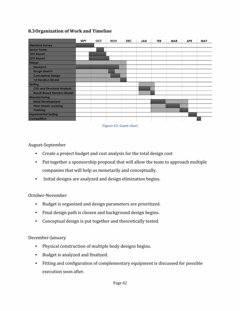
Page 62
8.3 Organization of Work and Timeline
Figure 63: Gantt chart
August-‐September
• Create a project budget and cost analysis for the total design cost
• Put together a sponsorship proposal that will allow the team to approach multiple
companies that will help us monetarily and conceptually.
• Initial designs are analyzed and design elimination begins.
October-‐November
• Budget is organized and design parameters are prioritized.
• Final design path is chosen and background design begins.
• Conceptual design is put together and theoretically tested.
December-‐January
• Physical construction of multiple body designs begins.
• Budget is analyzed and finalized.
• Fitting and configuration of complementary equipment is discussed for possible
execution soon after.

Page 63
February-‐March
• Final design is chosen and constructed.
• Testing, testing and more testing…
• Painting and cosmetic touches are added.
April-‐May
• Paperwork is put together and refined.
• Presentation and public speaking skills are reviewed in order to prepare for board
presentation.
• FSAE competition begins and the car is put to the test against other schools.
8.4 Breakdown of Responsibilities
In order to efficiently achieve the goals and milestones set, the breakdown of
responsibilities was done in such a way that relates to the strengths of each team member.
Javier Gutierrez will take responsibility of the designing stage, Angel Nuñez of the
manufacturing stage and Diego Quintero the analysis stage. Having this distribution as
such, it doesn’t mean that each team member will do that specific section on its entirety by
themselves, it means that the person will have the responsibility to act as a team leader for
that section and assign other members their required workload. That way it can be
assured that all team members gain the same knowledge and experience. The reports and
presentations will be done in conjunction.
Table 8: Breakdown of Responsibilities
Team Member Design Manufacture Analysis Reports Presentations
Javier Gutierrez Body, Side Pods * * *
Angel Nuñez * *
Diego Quintero Diffuser * * * *

Page 64
9. Conclusion
9.1 Conclusion and Discussion
In the previous figures it may be seen that the proposed body design has met and
surpassed the goals of this project in terms of safety, torsional rigidity, weight, and
coefficient of drag. For the researched material properties, a mass of 53.0 kg was found in
the proposed carbon fiber body design. Which, compared to the 30kg weight that was set at
the beginning of the past semester (fall 2012) is almost twice as much, meaning that a third
iteration analysis could be made in future papers using thinner thickness in the model.
Moreover, the same applies for the structural rigidity found of value 17,325 Nm/deg. that
compared with the value of the goal set of 3,000 Nm/deg. surpasses this value
tremendously. Also, the factor of safety found with this analyses is 94.7, confirming that a
thinner thickness can be used for the actual body. However, as some components and the
A-‐Spaced frame underneath the body of the vehicle were not included in these analyses the
true values for torsional rigidity (in this context referred to as “chassis loading” when loads
travel through the suspension) and coefficient of drag are not accurate to real world values.
The drag coefficient found for this design is 0.32 that compared to the goal value of 0.73 is
almost half, but by adding a spoiler to the vehicle this drag coefficient can be increased with
the purpose of generating more downforce.
9.2 Recommendations and future work
As stated above, a thinner thickness can be used for future models to decrease
overall weight and increase the performance of the vehicle. Also, other programs such as
Ansys can be used to further corroborate the results. Moreover, the values gained from the
FEA and CFD testing does not reflect errors, which may be made during manufacturing
which may compromise the strength of the structure. Real-‐world testing is necessary prior
to implementation of this design to ensure performance and more importantly, its safety.
One of the biggest gains of the completion of this project is the knowledge that future
FIU students will gain from our experience. Since this project was developed for the FIU

Page 65
SAE team, future members will be able to see our process, design considerations, and
further optimize our designs. At this point we can compare this year’s design, with the
previous year’s aerodynamics package and see the improvements. In the same fashion, we
can expect the same amount of improvement for future prototypes. The next step to
improve the current design is to further optimize the design by making it lighter while
gaining positive downforce. To accomplish this, the racecar prototype can be converted
into a hybrid-‐monocoque design, which would yield a lighter vehicle. Also, since the frame
of the car restricted most of the curves on the body, developing a sleeker and more efficient
frame design is critical for further performance enhancement. Other aspects to take into
consideration are the restrictions caused by the manufacturing process. During our
process, even though we took the manufacturing process into consideration, unforeseen
problems and new restrictions arose. One example of these new restrictions was the issues
caused when milling the molds with CNC machine. As each mold was milled, we noticed
that the machine had difficulties interpreting negative curvatures for each piece of the
body. After noticing these mistakes, the molds had to be manually repaired. Now that we
fully understand how the CNC machine operates, we can improve or design and mold
creation to avoid these errors.

Page 66
10. References
1) 21st, Sam // Oct, and 2012. "Racecar Engineering | The leading motorsport
technology magazine | F1, Le Mans, Formula Student, Super GT." Racecar
Engineering | The leading motorsport technology magazine | F1, Le Mans, Formula
Student, Super GT. N.p., n.d. Web. 28 Oct. 2012. <http://www.racecar-‐
engineering.com>.
2) "About | Panther Motorsports." Panther Motorsports | Florida International
University. N.p., n.d. Web. 17 Oct. 2012. <http://www.sae.fiu.edu/about-‐2>.
3) "autoevolution -‐ automotive news & test drives." autoevolution -‐ automotive news &
test drives. N.p., n.d. Web. 6 Nov. 2012. <http://www.autoevolution.com>.
4) Budynas, Richard G., J. Keith Nisbett, and Joseph Edward Shigley. Shigley's
mechanical engineering design. 9th ed. New York: McGraw-‐Hill, 2011. Print.
5) Clancy, L. J.. Aerodynamics. New York: Wiley, 1975. Print.
6) "Fiberglass , Epoxy , Composites, Carbon Fiber -‐ U.S. Composites, Inc.." Fiberglass ,
Epoxy , Composites, Carbon Fiber -‐ U.S. Composites, Inc.. N.p., n.d. Web. 1 Nov. 2012.
<http://www.uscomposites.com>.
7) "FSAE.com Forums." FSAE.com. N.p., n.d. Web. 15 Sep. 2012.
<http://www.fsae.com/groupee?s=763607348&cdra=Y>.
8) Hibbeler, Russell C.. Mechanics of materials. 8th ed. Boston: Prentice Hall, 2011.
Print.
9) "History." Global Formula Racing. N.p., n.d. Web. 5 Nov. 2012. <www.global-‐formula-‐
racing.com>.

Page 67
10) Milliken, William F., and Douglas L. Milliken. Race Car Vehicle Dynamics. Warrendale,
PA, U.S.A.: SAE International, 1995. Print.
11) "SAE Collegiate Design Series: Formula SAE®." Student Central. N.p., n.d. Web. 2 Oct.
2012. <http://students.sae.org/competitions/formulaseries/>.

Page 68
11. Appendices

Page 69
Appendix A. Technical Drawings

Page 70

Page 71
Figure 64: Ground Effects

Page 72

Page 73
Figure 65: Body – Left Wall Extension

Page 74

Page 75
Figure 66: Body – Left Wall

Page 76

Page 77
Figure 67: Body – Nose Bottom

Page 78

Page 79
Figure 68: Body – Nose LC

Page 80

Page 81
Figure 69: Body – Nose LL

Page 82

Page 83
Figure 70: Body – Nose RC

Page 84

Page 85
Figure 71: Body – Nose RR

Page 86

Page 87
Figure 72: Body – Rear Floor

Page 88

Page 89
Figure 73: Rear Hood

Page 90

Page 91
Figure 74: Body – Right Wall Extension

Page 92

Page 93
Figure 75: Body – Right Wall

Page 94

Page 95
Figure 76: Body – Sidepod Left -‐ Bottom
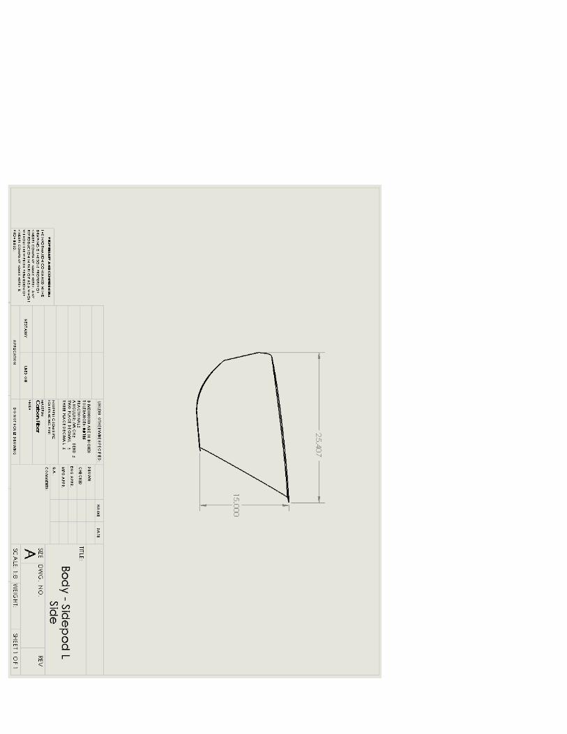
Page 96

Page 97
Figure 77: Body – Sidepod Left -‐ Side

Page 98

Page 99
Figure 78: Body – Sidepod Left -‐ Top

Page 100

Page 101
Figure 79: Body – Sidepod Right -‐ Bottom

Page 102

Page 103
Figure 80: Body – Sidepod Right -‐ Side

Page 104

Page 105
Figure 81: Body – Sidepod Right -‐ Top

Page 106
Appendix B. Formula SAE Body Rule Book

Page 107

Page 108

Page 109

Page 110

Page 111

Page 112

Page 113

Page 114

Page 115

Page 116

Page 117

Page 118

Page 119

Page 120

Page 121

Page 122

Page 123

Page 124
Appendix C. Quotes
Quote Date: 03/13/2013
Company: Fiberglass Coating Main Contact: Angel Nunez [email protected] (786) 953-0365 Secondary Contact(s): Javier Gutierrez Diego Quintero [email protected] [email protected] (786) 423-8148 (786) 877-5916
Table 9: Fiberglass Coating Quote
Item # Item Qty Unit Price Total 134505 1-‐1/2 -‐ 50 -‐ 1.28 lb x 99 1 $126.72 $126.72 125646 1708 -‐ 50 -‐ 1.83 lb x 100 1 $183.00 $183.00 133373 ISO Resin (gal.) 3 $26.00 $78.00 126150 Orange Tooling (gal.) 2 $44.00 $88.00 123984 MekP Catalyst (gal.) 1 $28.50 $28.50 130718 Carbon Fiber (yd.) 15 $30.00 $450.00 128848 Vinylester Polyester (gal.) 2 $36.00 $72.00 125979 Gel Coat (gal.) 1 $37.00 $37.00 128692 TR-‐104 Paste Wax 1 $12.50 $12.50 123942 TR-‐905 Mold Prep. Cleaner QT 1 $12.00 $12.00 123929 TR-‐301 Mold Sealer 1 $15.50 $15.50 129246 Box Chip Brushes 2" 2 $8.50 $17.00 129703 Laminating Roller 1/2" X 6" 3 $10.00 $30.00 133377 9" Naps 1 $5.99 $5.99 129209 4"Naps 1 $1.73 $1.73 129427 4" Frame 1 $1.10 $1.10 129429 9" Frame 1 $1.10 $1.10 129133 Acetone (gal.) 1 $15.99 $15.99 128903 L Gloves, Powdered (100ct) 1 $5.99 $5.99 129003 Respirator 6 $0.30 $1.80 129539 2" Tape 3 $3.64 $10.92 129957 Shears, 10" Trimmer 1 $35.00 $35.00
TOTAL: $1,229.84

Page 125
Appendix D. Apparatus
Figure 82: Techno CNC LC4896 Series