10000L-75000L Fuel Tank Operator's Manual
44
OPERATOR’S MANUAL FUEL TANKS 10,000L - 75,000L CAN/ULC-S601-14
Transcript of 10000L-75000L Fuel Tank Operator's Manual
OPERATOR’S MANUAL
FUEL TANKS10,000L - 75,000L
CAN/ULC-S601-14CERTIFIEDCSA W47.1

SIGN-OFF FORM
Meridian Manufacturing Inc. follows the general Safety Standards specified by the American Society of Agricultural Engineers (ASAE), and the Occupational Safety and Health Administration (OSHA). Anyone who will be using or maintaining the bin must read and clearly understand ALL Safety and Maintenance information presented in this manual.
Review this information annually, before the season start-up.
Make these periodic reviews of SAFETY and USAGE a standard practice for all of your equipment.
This form is provided for your record keeping to show that all personnel who will be working with the equipment have read and understand the information in this manual. Copy this page to continue record.
Date Employee’s Signature Employer’s Signature

Attention Dealers:You can register products online through the Dealer Login: http://dealers.meridianmfg.com/login/
It is mandatory to register your product in order to qualify for future warranty claims that may arise. Knowingly falsifying information on this form will result in the voiding of the product warranty.
You may scan/photograph this completed form (must be legible), email it to: [email protected] copy of this form may also be mailed to Meridian Manufacturing Inc.
Buyer’s Name ________________________________ Dealer’s Name ________________________________
Address ______________________________________ Address _____________________________________
City, Prov/State _______________________________ City, Prov/State _______________________________
Postal/Zip Code ______________________________ Postal/Zip Code ______________________________
Phone Number _______________________________ Phone Number _______________________________
Note: Registering a product in multiple entry format is only allowed when the product has the same model number and the same dealer, however each serial number must be legibly listed for each unit. Delivery dates for a multiple entry must be within a one month time frame.
Product Information _____________________________________________________________________________
Model Number ________________________________ Serial Number ________________________________
Invoice Date __________________________________
PRODUCT REGISTRATION FORM
Important: Please send this form to the Meridian Manufacturing Inc. location which built this product being registered. If you require further assistance call you’re dealer or the Meridian outlet nearest to your location.
We want to thank you for purchasing a Meridian manufactured product. Whether this is your first Meridian purchase or you have been a customer for years, you are now part of the Meridian community of customers and we appreciate your business.
It is important that you now complete the product registration information and this form indicating you have received delivery. This registration and information is necessary to ensure you have access to warranty and product updates in the event it be required in the future.
Registration can be completed by using this form or visiting your dealer who will complete the form online. You will be given access to the Meridian Community and become eligible for updates, special offers and prizes.
Again thank you for choosing Meridian.
I have thoroughly instructed the buyer on the above described equipment. The review included the content of this manual, equipment care, adjustments, safe operation and warranty policy.
Date _______________________ Dealer’s Signature __________________________________________________
The above equipment and this manual have been received by me. I have been thoroughly instructed as to care, adjustments, safe operation and applicable warranty policy.
Date _______________________ Buyer’s Signature ___________________________________________________

This page intentionally left blank

06.2021 i
Operator’s Manual: 10,000L - 75,000L Fuel Tanks
TABLE OF CONTENTS
DESCRIPTION PAGESection 1: INTRODUCTION . . . . . . . . . . . . . . . . . . . . . . . 1-1 1.1 Serial Number . . . . . . . . . . . . . . . . . . . . . . . . . . . . 1-1
Section 2: SAFETY. . . . . . . . . . . . . . . . . . . . . . . . . . . . . . 2-1 2.1 Safety Orientation . . . . . . . . . . . . . . . . . . . . . . . . . 2-2
2.2 General Safety . . . . . . . . . . . . . . . . . . . . . . . . . . . . 2-22.3 Equipment Safety Guidelines. . . . . . . . . . . . . . . . . 2-22.4 Environmental Regulations . . . . . . . . . . . . . . . . . . 2-32.5 Fuel Tank Safety. . . . . . . . . . . . . . . . . . . . . . . . . . . 2-32.6 Safety Decals . . . . . . . . . . . . . . . . . . . . . . . . . . . . . 2-3 2.6.1 Applying Decals . . . . . . . . . . . . . . . . . . . . . . . . 2-32.7 Safety Decal Location . . . . . . . . . . . . . . . . . . . . . . 2-42.8 Fuel Transfer Safety . . . . . . . . . . . . . . . . . . . . . . . . 2-5
Section 3: SITE AND INSTALLATION. . . . . . . . . . . . . . . . 3-1 3.1 Tank Base. . . . . . . . . . . . . . . . . . . . . . . . . . . . . . . . 3-2 3.2 Tank Installation . . . . . . . . . . . . . . . . . . . . . . . . . . . 3-2
Section 4: OPERATION . . . . . . . . . . . . . . . . . . . . . . . . . . 4-14.1 Tank Components . . . . . . . . . . . . . . . . . . . . . . . . . 4-24.2 Components and Controls. . . . . . . . . . . . . . . . . . . 4-34.3 Instructions for Spill Containment Device . . . . . . . 4-64.4 Top Fill Fuel Transfer . . . . . . . . . . . . . . . . . . . . . . . 4-74.5 Bottom Fill Fuel Transfer (Optional) . . . . . . . . . . . . 4-84.6 Measuring Fuel Level . . . . . . . . . . . . . . . . . . . . . . . 4-94.7 Pump Operation. . . . . . . . . . . . . . . . . . . . . . . . . . . 4-10
4.7.1 Dispensing Fuel . . . . . . . . . . . . . . . . . . . . . . . . 4-104.7.2 Locking the Pump . . . . . . . . . . . . . . . . . . . . . . 4-10
Section 5: SERVICE AND MAINTENANCE . . . . . . . . . . . 5-1 5.1 Tank Inspection . . . . . . . . . . . . . . . . . . . . . . . . . . . 5-1 5.1.1 Daily . . . . . . . . . . . . . . . . . . . . . . . . . . . . . . . . . 5-1 5.1.2 Annually . . . . . . . . . . . . . . . . . . . . . . . . . . . . . . 5-1 5.2 Fuel Meter Maintenance . . . . . . . . . . . . . . . . . . . . 5-2 5.2.1 Calibration . . . . . . . . . . . . . . . . . . . . . . . . . . . . 5-2 5.2.2 Maintenance. . . . . . . . . . . . . . . . . . . . . . . . . . . 5-2 5.2.3 Storage. . . . . . . . . . . . . . . . . . . . . . . . . . . . . . . 5-2
Section 6: TROUBLESHOOTING. . . . . . . . . . . . . . . . . . . 6-1
Section 7: REFERENCE. . . . . . . . . . . . . . . . . . . . . . . . . . 7-1 Dip Charts . . . . . . . . . . . . . . . . . . . . . . . . . . . . . . . . . . .7-1...Warranty Statement
ii 06.2021
Operator’s Manual: 10,000L - 75,000L Fuel Tanks
This page intentionally left blank
06.2021 1-1
Operator’s Manual: 10,000L - 75,000L Fuel Tanks
Section 1: INTRODUCTION
Thank you for choosing a Meridian® Fuel Tank.
Codes, Regulations and Guidelines:Designed and built to meet CAN/ULC-S601-14 standards for strength and durability. Your fuel tank will give years of environmentally safe, trouble free use. To ensure this performance, it is critical that everyone who will be working around or maintaining the tank, read and understand the Safety, Operation and Maintenance information within this manual.
Fuel storage tanks fall under a variety of governmental jurisdictions; therefore the references in this manual are provided only as a general outline. You may be subject to different legislation and governing bodies in your specific location.
IT IS THE TANK OWNER’S RESPONSIBILITY TO DETERMINE WHATCODES AND REGULATIONS MUST BE FOLLOWED IN YOUR LOCAL AREA
Meridian Manufacturing Inc. assumes no responsibility for any errors that may appear in this manual and shall not be liable under any circumstances for incidental, consequential or punitive damages in connection with, or arising from, the use of this manual.
Information provided herein is of a descriptive nature. Meridian Manufacturing Inc. reserve the right to modify the equipment design and specifications without any preliminary notice.
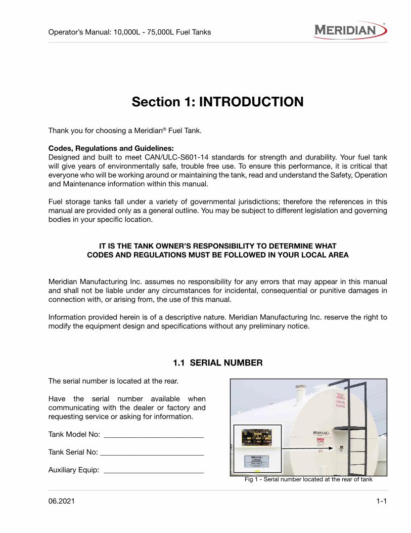
1.1 SERIAL NUMBER
The serial number is located at the rear.
Have the serial number available when communicating with the dealer or factory and requesting service or asking for information.
Tank Model No: ___________________________
Tank Serial No: ____________________________
Auxiliary Equip: ___________________________Fig 1 - Serial number located at the rear of tank
1-2 06.2021
Operator’s Manual: 10,000L - 75,000L Fuel Tanks
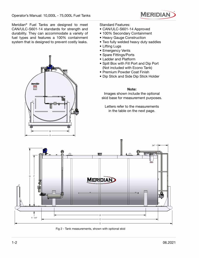
Meridian® Fuel Tanks are designed to meet CAN/ULC-S601-14 standards for strength and durability. They can accommodate a variety of fuel types and features a 100% containment system that is designed to prevent costly leaks.
Standard Features:• CAN/ULC-S601-14 Approved• 100% Secondary Containment• Heavy Gauge Construction• Two fully welded heavy duty saddles• Lifting Lugs• Emergency Vents• Spare Fittings/Ports• Ladder and Platform• Spill Box with Fill Port and Dip Port
(Not included with Econo Tank)• Premium Powder Coat Finish• Dip Stick and Side Dip Stick Holder
Note:Images shown include the optional
skid base for measurement purposes.
Letters refer to the measurementsin the table on the next page.
Fig 2 - Tank measurements, shown with optional skid
G F
1'- 1/4"
E
C
DB
A
24"
G F
1'- 1/4"
E
C
DB
A
24"

06.2021 1-3
Operator’s Manual: 10,000L - 75,000L Fuel Tanks
Tabl
e 1
- Ta
nk W
eigh
ts
MO
DE
LIT
EM
#V
OLU
ME
TAN
K W
EIG
HT
(E
MP
TY
)S
KID
WE
IGH
TW
EIG
HT
W/S
KID
BO
TT
OM
FIL
L W
EIG
HT
MD
W-1
0000
6410
010
600
L (2
332
Imp
G)
1627
kg
(358
8 lb
)39
6 kg
(87
2 lb
)20
23 k
g (4
460
lb)
--
MD
WE
-150
0064
088
1500
0 L
(330
0 Im
p G
)27
27 k
g (6
011
lb)
----
129
kg (
284
lb)
MD
WE
-250
0064
089
2500
0 L
(549
9 Im
p G
)N
/A--
--12
9 kg
(28
4 lb
)
MD
WE
-350
0064
090
3500
0 L
(769
9 Im
p G
)N
/A--
--12
9 kg
(28
4 lb
)
MD
W-1
5000
6400
314
800
L (3
256
Imp
G)
2590
kg
(571
0 lb
)92
2 kg
(20
32 lb
)35
12 k
g (7
743
lb)
129
kg (
284
lb)
MD
W-2
5000
6401
024
900
L (5
477
Imp
G)
3613
kg
(796
5 lb
)11
04 k
g (2
435
lb)
2140
kg
(471
7 lb
)12
9 kg
(28
4 lb
)
MD
W-3
5000
6403
535
000
L (7
699
Imp
G)
4713
kg
(103
90 lb
)12
84 k
g (2
831
lb)
5997
kg
(132
21 lb
)12
9 kg
(28
4 lb
)
MD
W-5
0000
6405
050
000
L (1
0998
Imp
G)
6804
kg
(150
00 lb
)16
55 k
g (3
649
lb)
8459
kg
(186
49 lb
)13
8 kg
(30
4 lb
)
MD
W-6
5000
6141
365
100
L (1
4320
Imp
G)
8301
kg
(183
00 lb
)18
90 k
g (4
167
lb)
1019
1 kg
(22
467
lb)
138
kg (
304
lb)
MD
W-7
5000
6407
675
800
L (1
6674
Imp
G)
9226
kg
(203
40 lb
)29
83 k
g (4
576
lb)
1220
9 kg
(26
916
lb)
138
kg (
304
lb)
Tabl
e 2
- Ta
nk M
easu
rem
ents
MO
DE
LIT
EM
#TA
NK
DIA
ME
TE
R(A
)
INT
ER
NA
L D
IME
NS
ION
(ID X
LE
NG
TH
)S
KID
WID
TH
(B)
TAN
K L
EN
GT
H(C
)
LEN
GT
H B
ET
WE
EN
S
AD
DLE
S(D
)
LEN
GT
Hw
/ E
XT-
SK
ID(E
)
TAN
K O
VE
RA
LLH
EIG
HT
(F)
PU
MP
OV
ER
ALL
HE
IGH
T(G
)
MD
W-1
0000
6410
064
”63
” ID
x 2
09”
4’ 9
”17
’ 5”
14’ 1
1”23
’ 9”
5’ 8
”7’
2”
MD
WE
-150
0064
088
90”
N/A
5’ 4
”12
’ 4”
----
8’9’
7”
MD
WE
-250
0064
089
90”
N/A
5’ 4
”20
’ 7”
----
8’9’
7”
MD
WE
-350
0064
090
90”
N/A
5’ 4
”29
’ 1”
----
8’9’
7”
MD
W-1
5000
6400
390
”89
” ID
x 1
47”
6’ 6
”12
’ 4”
8’ 7
”19
’ 7”
7’ 9
”9’
1”
MD
W-2
5000
6401
090
”89
” ID
x 2
47”
6’ 6
”20
’ 8”
16’ 1
1”27
’ 11”
7’ 9
”9’
1”
MD
W-3
5000
6403
590
”89
” ID
x 3
49”
6’ 6
”29
’ 2”
25’ 5
”36
’ 1”
7’ 9
”9’
1”
MD
W-5
0000
6405
012
0”11
8” ID
x 2
79”
7’ 7
”23
’ 4”
18’ 4
”31
’ 6”
10’ 3
”11
’ 7”
MD
W-6
5000
6141
312
0”11
8” ID
x 3
63”
7’ 7
”30
’ 4”
25’ 4
”38
’ 6”
10’ 3
”11
’ 7”
MD
W-7
5000
6407
612
0”11
8” ID
x 4
23”
7’ 7
”35
’ 4”
30’ 4
”43
’ 6”
10’ 3
”11
’ 7”
Ski
d be
d is
1’ 1
/4”
thic
k •
Rea
r La
dder
is 2
4” w
ide
• R
ear
Sta
ircas
e is
29”
wid
e

1-4 06.2021
Operator’s Manual: 10,000L - 75,000L Fuel Tanks
This page intentionally left blank

06.2021 2-1
Operator’s Manual: 10,000L - 75,000L Fuel Tanks
Section 2: SAFETY
The Safety Alert Symbol means:
ATTENTION!BECOME ALERT!
YOUR SAFETY IS INVOLVED! The Safety Alert Symbol identifies important safety messages on the fuel tank and in this manual.
3 Big Reasons why safetyis important to you:
• Accidents Disable and Kill• Accidents Cost• Accidents Can Be Avoided
The following signal words are used in this manual to expressthe degree of hazard for areas of personal safety.
When you see the symbol and/or the signal words described below,obey the accompanying message to avoid possible injury or death.
Indicates a hazardous situation that, if not avoided, will result in death or serious injury. This signal word is limited to the most extreme situations. Typically for machine components which, for functional purposes, cannot be guarded.
Indicates a hazardous situation, if not avoided, could result in death or serious injury. This word identifies hazards that are exposed when guards are removed. It may be used to alert against unsafe practices.
Indicates a hazardous situation, if not avoided, could result in minor or moderate injury. It may be used to alert against unsafe practices.
Indicates practices or situations which may result in the malfunction of, or damage to equipment.
Safety instructions (or equivalent) signs indicate specific safety-related instructions or procedures.

2-2 06.2021
Operator’s Manual: 10,000L - 75,000L Fuel Tanks
2.1 SAFETY ORIENTATION
YOU are responsible for the SAFE usage and maintenance of your Meridian® Fuel Tank. Be sure that everyone who will maintain or work around it, is familiar with the safety, maintenance procedures.
This manual will take you step-by-step through your working day. It will alert you to all the safe practices that should be adhered to while using the tank.
It has been said, “The best safety feature is an informed, careful worker” Good safety practices not only protect you but also the people around you. Make these practices a dynamic part of your workday.
Most accidents can be prevented. Do not risk injury or death by ignoring good safety practices.
• Fuel tank owners must give instructions toemployees before allowing them to use thetank.
Procedures must be reviewed annuallythereafter, as per OSHA (Occupational Safetyand Health Administration) regulation 1928.57.
• Develop a comprehensive safety program foryour work area.
• The most important safety device is a SAFEworker. It is their responsibility to understandall safety and usage instructions in thisdocument, and to follow them.
• An untrained worker exposes himself andbystanders to possible serious injury or death.
• Think SAFETY! Work SAFELY!
2.2 GENERAL SAFETY
• You are responsible for the safe useand maintenance of this tank. Goodsafety practices not only protectyou, but also those around you. Allaccidents can be avoided.
• Provide a fire extinguisher for usein case of an accident. Store in ahighly visible place.
• Use this fuel tank for its intended purpose only.
• This tank is not intended for use by children.
2.3 EQUIPMENT SAFETY GUIDELINES
• Safety of the workers and bystanders is oneof the main concerns when designing anddeveloping this fuel tank. However, every yearmany accidents occur which could have beenavoided by a few seconds of thought, and amore careful approach to handling equipment.
• DO NOT allow personnel to use this tankuntil they have read this manual. They shouldhave a thorough understanding of the safetyprecautions.
Review the safety instructions with all usersannually.
• DO NOT modify the tank in any way withoutwritten permission from the manufacturer. Anyunauthorized modification of the fuel tank willvoid the warranty.

06.2021 2-3
Operator’s Manual: 10,000L - 75,000L Fuel Tanks
2.4 ENVIRONMENTAL REGULATIONS
• The fuel tank installer shall ensure that all environmental requirements are taken and implemented in accordance with the local authority having jurisdiction.
• This tank must be installed by a qualified tank installer who shall consult with the proper authorities with jurisdiction to ensure all requirements of CAN/ULC-S601-14 and all Federal, Provincial and Local codes are being met prior to installation. Failure to do so, could void your warranty.
• Protect Fuel Tank Against Vehicle Traffic:The installer is to ensure that the fuel tank is adequately protected against damage from vehicular traffic in compliance with all Federal, Provincial and Local Codes.
• Regular Inspection and Maintenance:The fuel tank is to be inspected annually and any repairs to the exterior coating shall be made at the time of inspection in accordance with the coating manufacturer’s instructions.
2.5 FUEL TANK SAFETY
• Do not lift or transport the tank when it contains fluid.
• Install the tank away from buildings, property lines, public paths or high traffic areas.
• Protect the tank against damage from vehicular traffic in compliance with all Federal, Provincial and Local Codes.
• Install the tank on a well prepared, level base designed to hold the tank full of liquid.
2.6 SAFETY DECALS
• Keep safety decals clean/legible at all times.
• Replace safety decals that are missing or have become illegible.
• All safety decals have a part number in the lower right hand corner. Use this part number when ordering replacements.
• Safety decals are available from your authorized distributor, dealer’s parts department or from the factory.
2.6.1 Applying Decals:1. Be sure the application area is clean and
dry. Ensure the surrounding temperature is above 10°C (50°F).a. Remove all dirt, grease, wax from surface.b. Clean with a non-ammonia based
cleaner.c. Wipe the clean surface with isopropyl
alcohol on paper towel, and allow to dry.
2. Determine the exact position before you remove the backing paper.
3. Peel a small portion of the split backing paper.
4. Align the decal over the specified area. Use a squeegee to carefully press the small portion, with the exposed adhesive backing, into place.
5. Slowly peel back the remaining paper and carefully smooth the rest of the decal into place.
6. Small air pockets can be pierced with a pin and smoothed out using the squeegee, or a piece of sign backing paper.

2-4 06.2021
Operator’s Manual: 10,000L - 75,000L Fuel Tanks
2.7 SAFETY DECAL LOCATION
1. ULC Plate (part #20027)Located on rear of tank
2. Serial Number DecalLocated below ULC Plate
3. Emergency Venting Decal (part #20105)Located below emergency vents
4. Containment Inspection Warning Decal (part #20045)Located below containment inspection port
5. Lifting Lug Warning Decal (part #19037)Located below lifting lug
6. Vent Warning Decal (part #20026)Located below 3” port
8. Danger Safety Decal (part #20048)Located on both ends of tank
9. Consult Authority Decal (part #20046)Located on front, below safety decal
7. Fill Warning Decal (part #20022)Located below vented fill cap
Fig 3 - Rear of fuel tank
Fig 4 - Fuel tank decal location
The following illustrations show the general location of safety decals on fuel tanks. The position of decals may vary depending on the tank’s options. Decals are not shown at actual size.
10. Warning Falling Hazard Decal (part #19961)Located next to ladder
G F
1'- 1/4"
E
C
DB
A
24"
4 7 9
8 10
1 2
G F
1'- 1/4"
E
C
DB
A
24"
57
36
53
8

06.2021 2-5
Operator’s Manual: 10,000L - 75,000L Fuel Tanks
2.8 FUEL TRANSFER SAFETY
• Procedures must be in place when transferring fuel from a delivery vehicle to the tank. Although some transfer procedures are unique to those facilities, the following general safety procedures must always be followed: - DO NOT smoke when operating or refueling the fuel tank.
- Keep sparks, flames & hot material away from the fuel tank.
- Turn vehicle ignition off and remove key from ignition before refueling.
- Keep vehicles at least 1.5 m (5’) away from the fuel tank at all times.
- Never leave the tank unattended while refueling is in process.
- DO NOT overfill. 95% capacity is the maximum legal limit.
- Always turn pump off when finished fueling operations.
- Always store pump nozzle in drip pot when not in operation.
• ALWAYS determine how much fuel your tank can safely hold. Over-filling the tank will cause spills. - Check the fuel level by dip checking the tank prior to any fuel transfer.
• Determine a Safe Gauge Height (SGH) this is how much fuel a tank can hold allowing for expansion due to temperature variations. - 90% full in the summer months - 95% full in the winter months
• ALWAYS start the fuel transfer at a reduced rate. This reduces the potential for the build up of static electricity.
• ALWAYS maintain good communication with the driver of the delivery vehicle. Poor communication between the tank operator and the delivery driver often leads to spills and accidents.

2-6 06.2021
Operator’s Manual: 10,000L - 75,000L Fuel Tanks
This page intentionally left blank

06.2021 3-1
Operator’s Manual: 10,000L - 75,000L Fuel Tanks
Page 10www.meridianmfg.com
2300L & 4600L DW Fuel Tanks Fuel Transfer
Installing The TankThis document only covers general installation instructions. Consult the correct authority having jurisdiction in your area prior to tank installation.
NOTE: This tank must be installed by a qualified tank installer who shall consult with the proper authorities with jurisdiction to ensure all requirements of CAN/ULC-S601-07 and all Federal, Provincial and Local codes are being met prior to installation. Failure to do so, could void your warranty.
InstallationAll timber/crates used in shipping must be completely removed from the tank prior to installation of tank.
Choosing a Location The tank shall be placed at a safe distance from buildings, other tanks, roadways, waterways, property lines and all public paths (1). Refer to local authorities for applicable codes.
Installing the Fuel Tank BaseThe tank shall be installed on a level base (2) designed to support the tank weight plus 100% liquid loading. The tank skid, saddle or cradle shall be the only part of the tank in contact with the foundation or base.
1
2
This document only covers general installation instructions. Consult the correct authority having jurisdiction in your area prior to tank installation.
IMPORTANT:This tank must be installed by a qualified tank installer who shall consult with the proper authorities with jurisdiction to ensure all requirements of CAN/ULC-S601-14 and all Federal, Provincial and Local codes are being met prior to installation. Failure to do so, could void your warranty.
Note:All timber/crates used in shipping must be completely removed from the tank prior to installation.
Choosing a Location:The tank shall be placed at a safe distance from buildings, other tanks, roadways, waterways, property lines and all public paths. Refer to local authorities for applicable codes.
Fig 5 - Tank location
Section 3: SITE AND INSTALLATION
• Read and understand the Operator’s Manual, and all safety decals, before using.
• Never lift or attempt to transport tankscontaining fluid.
• Inspected the fuel tank annually.
• Ensure that all environmental requirementsare taken and implemented in accordancewith the local authority having jurisdiction.
• Ensure that the fuel tank is adequatelyprotected against damage from vehiculartraffic in compliance with all Federal,Provincial and Local Codes.

3-2 06.2021
Operator’s Manual: 10,000L - 75,000L Fuel Tanks
3.1 TANK FOUNDATION
The foundation specifications will depend on your local soil conditions.
Meridian Manufacturing Inc. will not assume any liability for results arising from a poorly prepared foundation.
Meridian strongly advises you to consult a civil engineer regarding the site you choose. A professional engineer will check the soil conditions and soil load bearing capacity. They can use the tank’s empty and full weights to advise on preparing the proper base.
The site should be in a well-drained location with all silt, organic, and loose soil removed. Topsoil should be excavated, and a gravel foundation be laid.
The gravel foundation should be FIRMLY PACKED, uniform, level and extend beyond the perimeter of the tank. It should not vary by more than 1/4” over a span of four feet. It must be capable of carrying 100% of the weight of the full tank.
The tank skid, saddle or cradle shall be the only part of the tank in contact with the foundation or base.
3.2 TANK INSTALLATION
Lifting and Transporting Fuel Tanks:Only the lifting lug weldments on the tank shall be used for unloading or transporting the empty fuel tank. DO NOT lift or transport tanks containing fluid at any time.
Inspecting Fuel Tanks:The tank installer shall ensure that all fittings, have not loosened during transportation. They must be sealed and tight.
Check all painted areas of the tank for damage due to shipping and also at final installation. All scratched or scuffed areas must be touched up with paint prior to use. If the damages are deemed to affect the integrity of the tank, contact your distributor or dealer prior to putting any product in the tank.
Tank Venting:The emergency vents are installed by Meridian. The normal vent is to be field-installed by a qualified tank installer prior to use of the tank to prevent pressure or vacuum inside the tank during filling, emptying, or atmospheric temperature changes that may occur.
Containment Inspection:The containment tank should be checked on a regular basis, to confirm that neither precipitation nor product has accumulated therein. The disposal of any liquid found in the containment shall be disposed of in accordance with the requirements of the authority having jurisdiction.

06.2021 3-3
Operator’s Manual: 10,000L - 75,000L Fuel Tanks
Inspecting Fuel Tank Containment System:The containment should be checked on a regular basis, to confirm that neither product nor water has accumulated therein. Take immediate remedial action if product or water is found. The disposal of any liquid found in the containment shall be disposed of in accordance with the requirements of the authority having jurisdiction.
Environmental Regulations:The fuel tank installer shall ensure that all environmental requirements are taken and implemented in accordance with the local authority having jurisdiction.
Protect Fuel Tank Against Vehicle Traffic:The installer is to ensure that the fuel tank is adequately protected against damage from vehicular traffic in compliance with all Federal, Provincial and Local Codes.
CORROSION HAZARDMicrobial corrosion can be caused bywater & debris getting into the tank.
Regular Inspection and Maintenance:The fuel tank must be inspected regularly. All repairs to the exterior coating shall be made at the time of inspection in accordance with the coating manufacturer’s instructions.
Refer to the Petroleum Equipment Institute (PEI) website or Steel Tank Institute for more information on removing water and debris, and preventing corrosion inside the tank.
Overfill Protection:The tank installer must ensure that an approved OVERFILL PROTECTION DEVICE is installed in the tank prior to the tank being filled with any fuel.
Fuel Level Inspection Port:This port is located in the 25” Spill Box on top of the tank. The 2” lockable port allows the tank to be probed with the dip stick located on the side of the tank in order that the remaining level of fuel is established (refer to the tank depth chart in the owner’s manual) before the refueling of the tank begins.
Spill Box Connection:Ensure the hose is properly secured to the 3” connection inside the Spill Box before refueling begins. Never leave while refueling the tank. After the refueling process is completed, drain the hose before disconnecting to eliminate any spilling of fluid. Attach the fill cap and close the Spill Box lid.
Bottom Fill System (Optional):The 3” bottom fill system has a one way valve installed at the factory to prevent fuel from flowing back down the fill line. Ensure the one-way valve has not been tampered with and is installed correctly (arrow pointing up). Secure the fill hose to the three inch bottom fill connection and then open the ball valve on the bottom fill before beginning the refueling process. Never leave while the refueling of the tank is in process. After refueling is complete drain the hose to eliminate any chance of spilled fuel. Close the ball valve, remove the hose and replace the fill cap on the bottom fill.

3-4 06.2021
Operator’s Manual: 10,000L - 75,000L Fuel Tanks
This page intentionally left blank
06.2021 4-1
Operator’s Manual: 10,000L - 75,000L Fuel Tanks
Section 4: OPERATION
• Read and understand the Operator’s Manual, and all safety decals, before using.
• DO NOT smoke when operating/refuelingthe fuel tank.
• Keep sparks, flames & hot material awayfrom the fuel tank.
• Be sure tank skid is properly secured so itcannot shift or move when the tank is emptyor full.
• Turn vehicle ignition off and remove key fromignition before refueling.
• Keep vehicles at least 1.5 m (5’) away fromthe fuel tank at all times.
• NEVER leave the tank unattended whilerefueling is in process.
• ALWAYS turn pump off when finished fueling.
• DO NOT OVERFILL. 95% capacity is themaximum legal limit.
• ALWAYS store pump nozzle in drip pot whennot in operation.
• ALWAYS determine how much fuel yourtank can safely hold. Over filling the tankwill cause spills. Check the fuel level by dipchecking the tank prior to any fuel transfer.
• ALWAYS start the fuel transfer at a reducedrate. This reduces the potential for the buildup of static electricity.
• ALWAYS maintain good communication withthe driver of the delivery vehicle.
Hazard controls and accident prevention are dependent upon the personnel operating and maintaining the equipment. Their awareness, concern, prudence and proper training are crucial.
It is the responsibility of the owner and operators to read this manual and to train all personnel before they start working with this tank. By following recommended procedure, a safe working environment is provided for the operator, co-workers and bystanders in the area around the work site.

4-2 06.2021
Operator’s Manual: 10,000L - 75,000L Fuel Tanks
2” CONTAINMENT TANK INSPECTION PORT
6” OR 8” EMERGENCY VENT (CONTAINMENT)
LADDER AND PLATFORM
6” PORT,OPTIONAL REAR-MOUNT BOTTOM FILL SYSTEM
LIFT LUG
3” PORT,3” VENT INCLUDED W/ PUMP PACKAGE
6” OR 8” EMERGENCY VENT(PRIMARY)
LIFT LUG
2” PORT
4” PORT
2” PORT,MECO AUDIBLE ALARM
4” DISPENSING PORT,OPTIONAL FUEL PUMP PACKAGE
ON/OFF SWITCH
OPTIONAL HOSE PACKAGE
DIP STICK
25” SPILL BOX:- 3” MALE CAM LOCK FILL PORT- 2” DIP PORT
6” PORT,OPTIONAL FRONT-MOUNTBOTTOM FILL SYSTEM
2” CONTAINMENT TANKINSPECTION PORT
6” OR 8” EMERGENCY VENT (CONTAINMENT)
LADDERAND
PLATFORM
2-1/2” DIP PORT
LIFT LUG
3” PORT,2” VENT INCLUDED W/ PUMP PACKAGE
6” OR 8” EMERGENCY VENT (PRIMARY)
LIFT LUG
2” PORT
2” PORT,MECO OVERFILL ALARM
6” PORT,FRONT-MOUNT BOTTOM FILL SYSTEM
4” DISPENSING PORT,OPTIONAL FUEL PUMP PACKAGE
HOSE RETRACTOR W/ POST
INTEGRATED TANK SKID
DIP STICK
6” D-RING(ONE AT EACH
CORNER)
OPTIONAL HOSE PACKAGE
4.1 TANK COMPONENTS
Port and vent sizes may vary. Component positions may change, depending on tank size and included options.
Fig 6 - Standard Fuel Tank components,25,000 Litre Standard Tank shown
Fig 7 - Econo Fuel Tank components,25,000 Litre Econo Fuel Tank
NOTE:If Rear-Mount Bottom Fill is included,
No Cam Lock is in Spill Box.

06.2021 4-3
Operator’s Manual: 10,000L - 75,000L Fuel Tanks
4.2 COMPONENTS AND CONTROLS
Before working with this tank, all operators must familiarize themselves with the location and function of the components and controls.
Locations of components and options may vary.
Liquid Level Gauge:This gauge give a general reading of the amount of fuel in the tank.
IMPORTANT:Do not depend on Level Gauge when
filling the tank. Use dipstick and dip chart.Always dip and measure level
before and after filling the tank.
Spill Box:Inside the 25” Spill Box is the 3” Fill port, covered by a male cam lock, and 2” Dip port.Note: If tank is equipped with a Rear-Mount Bottom Fill isystem, there will be no Cam Lock in the Spill Box.
2” Containment Tank Inspection Port:The Inspection Port is on the end of the tank beside the Spill Box. See Figure 9.• An optional Leak Detection Gauge can be
added to the port.
Emergency Vents:• The primary emergency vent is located at the
centre of the tank. See Figure 10.• A secondary containment vent is positioned
along on the side, at the rear of the tank.
Fig 8 - Liquid level gauge
Fig 9 - Containment Inspection Port w/ Leak Detection Gauge
Fig 10 - Primary emergency vent
Fig 11 - Secondary containment emergency vent
4-4 06.2021
Operator’s Manual: 10,000L - 75,000L Fuel Tanks
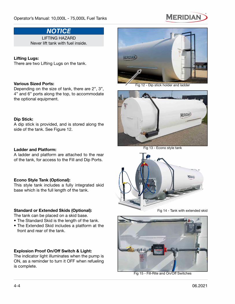
LIFTING HAZARDNever lift tank with fuel inside.
Lifting Lugs:There are two Lifting Lugs on the tank.
Various Sized Ports:Depending on the size of tank, there are 2”, 3”, 4” and 6” ports along the top, to accommodate the optional equipment.
Dip Stick:A dip stick is provided, and is stored along the side of the tank. See Figure 12.
Ladder and Platform:A ladder and platform are attached to the rear of the tank, for access to the Fill and Dip Ports.
Econo Style Tank (Optional):This style tank includes a fully integrated skid base which is the full length of the tank.
Standard or Extended Skids (Optional):The tank can be placed on a skid base.• The Standard Skid is the length of the tank.• The Extended Skid includes a platform at the
front and rear of the tank.
Explosion Proof On/Off Switch & Light:The indicator light illuminates when the pump is ON, as a reminder to turn it OFF when refueling is complete.
Fig 12 - Dip stick holder and ladder
Fig 13 - Econo style tank
Fig 15 - Fill-Rite and On/Off Switches
Fig 14 - Tank with extended skid
06.2021 4-5
Operator’s Manual: 10,000L - 75,000L Fuel Tanks
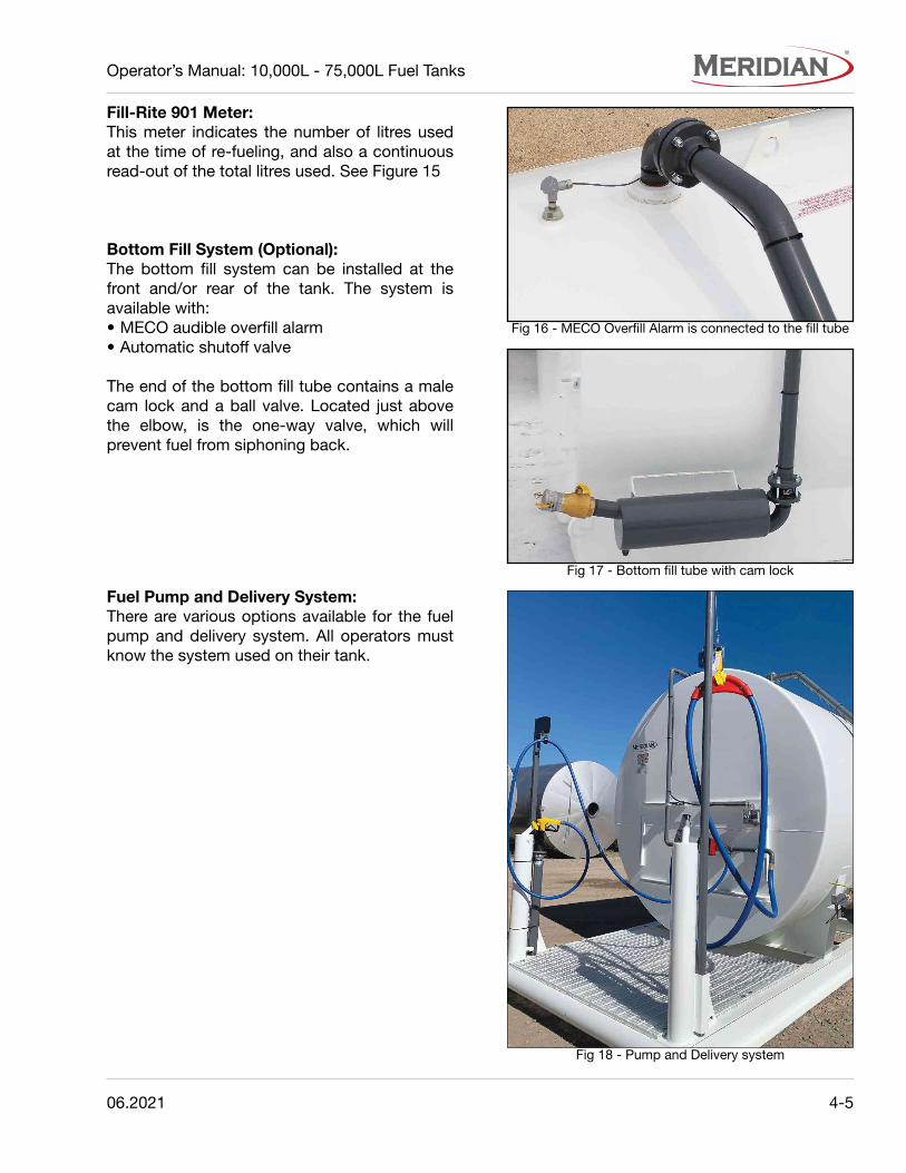
Fill-Rite 901 Meter:This meter indicates the number of litres used at the time of re-fueling, and also a continuous read-out of the total litres used. See Figure 15
Bottom Fill System (Optional):The bottom fill system can be installed at the front and/or rear of the tank. The system is available with:• MECO audible overfill alarm• Automatic shutoff valve
The end of the bottom fill tube contains a male cam lock and a ball valve. Located just above the elbow, is the one-way valve, which will prevent fuel from siphoning back.
Fuel Pump and Delivery System:There are various options available for the fuel pump and delivery system. All operators must know the system used on their tank.
Fig 16 - MECO Overfill Alarm is connected to the fill tube
Fig 17 - Bottom fill tube with cam lock
Fig 18 - Pump and Delivery system

4-6 06.2021
Operator’s Manual: 10,000L - 75,000L Fuel Tanks
4.3 INSTRUCTIONS FOR FUEL DELIVERY PERSONNEL
IMPORTANT:All 15 - 75,000 Litre tanks sold in Manitoba and Ontario must have an Overfill Shutoff Valve installed (Part #70021) prior to be put in service and filled with fuel.
1. The fuel delivery personnel shall ensure thatall applicable Federal, Provincial and LocalCodes are met during the filling of the tank.
2. The fuel delivery personnel shall be familiarwith, and trained on, proper above groundtank filling procedures.
3. The fuel delivery personnel responsible fortransferring product to an above ground tankshall take all reasonable steps to preventspillage.
4. The fuel delivery personnel shall remain inconstant view of the transfer nozzle and fillpipe and shall be in constant attendance atthe discharge control valve when the tank isbeing filled.

06.2021 4-7
Operator’s Manual: 10,000L - 75,000L Fuel Tanks
DO NOT dispense fuel whentransfer is in process
1. Have a pre-transfer meeting with the deliveryvehicle operator, to determine the correctproduct is being transferred into the correcttank.
2. Inspect the tank and transfer hose:- Check that the vents are unobstructed.- Check the transfer hose for leaks, cracks
or damage. If leaks are present or laterappear, stop transfer, repair as necessary.
3. Lift the Spill Box Cover to expose the 3”male Cam Lock Fill Port and 2” Dip Port.
4. Clean the area before refueling begins.
5. Check the fuel level, through the dip port, todetermine the quantity needed.
6. Remove the cotter pins from each side of the3” Cam Lock that secures the Fill Cap.- Lower the retraining latches and pull off
the Fill Cap.
7. Attach the transfer hose around the 3” maleCam Lock and hand tighten the connection.
Note:If the delivery vehicle does not have a matching 3” female Cam Lock, then fill with a nozzle through the 3” fill port.
8. Start delivery vehicle pump and slowly beginfuel transfer.- Use the Dip Port to monitor and measure
the filling process.- Only increase the flow of the product when
you are sure there are no problems.
9. DO NOT WALK AWAY DURING TRANSFER.- Continuously monitor the transfer of fuel.- At all times, keep open communication
between delivery vehicle and tank operator.- DO NOT OVERFILL.
Guidelines:In summer, fill tank no more than 90% full.In winter, fill tank no more than 95% full.
10. Reduce fuel transfer rates when nearing thetop of the tank to avoid overfilling the tanks.- Notify the delivery vehicle operator when
the transfer procedure is almost complete.
11. Turn off the delivery vehicle delivery pump.
12. Remove delivery hose.- Secure the hose back on the delivery
vehicle.
13. Dip tank and record amount of fuel delivered.
14. Close the fill lid and the Dip Port lid.- Lock the 3” Cam Lock.- Secure with the cotter pins.
15. Close and secure the Spill Box cover.
Fig 19 - Inside the Spill Box on standard tank
4.4 TOP FILL FUEL TRANSFER
4-8 06.2021
Operator’s Manual: 10,000L - 75,000L Fuel Tanks
DO NOT dispense fuel whentransfer is in process
There are three options for bottom fill systems:• Front-side mount• Rear mount• Dual bottom fill (for multiple compartment
tanks)
Fuel is pumped, under pressure from the delivery vehicle, using the 3” Cam Lock located at the base of the tank, in through the top.
1. Have a pre-transfer meeting with the deliveryvehicle operator, to determine the correctproduct is being transferred into the correcttank.
2. Inspect the tank and transfer hose:- Check that the vents are unobstructed.- Check the transfer hose for leaks, cracks
or damage. If leaks are present or laterappear, stop transfer, repair as necessary.
3. Check the fuel level to determine the quantityneeded.- Use the 2” Dip Port inside the Spill Box.
4. Turn the fill ball valve to the “OFF” position.
5. Wipe the area around the 3” Cam Lock toprevent fuel contamination.
6. Remove the cotter pins from each side of the3” Cam Lock that secures the Fill Cap.- Rotate the retraining latches and pull off
the Fill Cap.
7. Attach the transfer hose around the 3” maleCam Lock and hand tighten the connection.
8. Turn the fill ball valve to the “ON” position.
9. Start delivery vehicle pump and slowly beginfuel transfer.- Use the Dip Port to monitor and measure
the filling process.- Only increase the flow of the product when
you are sure there are no problems.
10. DO NOT WALK AWAY DURING TRANSFER.- Continuously monitor the transfer of fuel.- At all times, keep open communication
between delivery vehicle and tank operator.- DO NOT OVERFILL.
Guidelines:In summer, fill tank no more than 90% full.In winter, fill tank no more than 95% full.
11. Reduce fuel transfer rates when nearing thetop of the tank to avoid overfilling the tanks.- Notify the delivery vehicle operator when
the transfer procedure is almost complete.
12. Turn off the delivery vehicle delivery pump.
13. Turn the fill ball valve to the “OFF” position.
14. Remove delivery hose.- Secure the hose back on the delivery
vehicle.
15. Dip tank and record amount of fuel delivered.
16. Close the fill lid.- Lock the 3” Cam Lock.- Secure with the cotter pins.
17. Close the Dip Port lid.- Secure the Spill Box cover.
4.5 BOTTOM FILL FUEL TRANSFER (OPTIONAL)
06.2021 4-9
Operator’s Manual: 10,000L - 75,000L Fuel Tanks
4.6 MEASURING FUEL LEVEL
Never smoke around the fuel tank orexpose the tank to direct flame.
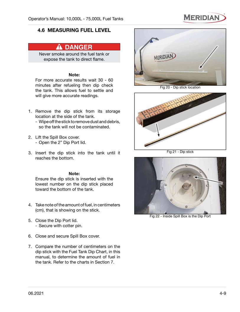
Note:For more accurate results wait 30 - 60 minutes after refueling then dip check the tank. This allows fuel to settle and will give more accurate readings.
1. Remove the dip stick from its storagelocation at the side of the tank.- Wipe off the stick to remove dust and debris,
so the tank will not be contaminated.
2. Lift the Spill Box cover.- Open the 2” Dip Port lid.
3. Insert the dip stick into the tank until itreaches the bottom.
Note:Ensure the dip stick is inserted with the lowest number on the dip stick placed toward the bottom of the tank.
4. Take note of the amount of fuel, in centimeters (cm), that is showing on the stick.
5. Close the Dip Port lid.- Secure with cotter pin.
6. Close and secure Spill Box cover.
7. Compare the number of centimeters on thedip stick with the Fuel Tank Dip Chart, in thismanual, to determine the amount of fuel inthe tank. Refer to the charts in Section 7.
Fig 20 - Dip stick location
Fig 21 - Dip stick
Fig 22 - Inside Spill Box is the Dip Port

4-10 06.2021
Operator’s Manual: 10,000L - 75,000L Fuel Tanks
4.7 PUMP OPERATION
Always keep the nozzle in contact with the container being filled during the filling process to minimize the possibility of static electricity build up.
There are various options available for the fuel pump and delivery system. Consult the pump manual. It will give specific installation, operation and maintenance information.
4.7.1 Dispensing Fuel (General):1. Reset Meter to “0” (if applicable).
- Do not reset meter while dispensing fuel.
2. Remove dispensing nozzle from the boot ordrip pot.
3. Inside the control box, switch the lever to the“ON” position to power the pump.
4. Insert nozzle into the container to be filled.
5. Operate the nozzle to dispense fluid.- Release nozzle when the desired amount
of fluid has been dispensed.
6. Move the lever to the “OFF” position.
7. Remove the dispensing nozzle from thecontainer and store it in the boot or drip pot.
4.7.2 Locking the Pump:Optional drip pots and chains are available. The chain can be wrapped around the handle and secured with a padlock.• With the pump turned off, and the nozzle in
the stored position, a pad lock can be insertedthrough the locking link and the nozzle handleopening.
Fig 23 - Pump
Fig 24 - Pump filter and meter
Fig 25 - Nozzle boot
Fig 26 - Fuel pump

06.2021 5-1
Operator’s Manual: 10,000L - 75,000L Fuel Tanks
Section 5: SERVICE AND MAINTENANCE
• Review the Operator’s Manual and all safetydecals before maintaining the tank.
• Enure all power to the pump is turned off prior to performing any service or maintenance.
• DO NOT smoke when inspecting the tank.
• Keep sparks, flames & hot material awayfrom the fuel tank.
• Installed venting must meet industrystandards.
5.1 TANK INSPECTION
CORROSION HAZARDMicrobial corrosion can be caused bywater & debris getting into the tank.
Refer to the Petroleum Equipment Institute (PEI), or Steel Tank Institute websites for information on removing water and debris, and preventing corrosion inside the tank.
5.1.1 Daily:• Check the tank for leaks.
• Inspect the emergency vent(s), includingthe seal area, for dust, debris, snow, or ice.Remove any obstruction.
• Inspect all vent components for damage,corrosion, or excessive wear. If any is found,replace the vent.
• Repair any wear or damage to the exteriorcoating at the time of inspection.
5.1.2 Annually:• Check the secondary containment and internal
tank for leakage.
• Check pump and meter for proper operation.
• Check the calibration of the meter, if equipped.
• Make sure the anchor bolts are securelyattached to the concrete pad.
• Thoroughly clean the tank and pump.

5-2 06.2021
Operator’s Manual: 10,000L - 75,000L Fuel Tanks
5.2 FUEL METER MAINTENANCE
5.2.2 Maintenance:The fuel meter should operate maintenance free. However, certain liquids can dry out while in the meter housing, causing the meter to stop functioning. If this occurs, the meter should be thoroughly cleaned, as per instructions below.
1. Remove the meter from the pump.
2. Pour a flushing fluid into the meter and allowit to penetrate the internal components.
3. If possible, pump the flushing fluid throughthe meter.
4. If the flushing procedure does not fix theproblem, the meter should be repaired by anauthorized dealer or replaced.- Disassembly of the meter is not
recommended.
5. Calibrate the meter following the calibrationinstructions in this section.
5.2.3 Storage:If the meter is to be stored for an extended period of time, clean it thoroughly to help protect the meter from internal damage.
5.2.1 Calibration:For accurate measurement and to prevent meter damage, the meter and piping must always be filled with liquid and be free of air.
Typically, fuel meters can be calibrated for either Litres or U.S. gallons. Calibration is normally required before installation, after disassembly, after wear due to normal operation, or when changing from gallons to liters.
1. If equipped, verify whether the meterinstalled on the tank is factory calibrated forLitres or U.S. gallons.
2. Select a container of known volume; a fivegallon container or larger should be used.
3. Fill a container to the known volume.
4. Check the reading on the meter.- If the meter is incorrect, adjust the
calibration screw to obtain either more orless diesel fuel.
- Follow the OEM instructions for thespecific meter being used.
5. Repeat Steps 3 and 4 until the calibration iscorrect.
06.2021 6-1
Operator’s Manual: 10,000L - 75,000L Fuel Tanks
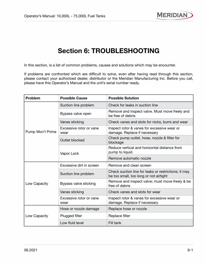
Section 6: TROUBLESHOOTING
In this section, is a list of common problems, causes and solutions which may be encounter.
If problems are confronted which are difficult to solve, even after having read through this section, please contact your authorized dealer, distributor or the Meridian Manufacturing Inc. Before you call, please have this Operator’s Manual and the unit’s serial number ready.
Problem Possible Cause Possible Solution
Pump Won’t Prime
Suction line problem Check for leaks in suction line
Bypass valve openRemove and inspect valve. Must move freely and be free of debris
Vanes sticking Check vanes and slots for nicks, burrs and wear
Excessive rotor or vane wear
Inspect rotor & vanes for excessive wear or damage. Replace if necessary
Outlet blockedCheck pump outlet, hose, nozzle & filter for blockage
Vapor Lock
Reduce vertical and horizontal distance from pump to liquid.
Remove automatic nozzle
Low Capacity
Excessive dirt in screen Remove and clean screen
Suction line problemCheck suction line for leaks or restrictions; it may be too small, too long or not airtight
Bypass valve stickingRemove and inspect valve; must move freely & be free of debris
Vanes sticking Check vanes and slots for wear
Excessive rotor or vane wear
Inspect rotor & vanes for excessive wear or damage. Replace if necessary
Low Capacity
Hose or nozzle damage Replace hose or nozzle
Plugged filter Replace filter
Low fluid level Fill tank

6-2 06.2021
Operator’s Manual: 10,000L - 75,000L Fuel Tanks
Problem Possible Cause Possible Solution
Pump runs slowly
Incorrect voltage Check incoming line voltage while pump is running
Vanes sticking Inspect vanes and slots for nicks, burrs and wear
Wiring problem Check for loose connections
Motor problem Return to place of purchase
Motor stalls
Bypass valve stickingRemove and inspect valve. Must move freely and be free of debris
Low voltage Check incoming line voltage while pump is running
Excessive rotor or vane wear
Check rotor & vanes for excessive wear or damage
Debris in pump cavity Clean debris from pump cavity
Motor overheats
Pumping high viscosity fluids
These fluids can only be pumped for short periods of time (less than 30 minutes duty cycle)
Clogged screen Remove and clean screen
Restricted suction pipe Remove and clean pipe
Motor failure Return to place of purchase
Pump rotor lock-up Clean and check pump rotor and vanes
Motor Inoperative
No power Check incoming power
Switch failure Return to place of purchase
Motor failure Return to place of purchase
Thermal protector failure Return to place of purchase
Incorrect/loose wiring Check wiring
Fluid Leakage
Bad O-ring gasket Check all O-ring gaskets
Dirty Shaft Seal Clean seal & seal cavity
Bad Shaft Seal Replace seal
Incompatible Fluid Refer wetted parts list to fluid manufacturer
Loose fasteners Tighten fasteners
Pump hums but will not operate
Dirt in Pump cavity Clean out pump cavity
Motor failure Return to place of purchase
Broken Key Remove all debris & replace key
06.2021 7-1
Operator’s Manual: 10,000L - 75,000L Fuel Tanks
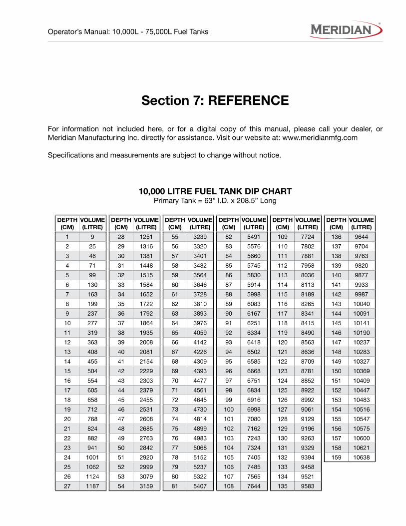
Section 7: REFERENCE
For information not included here, or for a digital copy of this manual, please call your dealer, or Meridian Manufacturing Inc. directly for assistance. Visit our website at: www.meridianmfg.com
Specifications and measurements are subject to change without notice.
10,000 LITRE FUEL TANK DIP CHARTPrimary Tank = 63” I.D. x 208.5” Long
DEPTH (CM)
VOLUME(LITRE)
1 9
2 25
3 46
4 71
5 99
6 130
7 163
8 199
9 237
10 277
11 319
12 363
13 408
14 455
15 504
16 554
17 605
18 658
19 712
20 768
21 824
22 882
23 941
24 1001
25 1062
26 1124
27 1187
DEPTH (CM)
VOLUME(LITRE)
28 1251
29 1316
30 1381
31 1448
32 1515
33 1584
34 1652
35 1722
36 1792
37 1864
38 1935
39 2008
40 2081
41 2154
42 2229
43 2303
44 2379
45 2455
46 2531
47 2608
48 2685
49 2763
50 2842
51 2920
52 2999
53 3079
54 3159
DEPTH (CM)
VOLUME(LITRE)
55 3239
56 3320
57 3401
58 3482
59 3564
60 3646
61 3728
62 3810
63 3893
64 3976
65 4059
66 4142
67 4226
68 4309
69 4393
70 4477
71 4561
72 4645
73 4730
74 4814
75 4899
76 4983
77 5068
78 5152
79 5237
80 5322
81 5407
DEPTH (CM)
VOLUME(LITRE)
82 5491
83 5576
84 5660
85 5745
86 5830
87 5914
88 5998
89 6083
90 6167
91 6251
92 6334
93 6418
94 6502
95 6585
96 6668
97 6751
98 6834
99 6916
100 6998
101 7080
102 7162
103 7243
104 7324
105 7405
106 7485
107 7565
108 7644
DEPTH (CM)
VOLUME(LITRE)
109 7724
110 7802
111 7881
112 7958
113 8036
114 8113
115 8189
116 8265
117 8341
118 8415
119 8490
120 8563
121 8636
122 8709
123 8781
124 8852
125 8922
126 8992
127 9061
128 9129
129 9196
130 9263
131 9329
132 9394
133 9458
134 9521
135 9583
DEPTH (CM)
VOLUME(LITRE)
136 9644
137 9704
138 9763
139 9820
140 9877
141 9933
142 9987
143 10040
144 10091
145 10141
146 10190
147 10237
148 10283
149 10327
150 10369
151 10409
152 10447
153 10483
154 10516
155 10547
156 10575
157 10600
158 10621
159 10638

7-2 06.2021
Operator’s Manual: 10,000L - 75,000L Fuel Tanks
DEPTH (CM)
VOLUME(LITRE)
1 7
2 21
3 39
4 59
5 83
6 109
7 137
8 167
9 199
10 233
11 268
12 305
13 343
14 383
15 424
16 467
17 510
18 555
19 601
20 649
21 697
22 746
23 796
24 848
25 900
26 953
27 1007
28 1062
29 1118
30 1174
31 1232
32 1290
33 1349
34 1409
35 1469
36 1530
37 1592
38 1655
39 1718
DEPTH (CM)
VOLUME(LITRE)
40 1782
41 1846
42 1911
43 1977
44 2043
45 2110
46 2177
47 2245
48 2313
49 2382
50 2452
51 2522
52 2592
53 2663
54 2735
55 2806
56 2879
57 2952
58 3025
59 3098
60 3172
61 3247
62 3321
63 3396
64 3472
65 3548
66 3624
67 3701
68 3777
69 3855
70 3932
71 4010
72 4088
73 4166
74 4245
75 4324
76 4403
77 4483
78 4562
DEPTH (CM)
VOLUME(LITRE)
79 4642
80 4723
81 4803
82 4884
83 4965
84 5046
85 5127
86 5208
87 5290
88 5372
89 5454
90 5536
91 5618
92 5700
93 5783
94 5866
95 5949
96 6031
97 6114
98 6198
99 6281
100 6364
101 6448
102 6531
103 6615
104 6698
105 6782
106 6866
107 6950
108 7033
109 7117
110 7201
111 7285
112 7369
113 7453
114 7537
115 7621
116 7705
117 7788
DEPTH (CM)
VOLUME(LITRE)
118 7872
119 7956
120 8040
121 8124
122 8207
123 8291
124 8374
125 8458
126 8541
127 8625
128 8708
129 8791
130 8874
131 8957
132 9039
133 9122
134 9204
135 9287
136 9369
137 9451
138 9533
139 9615
140 9696
141 9777
142 9859
143 9939
144 10020
145 10101
146 10181
147 10261
148 10341
149 10420
150 10500
151 10579
152 10658
153 10736
154 10814
155 10892
156 10970
DEPTH (CM)
VOLUME(LITRE)
157 11047
158 11124
159 11201
160 11277
161 11353
162 11429
163 11504
164 11579
165 11654
166 11728
167 11802
168 11875
169 11948
170 12020
171 12092
172 12164
173 12235
174 12306
175 12376
176 12446
177 12515
178 12584
179 12652
180 12719
181 12786
182 12853
183 12919
184 12984
185 13049
186 13113
187 13176
188 13239
189 13301
190 13363
191 13423
192 13483
193 13543
194 13601
195 13659
DEPTH (CM)
VOLUME(LITRE)
196 13716
197 13772
198 13827
199 13882
200 13935
201 13988
202 14039
203 14090
204 14140
205 14189
206 14236
207 14283
208 14328
209 14372
210 14415
211 14457
212 14498
213 14537
214 14574
215 14610
216 14645
217 14677
218 14708
219 14737
220 14764
221 14789
222 14810
223 14829
224 14845
225 14855
15,000 LITRE FUEL TANK DIP CHARTPrimary Tank = 88-3/4” I.D. x 146-7/8” Long

06.2021 7-3
Operator’s Manual: 10,000L - 75,000L Fuel Tanks
DEPTH (CM)
VOLUME(LITRE)
1 13
2 35
3 65
4 100
5 139
6 183
7 230
8 281
9 334
10 391
11 451
12 513
13 577
14 644
15 714
16 785
17 859
18 934
19 1012
20 1091
21 1172
22 1255
23 1340
24 1426
25 1514
26 1603
27 1694
28 1787
29 1880
30 1976
31 2072
32 2170
33 2269
34 2370
35 2471
36 2574
37 2678
38 2783
39 2889
DEPTH (CM)
VOLUME(LITRE)
40 2997
41 3105
42 3215
43 3325
44 3436
45 3549
46 3662
47 3776
48 3892
49 4008
50 4124
51 4242
52 4361
53 4480
54 4600
55 4721
56 4843
57 4965
58 5088
59 5212
60 5336
61 5461
62 5587
63 5713
64 5840
65 5968
66 6096
67 6225
68 6354
69 6484
70 6615
71 6745
72 6877
73 7009
74 7141
75 7274
76 7407
77 7541
78 7675
DEPTH (CM)
VOLUME(LITRE)
79 7809
80 7944
81 8080
82 8215
83 8351
84 8488
85 8624
86 8761
87 8898
88 9036
89 9174
90 9312
91 9450
92 9589
93 9728
94 9867
95 10006
96 10146
97 10286
98 10425
99 10565
100 10706
101 10846
102 10986
103 11127
104 11268
105 11409
106 11549
107 11690
108 11831
109 11972
110 12114
111 12255
112 12396
113 12537
114 12678
115 12819
116 12960
117 13102
DEPTH (CM)
VOLUME(LITRE)
118 13243
119 13384
120 13524
121 13665
122 13806
123 13947
124 14087
125 14228
126 14368
127 14508
128 14648
129 14788
130 14927
131 15067
132 15206
133 15345
134 15483
135 15622
136 15760
137 15898
138 16036
139 16173
140 16310
141 16447
142 16584
143 16720
144 16856
145 16991
146 17126
147 17261
148 17395
149 17529
150 17662
151 17795
152 17928
153 18060
154 18192
155 18323
156 18453
DEPTH (CM)
VOLUME(LITRE)
157 18583
158 18713
159 18842
160 18970
161 19098
162 19225
163 19352
164 19478
165 19603
166 19728
167 19852
168 19976
169 20098
170 20220
171 20341
172 20462
173 20582
174 20700
175 20818
176 20936
177 21052
178 21168
179 21282
180 21396
181 21509
182 21621
183 21731
184 21841
185 21950
186 22058
187 22165
188 22270
189 22375
190 22478
191 22580
192 22681
193 22781
194 22879
195 22976
DEPTH (CM)
VOLUME(LITRE)
196 23072
197 23167
198 23260
199 23351
200 23441
201 23530
202 23617
203 23702
204 23786
205 23868
206 23948
207 24026
208 24102
209 24177
210 24249
211 24319
212 24387
213 24453
214 24516
215 24577
216 24635
217 24690
218 24742
219 24790
220 24836
221 24877
222 24914
223 24946
224 24972
225 24989
25,000 LITRE FUEL TANK DIP CHARTPrimary Tank = 88-3/4” I.D. x 246-7/8” Long

7-4 06.2021
Operator’s Manual: 10,000L - 75,000L Fuel Tanks
DEPTH (CM)
VOLUME(LITRE)
1 18
2 50
3 91
4 140
5 195
6 256
7 323
8 394
9 469
10 549
11 632
12 719
13 810
14 904
15 1001
16 1101
17 1204
18 1310
19 1419
20 1530
21 1644
22 1760
23 1879
24 2000
25 2123
26 2249
27 2376
28 2506
29 2638
30 2771
31 2907
32 3044
33 3183
34 3324
35 3466
36 3611
37 3756
38 3904
39 4053
DEPTH (CM)
VOLUME(LITRE)
40 4204
41 4356
42 4509
43 4664
44 4820
45 4978
46 5137
47 5297
48 5458
49 5621
50 5785
51 5950
52 6117
53 6284
54 6452
55 6622
56 6793
57 6964
58 7137
59 7310
60 7485
61 7660
62 7837
63 8014
64 8192
65 8371
66 8551
67 8732
68 8913
69 9095
70 9278
71 9462
72 9646
73 9831
74 10016
75 10203
76 10390
77 10577
78 10765
DEPTH (CM)
VOLUME(LITRE)
79 10954
80 11143
81 11333
82 11523
83 11714
84 11905
85 12097
86 12289
87 12481
88 12674
89 12868
90 13062
91 13256
92 13450
93 13645
94 13840
95 14036
96 14231
97 14427
98 14623
99 14820
100 15016
101 15213
102 15410
103 15607
104 15805
105 16002
106 16200
107 16398
108 16595
109 16793
110 16991
111 17189
112 17387
113 17585
114 17783
115 17981
116 18179
117 18377
DEPTH (CM)
VOLUME(LITRE)
118 18575
119 18772
120 18970
121 19168
122 19365
123 19562
124 19759
125 19956
126 20153
127 20350
128 20546
129 20742
130 20938
131 21133
132 21328
133 21523
134 21718
135 21912
136 22106
137 22300
138 22493
139 22686
140 22878
141 23070
142 23261
143 23452
144 23643
145 23833
146 24022
147 24211
148 24399
149 24587
150 24774
151 24961
152 25147
153 25332
154 25517
155 25700
156 25884
DEPTH (CM)
VOLUME(LITRE)
157 26066
158 26248
159 26429
160 26609
161 26788
162 26967
163 27144
164 27321
165 27497
166 27672
167 27846
168 28019
169 28191
170 28362
171 28532
172 28701
173 28869
174 29036
175 29201
176 29366
177 29529
178 29691
179 29852
180 30011
181 30169
182 30326
183 30482
184 30636
185 30788
186 30940
187 31089
188 31237
189 31384
190 31529
191 31672
192 31814
193 31954
194 32092
195 32228
DEPTH (CM)
VOLUME(LITRE)
196 32362
197 32495
198 32625
199 32754
200 32880
201 33004
202 33126
203 33246
204 33363
205 33478
206 33590
207 33700
208 33807
209 33912
210 34013
211 34112
212 34207
213 34299
214 34388
215 34473
216 34554
217 34631
218 34704
219 34772
220 34836
221 34894
222 34945
223 34990
224 35026
225 35051
35,000 LITRE FUEL TANK DIP CHARTPrimary Tank = 88-3/4” I.D. x 348-3/4” Long

06.2021 7-5
Operator’s Manual: 10,000L - 75,000L Fuel Tanks
DEPTH (CM)
VOLUME(LITRE)
1 16
2 46
3 85
4 130
5 182
6 239
7 300
8 367
9 437
10 511
11 589
12 671
13 756
14 844
15 935
16 1029
17 1125
18 1225
19 1327
20 1432
21 1539
22 1648
23 1760
24 1874
25 1990
26 2109
27 2229
28 2352
29 2476
30 2603
31 2731
32 2861
33 2993
34 3127
35 3262
36 3399
37 3538
38 3678
39 3820
40 3964
41 4109
42 4255
43 4403
DEPTH (CM)
VOLUME(LITRE)
44 4553
45 4704
46 4856
47 5009
48 5164
49 5321
50 5478
51 5637
52 5797
53 5958
54 6121
55 6285
56 6449
57 6615
58 6782
59 6951
60 7120
61 7290
62 7461
63 7634
64 7807
65 7982
66 8157
67 8333
68 8511
69 8689
70 8868
71 9048
72 9229
73 9410
74 9593
75 9776
76 9960
77 10145
78 10331
79 10518
80 10705
81 10893
82 11082
83 11272
84 11462
85 11653
86 11844
DEPTH (CM)
VOLUME(LITRE)
87 12037
88 12230
89 12423
90 12617
91 12812
92 13008
93 13204
94 13400
95 13597
96 13795
97 13993
98 14192
99 14392
100 14591
101 14792
102 14993
103 15194
104 15396
105 15598
106 15801
107 16004
108 16207
109 16411
110 16616
111 16820
112 17025
113 17231
114 17437
115 17643
116 17850
117 18056
118 18264
119 18471
120 18679
121 18887
122 19095
123 19304
124 19513
125 19722
126 19932
127 20141
128 20351
129 20561
DEPTH (CM)
VOLUME(LITRE)
130 20771
131 20982
132 21192
133 21403
134 21614
135 21825
136 22036
137 22248
138 22459
139 22671
140 22883
141 23094
142 23306
143 23518
144 23730
145 23942
146 24155
147 24367
148 24579
149 24791
150 25003
151 25216
152 25428
153 25640
154 25852
155 26065
156 26277
157 26489
158 26701
159 26913
160 27124
161 27336
162 27548
163 27759
164 27971
165 28182
166 28393
167 28604
168 28815
169 29025
170 29236
171 29446
172 29656
DEPTH (CM)
VOLUME(LITRE)
173 29866
174 30076
175 30285
176 30494
177 30703
178 30912
179 31120
180 31328
181 31536
182 31744
183 31951
184 32158
185 32364
186 32570
187 32776
188 32982
189 33187
190 33392
191 33596
192 33800
193 34004
194 34207
195 34409
196 34612
197 34813
198 35015
199 35216
200 35416
201 35616
202 35815
203 36014
204 36212
205 36410
206 36607
207 36804
208 37000
209 37195
210 37390
211 37585
212 37778
213 37971
214 38163
215 38355
DEPTH (CM)
VOLUME(LITRE)
216 38546
217 38736
218 38926
219 39115
220 39303
221 39490
222 39677
223 39863
224 40048
225 40232
226 40415
227 40598
228 40780
229 40960
230 41140
231 41320
232 41498
233 41675
234 41851
235 42027
236 42201
237 42375
238 42547
239 42718
240 42889
241 43058
242 43226
243 43393
244 43559
245 43724
246 43888
247 44051
248 44212
249 44372
250 44531
251 44688
252 44845
253 45000
254 45153
255 45306
256 45457
257 45606
258 45754
DEPTH (CM)
VOLUME(LITRE)
259 45901
260 46046
261 46189
262 46332
263 46472
264 46611
265 46748
266 46883
267 47017
268 47149
269 47279
270 47408
271 47534
272 47659
273 47781
274 47902
275 48020
276 48137
277 48251
278 48363
279 48472
280 48579
281 48684
282 48786
283 48886
284 48983
285 49077
286 49168
287 49256
288 49341
289 49423
290 49501
291 49575
292 49646
293 49712
294 49774
295 49831
296 49883
297 49929
298 49968
299 49998
300 50015
50,000 LITRE FUEL TANK DIP CHARTPrimary Tank = 118’’ I.D. x 279” Long

7-6 06.2021
Operator’s Manual: 10,000L - 75,000L Fuel Tanks
DEPTH (CM)
VOLUME(LITRE)
1 21
2 60
3 110
4 169
5 237
6 311
7 391
8 477
9 569
10 666
11 767
12 873
13 984
14 1098
15 1217
16 1339
17 1465
18 1594
19 1727
20 1864
21 2003
22 2145
23 2291
24 2439
25 2591
26 2745
27 2902
28 3061
29 3223
30 3387
31 3554
32 3724
33 3895
34 4070
35 4246
36 4424
37 4605
38 4788
39 4972
40 5159
41 5348
42 5539
43 5731
DEPTH (CM)
VOLUME(LITRE)
44 5926
45 6122
46 6320
47 6520
48 6722
49 6925
50 7131
51 7337
52 7546
53 7755
54 7967
55 8180
56 8395
57 8611
58 8828
59 9047
60 9267
61 9489
62 9712
63 9936
64 10162
65 10389
66 10617
67 10847
68 11077
69 11309
70 11542
71 11777
72 12012
73 12249
74 12486
75 12725
76 12965
77 13206
78 13447
79 13690
80 13934
81 14179
82 14425
83 14671
84 14919
85 15167
86 15417
DEPTH (CM)
VOLUME(LITRE)
87 15667
88 15918
89 16170
90 16423
91 16677
92 16931
93 17186
94 17442
95 17699
96 17956
97 18214
98 18473
99 18732
100 18992
101 19253
102 19515
103 19777
104 20039
105 20303
106 20566
107 20831
108 21096
109 21361
110 21627
111 21894
112 22161
113 22428
114 22696
115 22964
116 23233
117 23503
118 23772
119 24042
120 24313
121 24584
122 24855
123 25126
124 25398
125 25671
126 25943
127 26216
128 26489
129 26763
DEPTH (CM)
VOLUME(LITRE)
130 27036
131 27310
132 27584
133 27859
134 28133
135 28408
136 28683
137 28958
138 29233
139 29509
140 29784
141 30060
142 30336
143 30612
144 30888
145 31164
146 31440
147 31716
148 31992
149 32269
150 32545
151 32821
152 33097
153 33374
154 33650
155 33926
156 34202
157 34478
158 34754
159 35030
160 35306
161 35581
162 35857
163 36132
164 36407
165 36682
166 36957
167 37231
168 37506
169 37780
170 38054
171 38327
172 38601
DEPTH (CM)
VOLUME(LITRE)
173 38874
174 39147
175 39419
176 39692
177 39964
178 40235
179 40506
180 40777
181 41048
182 41318
183 41588
184 41857
185 42126
186 42394
187 42662
188 42930
189 43197
190 43463
191 43729
192 43995
193 44260
194 44524
195 44788
196 45051
197 45314
198 45576
199 45837
200 46098
201 46358
202 46618
203 46876
204 47135
205 47392
206 47649
207 47905
208 48160
209 48414
210 48668
211 48921
212 49173
213 49424
214 49674
215 49923
DEPTH (CM)
VOLUME(LITRE)
216 50172
217 50420
218 50666
219 50912
220 51157
221 51401
222 51644
223 51886
224 52127
225 52366
226 52605
227 52843
228 53079
229 53315
230 53549
231 53782
232 54014
233 54245
234 54474
235 54703
236 54930
237 55155
238 55380
239 55603
240 55825
241 56045
242 56264
243 56482
244 56698
245 56912
246 57125
247 57337
248 57547
249 57755
250 57962
251 58167
252 58371
253 58572
254 58772
255 58971
256 59167
257 59362
258 59554
DEPTH (CM)
VOLUME(LITRE)
259 59745
260 59934
261 60121
262 60306
263 60489
264 60669
265 60848
266 61024
267 61198
268 61370
269 61540
270 61707
271 61871
272 62033
273 62193
274 62350
275 62504
276 62655
277 62804
278 62949
279 63092
280 63232
281 63368
282 63501
283 63631
284 63757
285 63879
286 63998
287 64112
288 64223
289 64329
290 64431
291 64528
292 64620
293 64706
294 64787
295 64861
296 64928
297 64988
298 65039
299 65078
300 65100
65,000 LITRE FUEL TANK DIP CHARTPrimary Tank = 118” I.D. x 363” Long
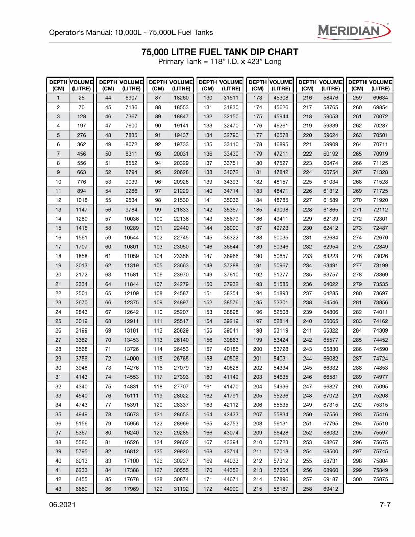
06.2021 7-7
Operator’s Manual: 10,000L - 75,000L Fuel Tanks
DEPTH(CM)
VOLUME(LITRE)
1 25
2 70
3 128
4 197
5 276
6 362
7 456
8 556
9 663
10 776
11 894
12 1018
13 1147
14 1280
15 1418
16 1561
17 1707
18 1858
19 2013
20 2172
21 2334
22 2501
23 2670
24 2843
25 3019
26 3199
27 3382
28 3568
29 3756
30 3948
31 4143
32 4340
33 4540
34 4743
35 4949
36 5156
37 5367
38 5580
39 5795
40 6013
41 6233
42 6455
43 6680
DEPTH(CM)
VOLUME(LITRE)
44 6907
45 7136
46 7367
47 7600
48 7835
49 8072
50 8311
51 8552
52 8794
53 9039
54 9286
55 9534
56 9784
57 10036
58 10289
59 10544
60 10801
61 11059
62 11319
63 11581
64 11844
65 12109
66 12375
67 12642
68 12911
69 13181
70 13453
71 13726
72 14000
73 14276
74 14553
75 14831
76 15111
77 15391
78 15673
79 15956
80 16240
81 16526
82 16812
83 17100
84 17388
85 17678
86 17969
DEPTH(CM)
VOLUME(LITRE)
87 18260
88 18553
89 18847
90 19141
91 19437
92 19733
93 20031
94 20329
95 20628
96 20928
97 21229
98 21530
99 21833
100 22136
101 22440
102 22745
103 23050
104 23356
105 23663
106 23970
107 24279
108 24587
109 24897
110 25207
111 25517
112 25829
113 26140
114 26453
115 26765
116 27079
117 27393
118 27707
119 28022
120 28337
121 28653
122 28969
123 29285
124 29602
125 29920
126 30237
127 30555
128 30874
129 31192
DEPTH(CM)
VOLUME(LITRE)
130 31511
131 31830
132 32150
133 32470
134 32790
135 33110
136 33430
137 33751
138 34072
139 34393
140 34714
141 35036
142 35357
143 35679
144 36000
145 36322
146 36644
147 36966
148 37288
149 37610
150 37932
151 38254
152 38576
153 38898
154 39219
155 39541
156 39863
157 40185
158 40506
159 40828
160 41149
161 41470
162 41791
163 42112
164 42433
165 42753
166 43074
167 43394
168 43714
169 44033
170 44352
171 44671
172 44990
DEPTH(CM)
VOLUME(LITRE)
173 45308
174 45626
175 45944
176 46261
177 46578
178 46895
179 47211
180 47527
181 47842
182 48157
183 48471
184 48785
185 49098
186 49411
187 49723
188 50035
189 50346
190 50657
191 50967
192 51277
193 51585
194 51893
195 52201
196 52508
197 52814
198 53119
199 53424
200 53728
201 54031
202 54334
203 54635
204 54936
205 55236
206 55535
207 55834
208 56131
209 56428
210 56723
211 57018
212 57312
213 57604
214 57896
215 58187
DEPTH(CM)
VOLUME(LITRE)
216 58476
217 58765
218 59053
219 59339
220 59624
221 59909
222 60192
223 60474
224 60754
225 61034
226 61312
227 61589
228 61865
229 62139
230 62412
231 62684
232 62954
233 63223
234 63491
235 63757
236 64022
237 64285
238 64546
239 64806
240 65065
241 65322
242 65577
243 65830
244 66082
245 66332
246 66581
247 66827
248 67072
249 67315
250 67556
251 67795
252 68032
253 68267
254 68500
255 68731
256 68960
257 69187
258 69412
DEPTH(CM)
VOLUME(LITRE)
259 69634
260 69854
261 70072
262 70287
263 70501
264 70711
265 70919
266 71125
267 71328
268 71528
269 71725
270 71920
271 72112
272 72301
273 72487
274 72670
275 72849
276 73026
277 73199
278 73369
279 73535
280 73697
281 73856
282 74011
283 74162
284 74309
285 74452
286 74590
287 74724
288 74853
289 74977
290 75095
291 75208
292 75315
293 75416
294 75510
295 75597
296 75675
297 75745
298 75804
299 75849
300 75875
75,000 LITRE FUEL TANK DIP CHARTPrimary Tank = 118” I.D. x 423” Long
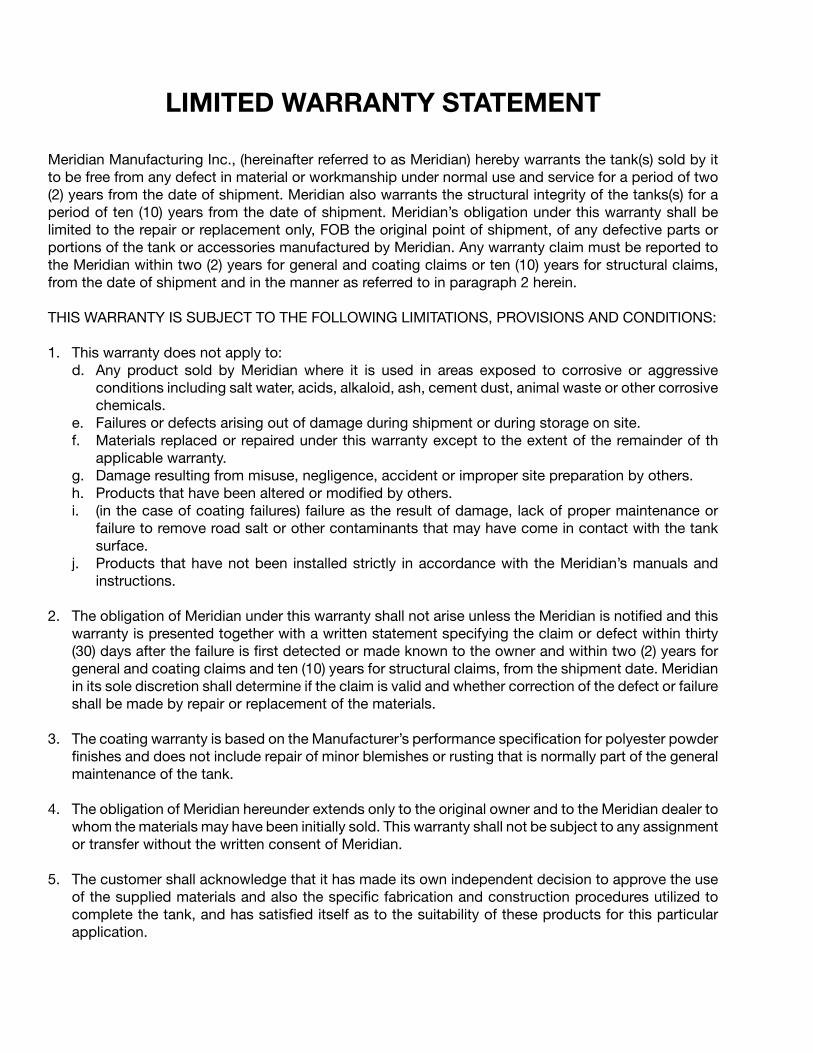
LIMITED WARRANTY STATEMENT
Meridian Manufacturing Inc., (hereinafter referred to as Meridian) hereby warrants the tank(s) sold by it to be free from any defect in material or workmanship under normal use and service for a period of two (2) years from the date of shipment. Meridian also warrants the structural integrity of the tanks(s) for aperiod of ten (10) years from the date of shipment. Meridian’s obligation under this warranty shall belimited to the repair or replacement only, FOB the original point of shipment, of any defective parts orportions of the tank or accessories manufactured by Meridian. Any warranty claim must be reported tothe Meridian within two (2) years for general and coating claims or ten (10) years for structural claims,from the date of shipment and in the manner as referred to in paragraph 2 herein.
THIS WARRANTY IS SUBJECT TO THE FOLLOWING LIMITATIONS, PROVISIONS AND CONDITIONS:
1. This warranty does not apply to:d. Any product sold by Meridian where it is used in areas exposed to corrosive or aggressive
conditions including salt water, acids, alkaloid, ash, cement dust, animal waste or other corrosivechemicals.
e. Failures or defects arising out of damage during shipment or during storage on site.f. Materials replaced or repaired under this warranty except to the extent of the remainder of th
applicable warranty.g. Damage resulting from misuse, negligence, accident or improper site preparation by others.h. Products that have been altered or modified by others.i. (in the case of coating failures) failure as the result of damage, lack of proper maintenance or
failure to remove road salt or other contaminants that may have come in contact with the tanksurface.
j. Products that have not been installed strictly in accordance with the Meridian’s manuals andinstructions.
2. The obligation of Meridian under this warranty shall not arise unless the Meridian is notified and thiswarranty is presented together with a written statement specifying the claim or defect within thirty(30) days after the failure is first detected or made known to the owner and within two (2) years forgeneral and coating claims and ten (10) years for structural claims, from the shipment date. Meridianin its sole discretion shall determine if the claim is valid and whether correction of the defect or failureshall be made by repair or replacement of the materials.
3. The coating warranty is based on the Manufacturer’s performance specification for polyester powderfinishes and does not include repair of minor blemishes or rusting that is normally part of the generalmaintenance of the tank.
4. The obligation of Meridian hereunder extends only to the original owner and to the Meridian dealer towhom the materials may have been initially sold. This warranty shall not be subject to any assignmentor transfer without the written consent of Meridian.
5. The customer shall acknowledge that it has made its own independent decision to approve the useof the supplied materials and also the specific fabrication and construction procedures utilized tocomplete the tank, and has satisfied itself as to the suitability of these products for this particularapplication.

6. The foregoing sets forth the only warranties applicable to said materials and said warranties aregiven expressly and in lieu of all other warranties, expressed or implied, statutory or otherwise, ofmerchantability or fitness for a particular purpose and all warranties which exceed or differ from saidwarranties herein are disclaimed by the Manufacturer.
7. The owners sole and exclusive remedy against Meridian shall be limited to the applicable warrantyset forth herein and the endorsements, if any, issued together with this document and no otherremedy (including but not limited to the recovery of assembly or disassembly costs, shipping costs,direct, incidental, special, indirect or consequential damages for lost profits, lost sales, injury toperson or property or any other loss, whether arising from breach of contract, breach of warranty,tort, including negligence, strict liability or otherwise) shall be available to the owner or MeridianDealer or any other person or entitles whether by direct action or for contribution or indemnity orotherwise.
8. The financial obligation of Meridian under this warranty shall be limited to the repair or replacementof the product as originally supplied and in no event shall exceed the original cost of the productsupplied.
9. Meridian shall not have any obligation under any warranty herein until all accounts for materials,installation and erection of the said product thereof and for labor and other work performed byMeridian or its dealers have been paid in full by the owner.
Register your product at: www.merdianmfg.comFor warranty information send an email to: [email protected]
WARRANTY REQUEST PROCEDURE
1. The product must be registered with Meridian Manufacturing Inc.
2. The purchaser must contact the dealer, from where the unit was purchased, immediately upondiscovery of any defects.
3. A completed Warranty Request Form must be submitted by the dealer to Meridian’s warrantyrepresentative for review and any subsequent course of action.- Warranty requests must be completed with ALL required information in order for it to be considered
for approval.- Send photographs of the entire piece of equipment, and of the specific area of concern.
4. Warranty repair work will only be performed by Meridian or an approved representative of Meridian.Warranty work completed prior to Meridian’s approval will NOT be honoured. Failure to follow thisprocedure may affect any or all of this warranty.
5. All warranty requests will be adjudicated at the sole discretion of Meridian and in accordance withthe terms and conditions of the warranty.

Camrose, AB (800) 830-2467Lethbridge, AB: (800) 661-1436
Winkler, MB: (800) 665-7259www.meridianmfg.com | [email protected]
©2021 Meridian Manufacturing Inc. Registered Trademarks Used Under License. Printed in Canada (06/2021) Part No: 11098-REV1