100 Mbps Compact Media Converter - ftp.blackbox.comftp.blackbox.com/anonymous/manuals/L/LHC038A.pdf1...
8
100 Mbps Compact Media Converter Order toll-free in the U.S.: 877-877-BBOX (outside U.S. call 724-746-5500) FREE technical support, 24 hours a day, 7 days a week: Call 724-746-5500 or fax 724-746-0746 Mail order: Black Box Corporation, 1000 Park Drive, Lawrence, PA 15055-1018 Web site: www.blackbox.com • E-mail: [email protected] CUSTOMER SUPPORT INFORMATION December 2006 LHC001A-R4 - LHC002A-R4 LHC005A-R4 - LHC006A-R4 LHC007A-MT-R3 - LHC008A-R3 LHC009A-R3 - LHC5129A-R3 LHC5130A-R3 - LHC5132A-R3 LHC5133A-R3 - LHC5134A LHC5135A - LHC037A LHC038A - LHC039A LMC7030A - LMC7031A © Copyright 2006. Black Box Corporation. All rights reserved 1000 Park Drive * Lawrence, PA. 15055-1018 * 724-746-5500 * Fax 724-746-0746 Document Number 55-80128BB-00 A5 December 2006
-
Upload
nguyenthien -
Category
Documents
-
view
224 -
download
0
Transcript of 100 Mbps Compact Media Converter - ftp.blackbox.comftp.blackbox.com/anonymous/manuals/L/LHC038A.pdf1...

100 MbpsCompact Media Converter
Order toll-free in the U.S.: 877-877-BBOX (outside U.S. call 724-746-5500)FREE technical support, 24 hours a day, 7 days a week: Call 724-746-5500 or fax 724-746-0746Mail order: Black Box Corporation, 1000 Park Drive, Lawrence, PA 15055-1018Web site: www.blackbox.com • E-mail: [email protected]
CUSTOMERSUPPORT
INFORMATION
December 2006LHC001A-R4 - LHC002A-R4LHC005A-R4 - LHC006A-R4
LHC007A-MT-R3 - LHC008A-R3LHC009A-R3 - LHC5129A-R3
LHC5130A-R3 - LHC5132A-R3LHC5133A-R3 - LHC5134A
LHC5135A - LHC037ALHC038A - LHC039A
LMC7030A - LMC7031A
© Copyright 2006. Black Box Corporation. All rights reserved
1000 Park Drive * Lawrence, PA. 15055-1018 * 724-746-5500 * Fax 724-746-0746
Document Number 55-80128BB-00 A5 December 2006

Notes:Notes:

11
Table of Contents
About the 100 Mbps Compact Media Converter . . . . . . . . .1LED Indicators . . . . . . . . . . . . . . . . . . . . . . . . . . . . . . . . . . .2Installing the 100 Mbps Compact Media Converter . . . . . .3Configuring the 100 Mbps Compact Media Converter . . . .4About FiberAlert and LinkLoss . . . . . . . . . . . . . . . . . . . . . .5Specifications . . . . . . . . . . . . . . . . . . . . . . . . . . . . . . . . . . . .7Black Box Customer Service . . . . . . . . . . . . . . . . . . . . . . . .8Fiber Optic Cleaning Guidelines . . . . . . . . . . . . . . . . . . . . .8Electrostatic Discharge Precautions . . . . . . . . . . . . . . . . . . .9Warranty . . . . . . . . . . . . . . . . . . . . . . . . . . . . . . . . . . . . . . . .9Federal Communications Commission Radio Frequency Interference Statement . . . . . . . . . . . . . . .10
European Directive 2002/96/EC (WEEE) requires that anyequipment that bears this symbol on product or packagingmust not be disposed of with unsorted municipal waste. Thissymbol indicates that the equipment should be disposed ofseparately from regular household waste. It is the consumer'sresponsibility to dispose of this and all equipment so markedthrough designated collection facilities appointed by govern-ment or local authorities. Following these steps through prop-er disposal and recycling will help prevent potential negativeconsequences to the environment and human health. Formore detailed information about proper disposal, please con-tact local authorities, waste disposal services, or the point ofpurchase for this equipment.

1 10
About the 100 Mbps Compact Media ConverterThe Compact Media Converter converts between 100 Mbps twisted pair and
100 Mbps multi-mode or single-mode fiber. It is available with one RJ-45 con-nector for the twisted pair port and several types of fiber connectors, including ST,SC and MT, for the fiber port. Single-strand fiber versions are also available. This1U high, standalone unit includes diagnostic LEDs for each port and a universal(100/240 VAC) power supply.
LHC001A-R4 TX/FX-MM1300-ST, 2 kmLHC002A-R4 TX/FX-MM1300-SC, 2 kmLHC005A-R4 TX/FX-SM1310/PLUS-ST, 40 kmLHC006A-R4 TX/FX-SM1310/PLUS-SC, 40 kmLHC007A-MT-R3 TX/FX-MM1300-MT, 2 kmLHC008A-R3 TX/SX-MM850-ST, 300 mLHC009A-R3 TX/SX-MM850-SC, 300 mLHC037A TX/FX-SM1310/LONG-ST, 80 kmLHC038A TX/FX-SM1310/LONG-SC, 80 kmLHC039A TX/FX-SM1550/LONG-SC, 100 km
Single Strand Products:LMC7030A TX/SSFX-MM1310-SC (1310xmt/1550rcv), 2 kmLMC7031A TX/SSFX-MM1550-SC (1550xmt/1310rcv), 2 kmLHC5129A-R3 TX/SSFX-SM1310-SC (1310xmt/1550rcv), 20 kmLHC5130A-R3 TX/SSFX-SM1550-SC (1550xmt/1310rcv), 20 kmLHC5132A-R3 TX/SSFX-SM1310/PLUS-SC (1310xmt/1550rcv), 40 kmLHC5133A-R3 TX/SSFX-SM1550/PLUS-SC (1550xmt/1310rcv), 40 kmLHC5134A TX/SSFX-SM1310/LONG-SC (1310xmt/1550rcv), 60 kmLHC5135A TX/SSFX-SM1550/LONG-SC (1550xmt/1310rcv), 60 km
Federal Communication Commission RadioFrequency Interference Statement
This equipment has been tested and found to comply with the limits for aClass B computing device, pursuant to Part 15 of the FCC Rules. These limitsare designed to provide reasonable protection against harmful interference whenthe equipment is operated in a commercial environment. This equipment gener-ates, uses and can radiate radio frequency energy and, if not installed and used inaccordance with the instruction manual, may cause harmful interference to radiocommunications. Operation of this equipment in a residential area is likely tocause harmful interference in which the user will be required to correct the inter-ference at his own expense.
Any changes or modifications not expressly approved by the manufacturercould void the user's authority to operate the equipment.
The use of non-shielded I/O cables may not guarantee compliance with FCCRFI limits. This digital apparatus does not exceed the Class B limits for radionoise emission from digital apparatus set out in the Radio InterferenceRegulation of the Canadian Department of Communications.
Le présent appareil numérique n’émet pas de bruits radioélectriques dépas-sant les limites applicables aux appareils numériques de classe B prescrites dansle Règlement sur le brouillage radioélectrique publié par le ministère desCommunications du Canada.
9 2
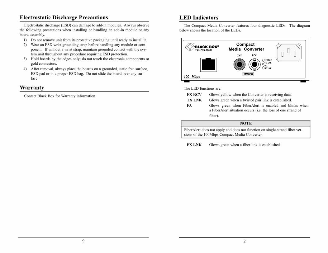
LED IndicatorsThe Compact Media Converter features four diagnostic LEDs. The diagram
below shows the location of the LEDs.
The LED functions are:FX RCV Glows yellow when the Converter is receiving data.TX LNK Glows green when a twisted pair link is established.FA Glows green when FiberAlert is enabled and blinks when
a FiberAlert situation occurs (i.e. the loss of one strand of fiber).
FX LNK Glows green when a fiber link is established.
Electrostatic Discharge PrecautionsElectrostatic discharge (ESD) can damage to add-in modules. Always observe
the following precautions when installing or handling an add-in module or anyboard assembly.
1) Do not remove unit from its protective packaging until ready to install it.2) Wear an ESD wrist grounding strap before handling any module or com-
ponent. If without a wrist strap, maintain grounded contact with the sys-tem unit throughout any procedure requiring ESD protection.
3) Hold boards by the edges only; do not touch the electronic components orgold connectors.
4) After removal, always place the boards on a grounded, static free surface,ESD pad or in a proper ESD bag. Do not slide the board over any sur-face.
WarrantyContact Black Box for Warranty information.
NOTEFiberAlert does not apply and does not function on single-strand fiber ver-sions of the 100Mbps Compact Media Converter.
3 8
Installing the 100 Mbps Compact Media ConverterWhile the 100 Mbps Compact Media Converter comes ready to install, all con-
figuration changes should be made after installation. To install the Compact MediaConverter, make sure the unit is placed on a suitably flat surface. Then, attach thecables between the Compact Media Converter and each device that will be inter-connected. Finally, plug the unit into a reliable, filtered power source.
INSTALLATION TROUBLESHOOTING
To test the 100 Mbps Compact Media Converter during installation, first test thefiber and twisted pair connections with all troubleshooting features disabled, thenenable these features, if desired, just before final installation. This will reduce thefeatures’ interference with testing.When working with units whose features cannot be disabled, both twisted pair andfiber cables must be connected before the link LEDs will light.To test a media converter by itself, first verify that an appropriate fiber patch cableis being used. Then, follow these steps:
Step 1: Connect the media converter to the twisted pair devicewith a twisted pair cable.Step 2: Loop a single strand of fiber from the transmit port tothe receive port of your media converter.Step 3: Verify that both twisted pair and fiber link LEDs lighton the Compact Media Converter.
Use the appropriate twisted pair cable, and have the crossover/pass-through switchset correctly.
If using a high powered device designed for long distance installations in a shortdistance installation, an optical attenuator may be needed to prevent data loss on aconnection.
Contact Black Box for more information.
Black Box Customer ServiceOrder toll-free in the U.S.: Call 877-877-BBOX
(outside U.S. call 724-746-5500)FREE technical support, 24 hours a day, 7 days a week
Call: 724-746-5500 or Fax: 724-746-0746Mail order: Black Box Corporation
1000 Park Drive, Lawrence, PA 15055-1018Web site: www.blackbox.com E-mail: [email protected]
Fiber Optic Cleaning GuidelinesFiber optic equipment is extremely susceptible to contamination by particles of
dirt or dust which can obstruct the optics and cause performance degradation.Good system performance requires clean optics and connector ferrules.
1) Only use fiber patch cords (or connectors) from a reputable supplier; low-quality components can cause many hard-to-diagnose problems.
2) Black Box installs dust caps to ensure factory-clean optical devices. Theseprotective caps should not be removed until the moment of connecting thefiber cable to the device. Assure that the fiber is properly terminated, pol-ished and free of any dust or dirt and that the location is as free from dust anddirt as possible.
3) Store spare caps in a dust-free environment such as a sealed plastic bag orbox so reinstalled caps do not introduce any contamination to the optics.
4) Reinstall the protective caps when disconnecting the fiber device.5) To clean contaminated optics, alternate between blasting with clean, dry,
compressed air and flushing with methanol to remove particles of dirt.
NOTESince single-strand fiber products use optics that transmit and receive ontwo different wavelengths, deploy single-strand fiber products in pairs,or connect two compatible Black Box single-strand fiber products.
WARNINGIntegrated circuits and fiber optic components are extremely susceptible toelectrostatic discharge damage. Only qualified service technicians using toolsand techniques comforming to accepted industry practices should handle thesecomponents.

7 4
What Is Pulsing FiberAlert?Pulsing FiberAlert provides the same function as FiberAlert but, rather than
ceasing transmission when the receiving unit goes down, Pulsing FiberAlert sendspulses through the line so that once the receiving unit starts to function, transmis-sion commences. Use Pulsing FiberAlert in the following two situations:
A) When connecting two Compact Media Converter units (or connecting a PSE-Compact Media Converter to a 100 Mbps Module TX/FX) withFiberAlert enabled.B) When connecting one Compact Media Converter with FiberAlert enabledand one 10/100 Autosensing unit with Link Fault Detection (LFD) enabled.
SpecificationsEnvironmental
Operating Temperature: 32° - 122° F (0° - 50° C)Storage Temperature: 0° - 160° F (-20° - 70° C)Humidity: 5 - 95% (non-condensing)
PowerAC Input Load: 100-240VAC ±10%, 50/60 Hz, 1.5AHeat generated: 51 BTU/hr.
Dimensions1.64”H x 4.75”W x 4.95”D (4.17 cm x 12.07 cm x 12.57 cm)
Configuring the 100 Mbps Compact Media ConverterThe 100 Mbps Compact Media Converter
features an 8-position DIP switch for configur-ing the unit after installation. This switch isaccessed through a cut-out in the bottom. Afterconfiguring the DIP switch, power cycle theCompact Media Converter for the changes totake effect. Default settings for the followingfeatures are shown in the diagram.
• AN ENABLED (Auto-Negotiation)• MDI/MDI-X (Manual port setting)• AUTO MDI/MDI-X (AutoCross)• TX LL (TX LinkLoss)• FX LL (FX LinkLoss)• FA ENABLED (FiberAlert)• FA PULSE (Pulsing FiberAlert)
Some switches are reserved for future development.
Twisted Pair Crossover/Pass-Through ConnectionsWhether using crossover or straight-through CAT5 twisted pair cabling, the 100
Mbps Compact Media Converter will support both types of connections by one ofthe following methods:
AutoCross (Switch 4): The Compact Media Converter includes AutoCross, afeature which automatically selects between a crossover workstation or pass-through/ repeater hub connection depending on the connected device. To enableAutoCross, move the Auto MDI/MDI-X switch to the ON position.
MDI/MDI-X (Switch 3): To manually configure the Compact Media Converterfor a pass-through (MDI) or a crossover (MDI-X) connection, set Switch 4 to OFFand set Switch 3 to the desired connection type: MDI=OFF and MDI-X=ON. Ifunsure about the type of connection, set the DIP switch to a position that makes thetwisted pair LNK (link) LED glow.
Auto-NegotiationAuto-Negotiation, enabled by default, allows the Compact Media Converter to
communicate at the speed and duplex settings of the device to which it is connect-ed. Therefore, if the device connected to the Compact Media Converter sends andreceives at 100Mbps, Full-Duplex, so will the Compact Media Converter. This willfunction within the operating parameters of the Compact Media Converter(10/100Mbps, Half or Full Duplex).
To make the Compact Media Converter only communicate at one speed or oneduplex setting, Auto-Negotiation will need to be turned off.
Converter 1 Converter 2FiberAlert Enabled FiberAlert and Pulsing FiberAlert Enabled
FiberAlert Enabled FiberAlert Disabled
INSTALLATION TIPEnable FiberAlert and/or Pulsing FiberAlert on only ONE side of a media con-version; enabling it on both sides will keep both transmitters off indefinitely.
5 6
About FiberAlert and LinkLossThe Compact Media Converter comes with the following troubleshooting fea-
tures:• FX LinkLoss (LinkLoss over a Fiber cable)• TX LinkLoss (LinkLoss over a Twisted Pair cable)• FiberAlert (including Pulsing FiberAlert)LinkLoss and FiberAlert are advanced troubleshooting features that can help
locate "silent failures" on a network. Users should understand how FiberAlert andLinkLoss work, and how they will act in a network environment, before attempt-ing to install the Compact Media Converter.
About Link IntegrityDuring normal operation, link integrity pulses are transmitted by all point-to-
point Ethernet devices. When a Compact Media Converter receives valid link puls-es, it knows that the device to which it is connected is functioning, and that the cop-per or fiber cable coming from that device is intact. The appropriate “LINK” LEDis lit to indicate this. The Compact Media Converter also sends out link pulsesfrom its copper and fiber transmitters, but normally has no way of knowingwhether the cable to the other device is intact and the link pulses are reaching theother end. FiberAlert and LinkLoss allow this information to be obtained from thefiber, even when physical access to a remote device (and its link integrity LED) isnot available.
What Is FX LinkLoss?FX LinkLoss is a troubleshooting feature that allows users to detect failures over
the fiber connection. When a fault occurs on the fiber segment of a conversion, FXLinkLoss detects the fault and passes this information to the twisted pair segment.If a Compact Media Converter is not receiving a fiber link, FX LinkLoss disablesthe transmitter on the Compact Media Converter 's twisted pair port. This resultsin a loss of link on the device connected to the twisted pair port.
What Is TX LinkLoss?TX LinkLoss is a troubleshooting feature that allows users to detect failures
over the twisted-pair connection. When a fault occurs on the twisted pair segmentof a conversion, TX LinkLoss detects the fault and passes this information to thefiber segment. If a Compact Media Converter is not receiving a twisted pair link,TX LinkLoss disables the transmitter on the media converter's fiber port. Thisresults in a loss of link on the device connected to the fiber port.
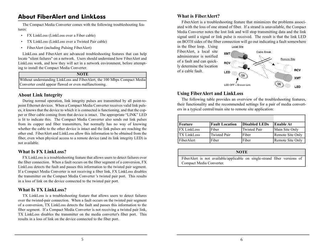
What is FiberAlert?FiberAlert is a troubleshooting feature that minimizes the problems associ-
ated with the loss of one strand of fiber. If a strand is unavailable, the CompactMedia Converter notes the lost link and will stop transmitting data and the linksignal until a signal or link pulse is received. The result is that the link LEDon BOTH sides of the fiber connection will go out indicating a fault somewherein the fiber loop. UsingFiberAlert, a local siteadministrator is notifiedof a fault and can quick-ly determine the locationof a cable fault.
Using FiberAlert and LinkLossThe following table provides an overview of the troubleshooting features,
their functionality and the recommended settings for a pair of media convert-ers in a typical central/main site to remote site application:
NOTEWithout understanding LinkLoss and FiberAlert, the 100 Mbps Compact MediaConverter could appear flawed or even malfunctioning.
Feature Fault Location Disabled LEDs Enable AtFX LinkLoss Fiber Twisted Pair Main Site OnlyTX LinkLoss Twisted Pair Fiber Remote Site OnlyFiberAlert Fiber Fiber Remote Site Only
NOTEFiberAlert is not available/applicable on single-strand fiber versions of Compact Media Converter.