100-002 Engine Diagrams - JustAnswer | Ask a Question, Get
20
100-002 Engine Diagrams Engine Views The following illustrations contain information about engine components, filter locations, drain points, and access locations for instrumentation and engine controls. The information and configuration of components shown in these illustrations are of a general nature. Some component locations will vary, depending on applications and installations. Automotive with CM570 Left View - CM570 ECM cooling plate 1. ECM 2. Compressor air inlet 3. Blowby measurement 4. Ambient air pressure sensor 5. Fuel return to tank 6. Engine dataplate 7. Engine serial number 8. Starter 9. Flywheel ring gear sensor 10. Side oil drain 11. Engine Diagrams http://127.0.0.1:7000/[email protected]/qs2/pubsys2/xml/e... 1 of 20 07/11/2010 22:54
Transcript of 100-002 Engine Diagrams - JustAnswer | Ask a Question, Get
100-002 Engine Diagrams
Engine Views
The following illustrations contain information about engine components, filter locations, drainpoints, and access locations for instrumentation and engine controls. The information andconfiguration of components shown in these illustrations are of a general nature. Somecomponent locations will vary, depending on applications and installations.
Automotive with CM570
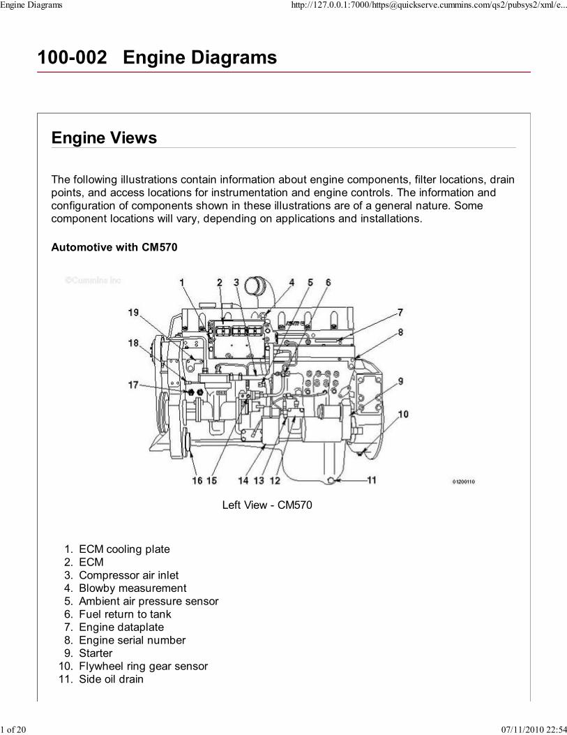
Left View - CM570
ECM cooling plate1.ECM2.Compressor air inlet3.Blowby measurement4.Ambient air pressure sensor5.Fuel return to tank6.Engine dataplate7.Engine serial number8.Starter9.Flywheel ring gear sensor10.Side oil drain11.
Engine Diagrams http://127.0.0.1:7000/[email protected]/qs2/pubsys2/xml/e...
1 of 20 07/11/2010 22:54
Centinel™ (optional)12.Fuel inlet to pump13.Fuel filter14.Rail pressure15.Power steering pump mounting location16.Oil pressure and temperature sensor17.Engine position sensor18.Refrigerant compressor mounting location.19.
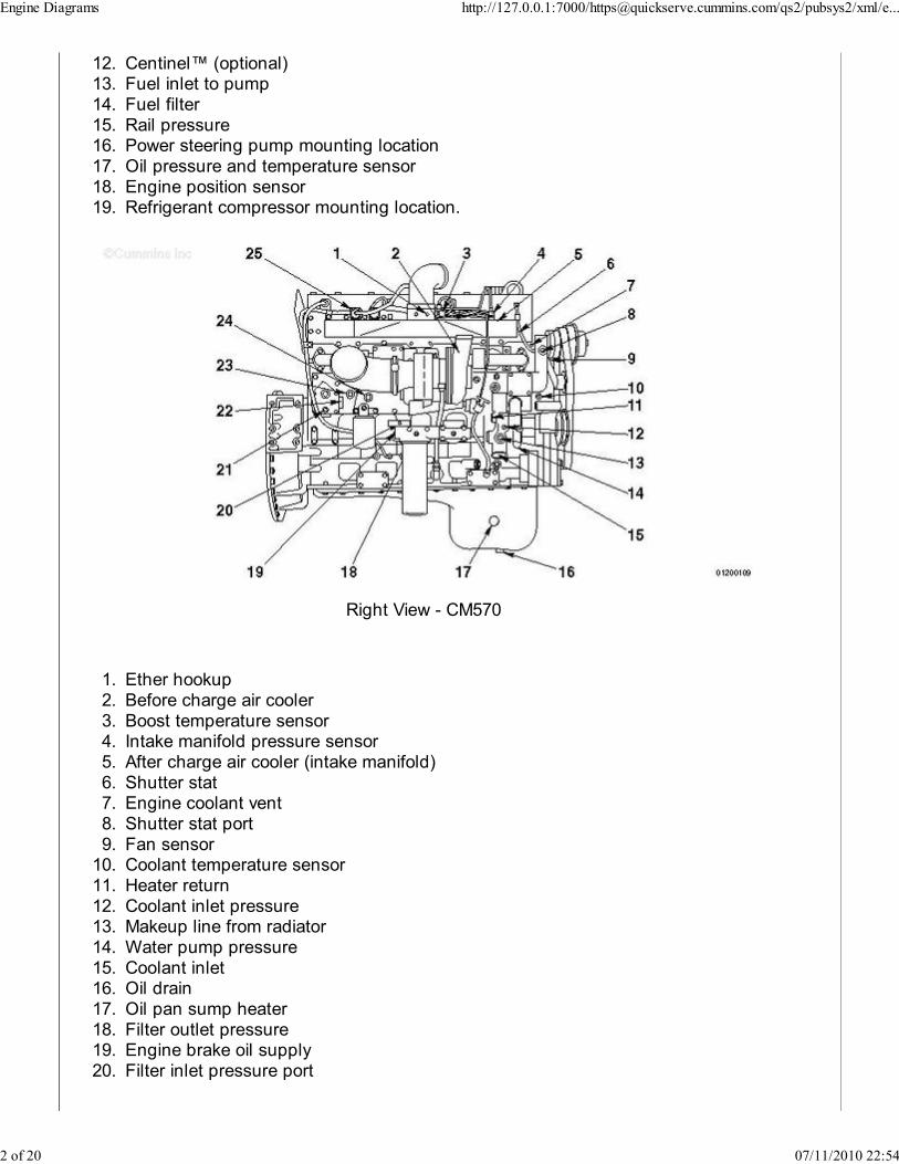
Right View - CM570
Ether hookup1.Before charge air cooler2.Boost temperature sensor3.Intake manifold pressure sensor4.After charge air cooler (intake manifold)5.Shutter stat6.Engine coolant vent7.Shutter stat port8.Fan sensor9.Coolant temperature sensor10.Heater return11.Coolant inlet pressure12.Makeup line from radiator13.Water pump pressure14.Coolant inlet15.Oil drain16.Oil pan sump heater17.Filter outlet pressure18.Engine brake oil supply19.Filter inlet pressure port20.
Engine Diagrams http://127.0.0.1:7000/[email protected]/qs2/pubsys2/xml/e...
2 of 20 07/11/2010 22:54
Block coolant pressure port21.Coolant heater port22.Heater supply port23.Coolant temperature pickup port24.Wastegate controller.25.
With CM870
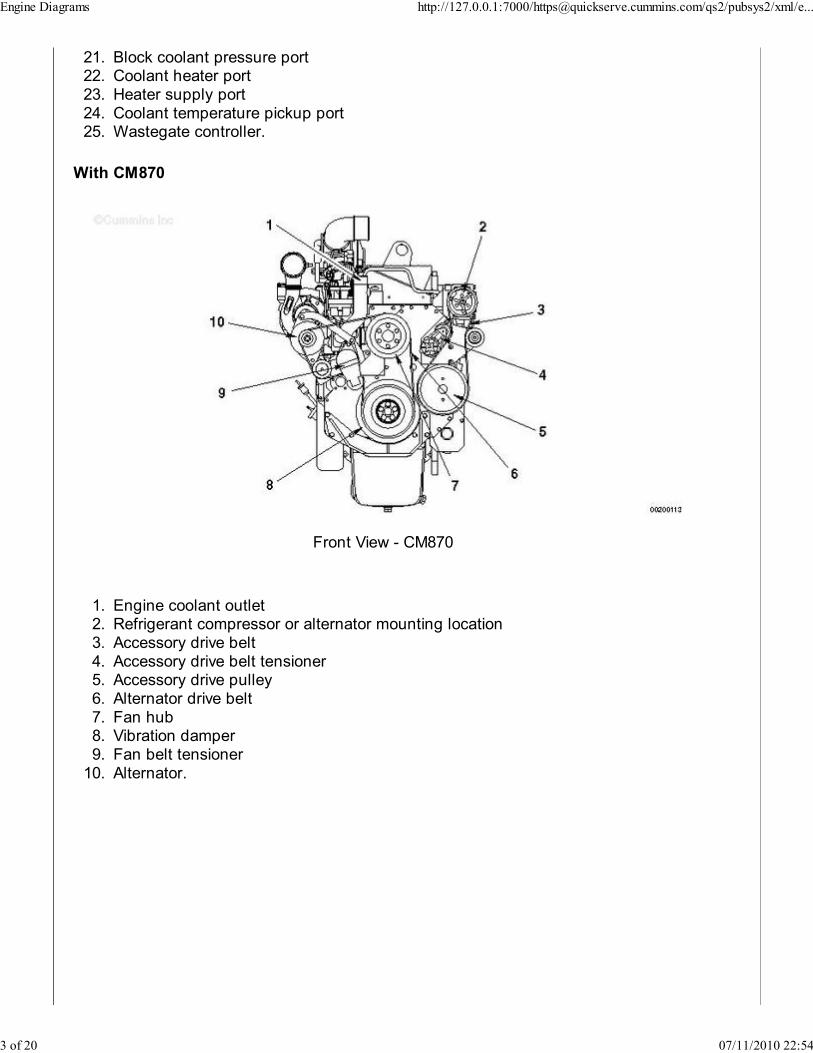
Front View - CM870
Engine coolant outlet1.Refrigerant compressor or alternator mounting location2.Accessory drive belt3.Accessory drive belt tensioner4.Accessory drive pulley5.Alternator drive belt6.Fan hub7.Vibration damper8.Fan belt tensioner9.Alternator.10.
Engine Diagrams http://127.0.0.1:7000/[email protected]/qs2/pubsys2/xml/e...
3 of 20 07/11/2010 22:54
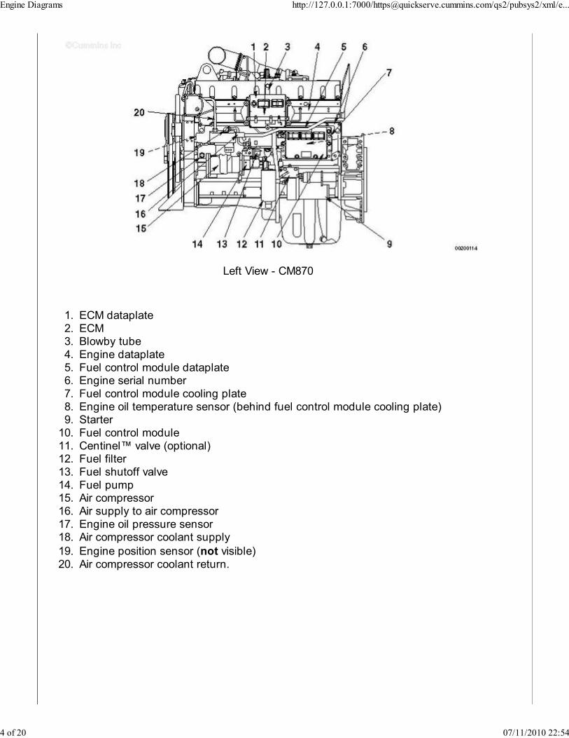
Left View - CM870
ECM dataplate1.ECM2.Blowby tube3.Engine dataplate4.Fuel control module dataplate5.Engine serial number6.Fuel control module cooling plate7.Engine oil temperature sensor (behind fuel control module cooling plate)8.Starter9.Fuel control module10.Centinel™ valve (optional)11.Fuel filter12.Fuel shutoff valve13.Fuel pump14.Air compressor15.Air supply to air compressor16.Engine oil pressure sensor17.Air compressor coolant supply18.
Engine position sensor (not visible)19.Air compressor coolant return.20.
Engine Diagrams http://127.0.0.1:7000/[email protected]/qs2/pubsys2/xml/e...
4 of 20 07/11/2010 22:54
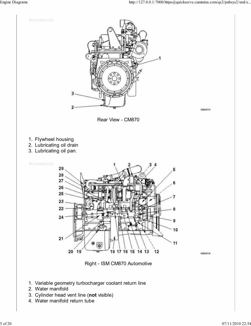
Rear View - CM870
Flywheel housing1.Lubricating oil drain2.Lubricating oil pan.3.
Right - ISM CM870 Automotive
Variable geometry turbocharger coolant return line1.Water manifold2.
Cylinder head vent line (not visible)3.Water manifold return tube4.
Engine Diagrams http://127.0.0.1:7000/[email protected]/qs2/pubsys2/xml/e...
5 of 20 07/11/2010 22:54
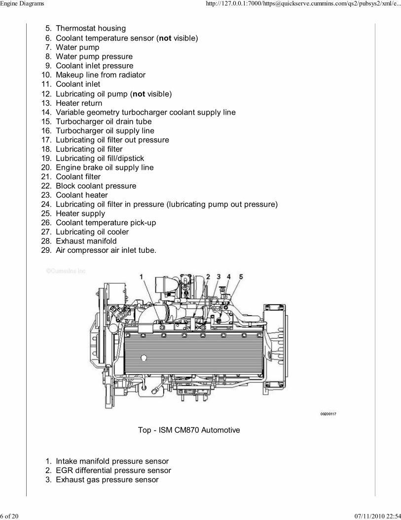
Thermostat housing5.
Coolant temperature sensor (not visible)6.Water pump7.Water pump pressure8.Coolant inlet pressure9.Makeup line from radiator10.Coolant inlet11.
Lubricating oil pump (not visible)12.Heater return13.Variable geometry turbocharger coolant supply line14.Turbocharger oil drain tube15.Turbocharger oil supply line16.Lubricating oil filter out pressure17.Lubricating oil filter18.Lubricating oil fill/dipstick19.Engine brake oil supply line20.Coolant filter21.Block coolant pressure22.Coolant heater23.Lubricating oil filter in pressure (lubricating pump out pressure)24.Heater supply25.Coolant temperature pick-up26.Lubricating oil cooler27.Exhaust manifold28.Air compressor air inlet tube.29.
Top - ISM CM870 Automotive
Intake manifold pressure sensor1.EGR differential pressure sensor2.Exhaust gas pressure sensor3.
Engine Diagrams http://127.0.0.1:7000/[email protected]/qs2/pubsys2/xml/e...
6 of 20 07/11/2010 22:54
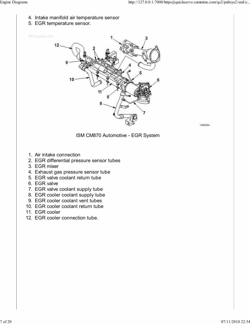
Intake manifold air temperature sensor4.EGR temperature sensor.5.
ISM CM870 Automotive - EGR System
Air intake connection1.EGR differential pressure sensor tubes2.EGR mixer3.Exhaust gas pressure sensor tube4.EGR valve coolant return tube5.EGR valve6.EGR valve coolant supply tube7.EGR cooler coolant supply tube8.EGR cooler coolant vent tubes9.EGR cooler coolant return tube10.EGR cooler11.EGR cooler connection tube.12.
Engine Diagrams http://127.0.0.1:7000/[email protected]/qs2/pubsys2/xml/e...
7 of 20 07/11/2010 22:54
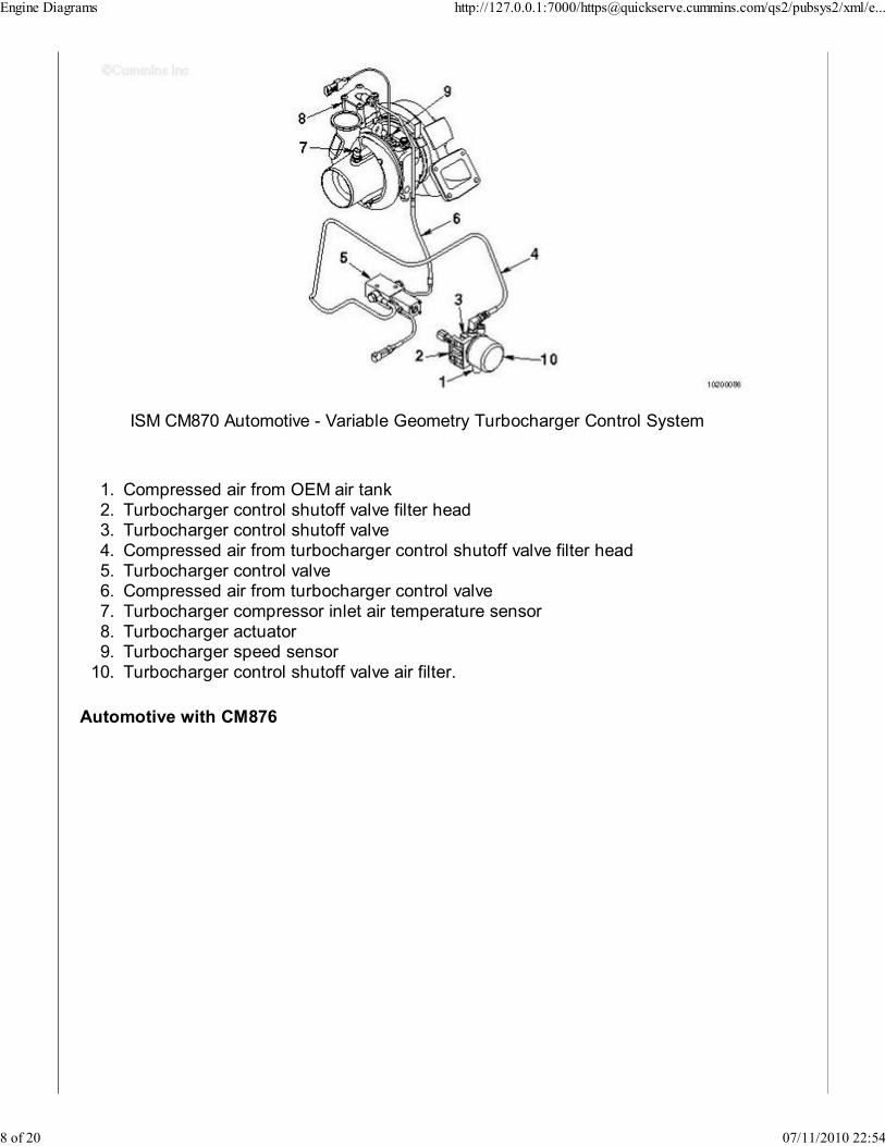
ISM CM870 Automotive - Variable Geometry Turbocharger Control System
Compressed air from OEM air tank1.Turbocharger control shutoff valve filter head2.Turbocharger control shutoff valve3.Compressed air from turbocharger control shutoff valve filter head4.Turbocharger control valve5.Compressed air from turbocharger control valve6.Turbocharger compressor inlet air temperature sensor7.Turbocharger actuator8.Turbocharger speed sensor9.Turbocharger control shutoff valve air filter.10.
Automotive with CM876
Engine Diagrams http://127.0.0.1:7000/[email protected]/qs2/pubsys2/xml/e...
8 of 20 07/11/2010 22:54
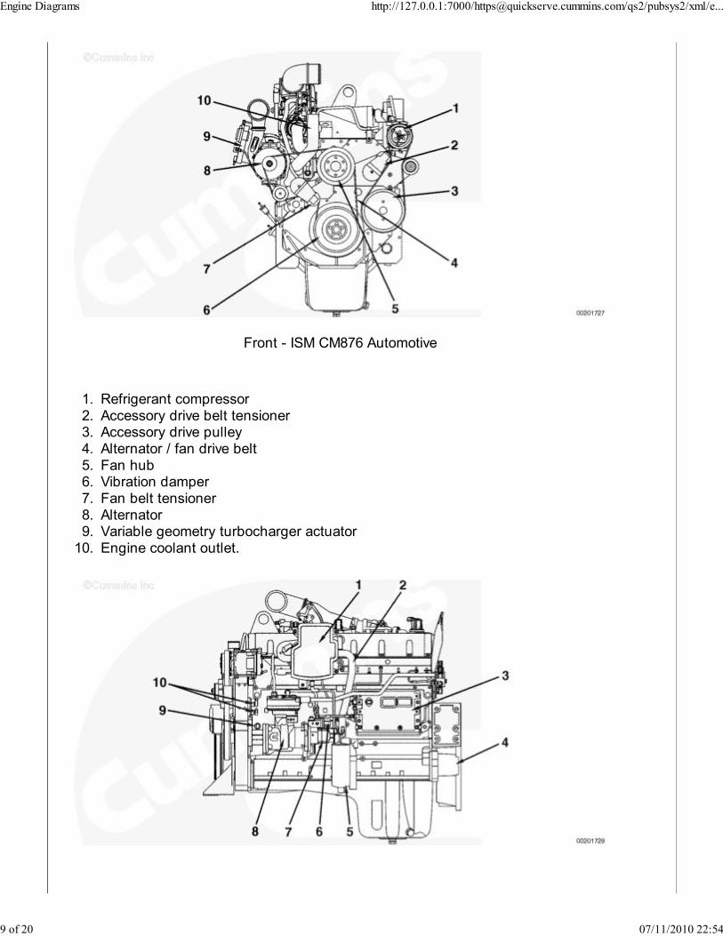
Front - ISM CM876 Automotive
Refrigerant compressor1.Accessory drive belt tensioner2.Accessory drive pulley3.Alternator / fan drive belt4.Fan hub5.Vibration damper6.Fan belt tensioner7.Alternator8.Variable geometry turbocharger actuator9.Engine coolant outlet.10.
Engine Diagrams http://127.0.0.1:7000/[email protected]/qs2/pubsys2/xml/e...
9 of 20 07/11/2010 22:54

Left - ISM CM876 Automotive
Open crankcase ventilation filter1.Blowby tube2.ECM3.Flywheel housing4.Fuel filter5.Fuel shutoff valve6.Fuel pump7.Air compressor8.Oil pressure sensor9.Engine position sensors.10.
Rear - ISM CM876
EGR valve1.Variable geometry turbocharger electronic actuator2.Variable geometry turbocharger3.Aftertreatment injector assembly4.Aftertreatment injector manifold5.Aftertreatment fuel pressure sensor6.Aftertreatment fuel shutoff valve7.Open crankcase ventilation filter.8.
Engine Diagrams http://127.0.0.1:7000/[email protected]/qs2/pubsys2/xml/e...
10 of 20 07/11/2010 22:54
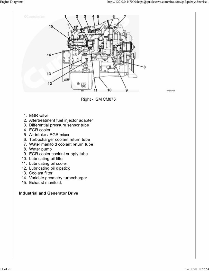
Right - ISM CM876
EGR valve1.Aftertreatment fuel injector adapter2.Differential pressure sensor tube3.EGR cooler4.Air intake / EGR mixer5.Turbocharger coolant return tube6.Water manifold coolant return tube7.Water pump8.EGR cooler coolant supply tube9.Lubricating oil filter10.Lubricating oil cooler11.Lubricating oil dipstick12.Coolant filter13.Variable geometry turbocharger14.Exhaust manifold.15.
Industrial and Generator Drive
Engine Diagrams http://127.0.0.1:7000/[email protected]/qs2/pubsys2/xml/e...
11 of 20 07/11/2010 22:54
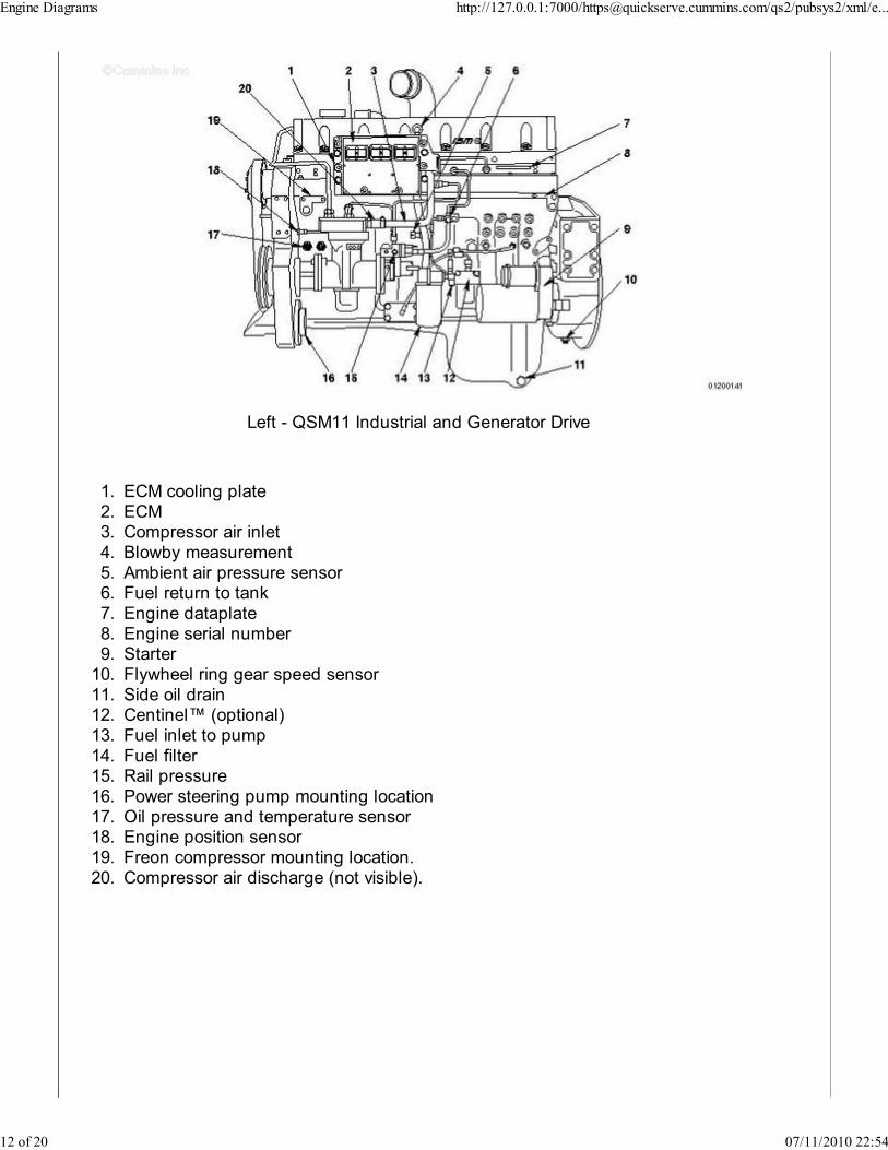
Left - QSM11 Industrial and Generator Drive
ECM cooling plate1.ECM2.Compressor air inlet3.Blowby measurement4.Ambient air pressure sensor5.Fuel return to tank6.Engine dataplate7.Engine serial number8.Starter9.Flywheel ring gear speed sensor10.Side oil drain11.Centinel™ (optional)12.Fuel inlet to pump13.Fuel filter14.Rail pressure15.Power steering pump mounting location16.Oil pressure and temperature sensor17.Engine position sensor18.Freon compressor mounting location.19.Compressor air discharge (not visible).20.
Engine Diagrams http://127.0.0.1:7000/[email protected]/qs2/pubsys2/xml/e...
12 of 20 07/11/2010 22:54
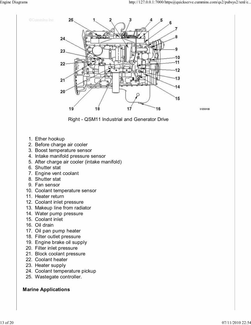
Right - QSM11 Industrial and Generator Drive
Ether hookup1.Before charge air cooler2.Boost temperature sensor3.Intake manifold pressure sensor4.After charge air cooler (intake manifold)5.Shutter stat6.Engine vent coolant7.Shutter stat8.Fan sensor9.Coolant temperature sensor10.Heater return11.Coolant inlet pressure12.Makeup line from radiator13.Water pump pressure14.Coolant inlet15.Oil drain16.Oil pan pump heater17.Filter outlet pressure18.Engine brake oil supply19.Filter inlet pressure20.Block coolant pressure21.Coolant heater22.Heater supply23.Coolant temperature pickup24.Wastegate controller.25.
Marine Applications
Engine Diagrams http://127.0.0.1:7000/[email protected]/qs2/pubsys2/xml/e...
13 of 20 07/11/2010 22:54
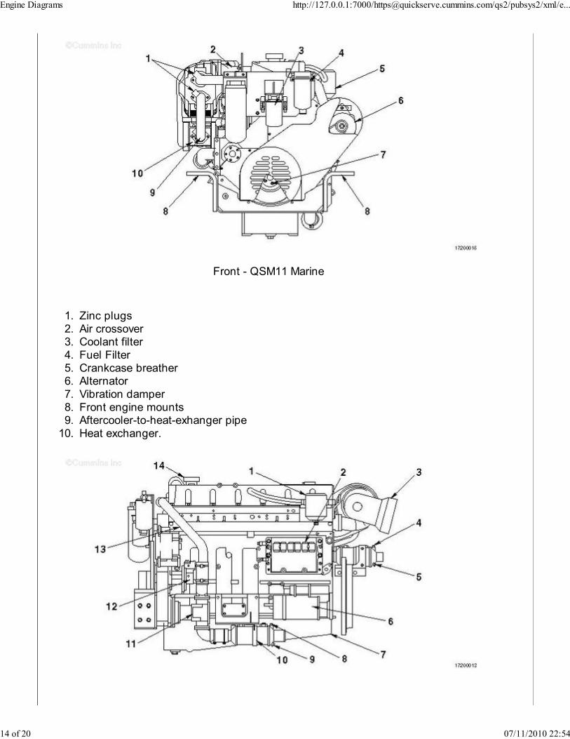
Front - QSM11 Marine
Zinc plugs1.Air crossover2.Coolant filter3.Fuel Filter4.Crankcase breather5.Alternator6.Vibration damper7.Front engine mounts8.Aftercooler-to-heat-exhanger pipe9.Heat exchanger.10.
Engine Diagrams http://127.0.0.1:7000/[email protected]/qs2/pubsys2/xml/e...
14 of 20 07/11/2010 22:54
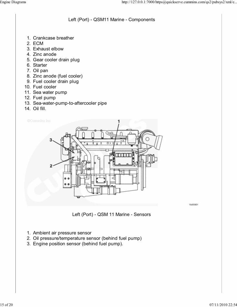
Left (Port) - QSM11 Marine - Components
Crankcase breather1.ECM2.Exhaust elbow3.Zinc anode4.Gear cooler drain plug5.Starter6.Oil pan7.Zinc anode (fuel cooler)8.Fuel cooler drain plug9.Fuel cooler10.Sea water pump11.Fuel pump12.Sea-water-pump-to-aftercooler pipe13.Oil fill.14.
Left (Port) - QSM 11 Marine - Sensors
Ambient air pressure sensor1.Oil pressure/temperature sensor (behind fuel pump)2.Engine position sensor (behind fuel pump).3.
Engine Diagrams http://127.0.0.1:7000/[email protected]/qs2/pubsys2/xml/e...
15 of 20 07/11/2010 22:54
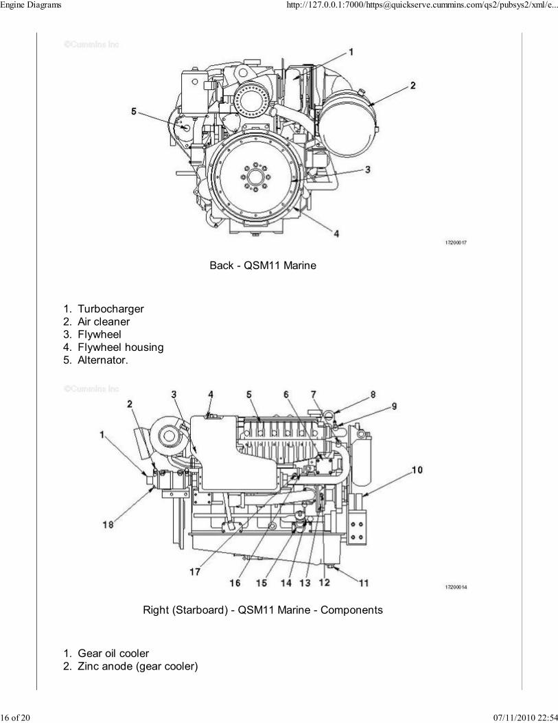
Back - QSM11 Marine
Turbocharger1.Air cleaner2.Flywheel3.Flywheel housing4.Alternator.5.
Right (Starboard) - QSM11 Marine - Components
Gear oil cooler1.Zinc anode (gear cooler)2.
Engine Diagrams http://127.0.0.1:7000/[email protected]/qs2/pubsys2/xml/e...
16 of 20 07/11/2010 22:54
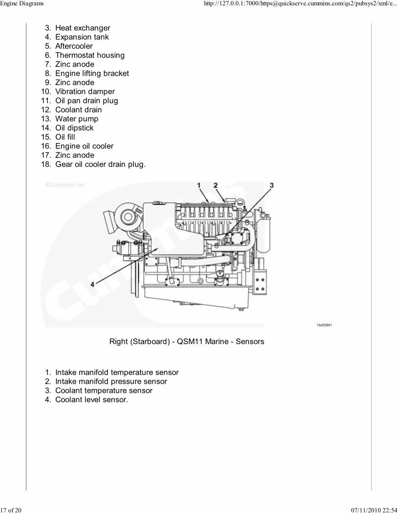
Heat exchanger3.Expansion tank4.Aftercooler5.Thermostat housing6.Zinc anode7.Engine lifting bracket8.Zinc anode9.Vibration damper10.Oil pan drain plug11.Coolant drain12.Water pump13.Oil dipstick14.Oil fill15.Engine oil cooler16.Zinc anode17.Gear oil cooler drain plug.18.
Right (Starboard) - QSM11 Marine - Sensors
Intake manifold temperature sensor1.Intake manifold pressure sensor2.Coolant temperature sensor3.Coolant level sensor.4.
Engine Diagrams http://127.0.0.1:7000/[email protected]/qs2/pubsys2/xml/e...
17 of 20 07/11/2010 22:54
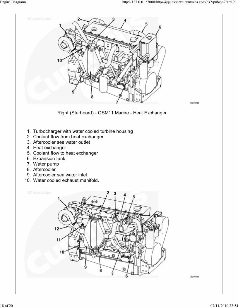
Right (Starboard) - QSM11 Marine - Heat Exchanger
Turbocharger with water cooled turbine housing1.Coolant flow from heat exchanger2.Aftercooler sea water outlet3.Heat exchanger4.Coolant flow to heat exchanger5.Expansion tank6.Water pump7.Aftercooler8.Aftercooler sea water inlet9.Water cooled exhaust manifold.10.
Engine Diagrams http://127.0.0.1:7000/[email protected]/qs2/pubsys2/xml/e...
18 of 20 07/11/2010 22:54
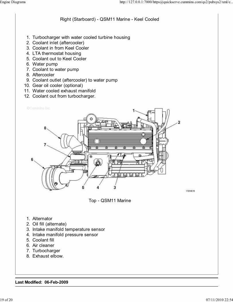
Right (Starboard) - QSM11 Marine - Keel Cooled
Turbocharger with water cooled turbine housing1.Coolant inlet (aftercooler)2.Coolant in from Keel Cooler3.LTA thermostat housing4.Coolant out to Keel Cooler5.Water pump6.Coolant to water pump7.Aftercooler8.Coolant outlet (aftercooler) to water pump9.Gear oil cooler (optional)10.Water cooled exhaust manifold11.Coolant out from turbocharger.12.
Top - QSM11 Marine
Alternator1.Oil fill (alternate)2.Intake manifold temperature sensor3.Intake manifold pressure sensor4.Coolant fill5.Air cleaner6.Turbocharger7.Exhaust elbow.8.
Last Modified: 06-Feb-2009
Engine Diagrams http://127.0.0.1:7000/[email protected]/qs2/pubsys2/xml/e...
19 of 20 07/11/2010 22:54

Copyright © 2000-2010 Cummins Inc. All rights reserved.
Engine Diagrams http://127.0.0.1:7000/[email protected]/qs2/pubsys2/xml/e...
20 of 20 07/11/2010 22:54