10. Topology discovery and protection - IEEE-SA - Working...
74
IEEE Draft P802.17/D2.2 RESILIENT PACKET RING (RPR) April 9, 2003 Copyright © 2002, 2003 IEEE. All rights reserved. This is an unapproved IEEE Standards Draft, subject to change. 233 1 2 3 4 5 6 7 8 9 10 11 12 13 14 15 16 17 18 19 20 21 22 23 24 25 26 27 28 29 30 31 32 33 34 35 36 37 38 39 40 41 42 43 44 45 46 47 48 49 50 51 52 53 54 10. Topology discovery and protection 10.1 Scope This clause describes the RPR topology discovery and protection functions, which include the topology discovery protocol, the protection protocol, and the type length value (TLV) attribute discovery protocol. The topology discovery and protection protocol enables the fundamental RPR objectives of sub-50 millisecond resiliency and automatic, plug-and-play topology discovery. In addition, the rapid detection of topology changes is required to ensure that strict data frames can be delivered with no re-ordering or duplication. The TLV discovery protocol enables additional, less time-critical information to be reported by each station to the rest of the ring. The protection protocol provides reliable mechanisms for sub-50 ms protection switching for all protected traffic on an RPR ring. It enables a mandatory protection mechanism called steering, and an optional protection mechanism called wrapping. This protocol ensures that each station receives link status change information, e.g., link failure or restoration information, required to make protection switching decisions reliably, and in the timeframe required. This protocol also ensures that stations steer or wrap in accordance Editors’ Notes: To be removed prior to final publication. References: None. Definitions: None Abbreviations: None. Revision History: Draft 0.3, June 2002 Initial draft document for RPR WG review. Editorial notes added for clarification. Draft 1.0, August 2002 Addressed comments from D0.3. Draft 1.1, October 2002 Addressed comments from D1.0. Draft 2.0, December 2002 Addressed comments from D1.1. Draft 2.1, February 2003 Draft 2.1 for WG review, modified according to comments on D2.0. Draft 2.2, April 2003 Draft 2.2 for WG ballot, modified according to comments on D2.1. Topology discovery and protection clauses combined. Editors’ Notes: To be removed prior to final publication. The protection ad-hoc (PAH) is meeting to address the following list of issues: 1. Comment #691, #704, #21017: Generate and review state machine description for modification and validation of the topology database, including duplicate MAC address checks. 2. Comment #21017, March: Determine how to handle passthrough mode, including how to achieve fast topology discovery for passthrough when there are TP frames left on the ring from stations that have disappeared from the ring is an issue that must be resolved. 3. Comment #728, #758, #21011, March: Determine how to handle context containment. 4. Comment #764, March: Simplify protection state machine while maintaining the same behavior. 5. Comment #739, March: Is there a requirement for lockout?
Transcript of 10. Topology discovery and protection - IEEE-SA - Working...

IEEE Draft P802.17/D2.2RESILIENT PACKET RING (RPR) April 9, 2003
Copyright © 2002, 2003 IEEE. All rights reserved.This is an unapproved IEEE Standards Draft, subject to change. 233
123456789101112131415161718192021222324252627282930313233343536373839404142434445464748495051525354
10. Topology discovery and protection
10.1 Scope
This clause describes the RPR topology discovery and protection functions, which include the topologydiscovery protocol, the protection protocol, and the type length value (TLV) attribute discovery protocol.The topology discovery and protection protocol enables the fundamental RPR objectives of sub-50millisecond resiliency and automatic, plug-and-play topology discovery. In addition, the rapid detection oftopology changes is required to ensure that strict data frames can be delivered with no re-ordering orduplication. The TLV discovery protocol enables additional, less time-critical information to be reported byeach station to the rest of the ring.
The protection protocol provides reliable mechanisms for sub-50 ms protection switching for all protectedtraffic on an RPR ring. It enables a mandatory protection mechanism called steering, and an optionalprotection mechanism called wrapping. This protocol ensures that each station receives link status changeinformation, e.g., link failure or restoration information, required to make protection switching decisionsreliably, and in the timeframe required. This protocol also ensures that stations steer or wrap in accordance
Editors’ Notes: To be removed prior to final publication.
References:None.
Definitions:None
Abbreviations:None.
Revision History:Draft 0.3, June 2002 Initial draft document for RPR WG review. Editorial notes added
for clarification.Draft 1.0, August 2002 Addressed comments from D0.3.Draft 1.1, October 2002 Addressed comments from D1.0.Draft 2.0, December 2002 Addressed comments from D1.1.Draft 2.1, February 2003 Draft 2.1 for WG review, modified according to comments on D2.0.Draft 2.2, April 2003 Draft 2.2 for WG ballot, modified according to comments on D2.1.
Topology discovery and protection clauses combined.
Editors’ Notes: To be removed prior to final publication.
The protection ad-hoc (PAH) is meeting to address the following list of issues:
1. Comment #691, #704, #21017: Generate and review state machine description for modification andvalidation of the topology database, including duplicate MAC address checks.
2. Comment #21017, March: Determine how to handle passthrough mode, including how to achieve fasttopology discovery for passthrough when there are TP frames left on the ring from stations that havedisappeared from the ring is an issue that must be resolved.
3. Comment #728, #758, #21011, March: Determine how to handle context containment.
4. Comment #764, March: Simplify protection state machine while maintaining the same behavior.
5. Comment #739, March: Is there a requirement for lockout?

IEEE Draft P802.17/D2.2April 9, 2003 DRAFT STANDARD FOR
Copyright © 2002, 2003 IEEE. All rights reserved.234 This is an unapproved IEEE Standards Draft, subject to change.
123456789
101112131415161718192021222324252627282930313233343536373839404142434445464748495051525354
with the RPR protection hierarchy. This protocol resides in the MAC control sublayer, as shown in theshaded region of Figure 10.1.
The topology discovery protocol provides a reliable and accurate means for all stations on a ring to discoverthe topology of the stations on the ring. This includes both the initial topology and any changes to thattopology. The topology discovery protocol also provides a mechanism for rapid detection of topologychanges. This protocol resides in the MAC control sublayer, as shown in the shaded region of Figure 10.1.
The topology discovery protocol is closely related to the protection protocol in that both share the samecontrol messaging mechanism. The information collected and used by both protocols is also logically storedtogether in a topology and status database. Information in the topology and status database is used by otherprotocols such as the RPR ringlet selection protocol, described in Clause 6, and the RPR fairness protocol,described in Clause 9.
The TLV discovery protocol provides a reliable and accurate means for all stations on a ring to discoveradditional, less time-critical information from the other stations on the ring. This protocol utilizes a distinctcontrol messaging mechanism. The information collected and used by the TLV discovery protocol is alsologically stored in the topology and status database.
All of these protocols are intended to be very scalable, to cause insignificant overhead for ring traffic, and tocause insignificant overhead on software and ASICs.
The services and features provided are:
a) Sub-50 ms protection switching for unicast and multicast traffic based on media “hard” or “soft”failures or based on operator invoked command.
b) Quick dissemination on the ring of information indicating media failures or operator invokedcommands impacting use of the media.
c) Support of a standard protection hierarchy.d) Greater bandwidth efficiency for unprotected services than path switching or bidirectional line
switching.
Figure 10.1—RPR layer diagram
RPR LAYERS
Higher layers
Medium
Presentation
Application
Session
Transport
Network
Data Link
Physical
OSIREFERENCE
MODELLAYERS
MAC datapath
Physical layer
Logical link control
MAC controlOAM
Fairness
Protection
Topology
IEEE Draft P802.17/D2.2RESILIENT PACKET RING (RPR) April 9, 2003
Copyright © 2002, 2003 IEEE. All rights reserved.This is an unapproved IEEE Standards Draft, subject to change. 235
123456789101112131415161718192021222324252627282930313233343536373839404142434445464748495051525354
e) Support of revertive and non-revertive protection switching operational modes.f) Determination and validation of connectivity and ordering of stations on the ring.g) Assurance that all stations on the ring converge to a uniform and current image of the topology.h) Operation with all supported topologies: ring (closed loop), bus (broken ring or open loop), and
isolated station.i) Support of dynamic addition and removal of stations to/from the ring.j) Scalability from one to hundreds of stationsk) Tolerance of frame loss.l) Operation without any master station on the ring.m) Operation independently of and in the absence of any management systems.n) Validation of topology, including detection of mis-cabling between stations.o) Means of sharing additional information between stations.p) Support of the above services and features with insignificant overhead.
10.2 Overview
The RPR topology discovery protocol provides each station on the ring with knowledge of the number andarrangement of other stations on the ring. This collection of information is referred to as the topology image.Each station maintains its own local copy of the topology image for the entire ring in its topology database.Initially, the station’s topology image contains information only about itself. The information required tocreate the basic topology image (including, for example, hop counts per ringlet from the local station to allother stations on the ring) is derivable from the topology and protection (TP) frames received from eachstation on the ring. TP frames are RPR control frames.
The link status, wrap status, and protection preference information required by the RPR protection protocolis also reported in the received TP frames. This information is also stored in the topology database for eachstation on the ring. The TP frame is used for this purpose because it is sent at a fast (substantially sub-50millisecond) rate, as well as on triggers. A specification of the triggers for the initiation of topologydiscovery and the fast rate is provided in 10.9, along with a specification of the TP frame in 10.5. 10.4 alsocontains a description of the complete processing flow for received TP frames.
The protection protocol does not directly switch traffic on the data plane. Rather, it supplies essentialinformation to entities within the MAC that do, such as ringlet selection, or directly controls when wrappingoccurs. It utilizes link protection status information stored in the topology database to help determine ifprotection switching is required. It ensures that parameters such as hold-off time and wait to restore timespecified by the network operator translate into correct station behavior. It ensures the robust interaction ofoperator-initiated protection requests and protection requests triggered by physical layer and MAC layermonitoring, within the framework of the RPR protection hierarchy.
The complete topology image contains more information than just station identifiers and physicalconnectivity relationships. It also contains station preferences information for use in various parts of thisstandard, and may contain optional vendor-specific information. Station preferences information iscontained within the station TLV frame, while vendor-specific information is contained within the
Editors’ Notes: To be removed prior to final publication.
A complete discussion of topology discovery time will be added to the appropriate location in the clausewhen the mechanisms for topology discovery for passthrough scenarios are finalized.
Detecting mis-cabling (above) assumes static local assignment of ring IDs (as opposed to dynamicdiscovery). How the assignments are made is a local, non-standardized decision. This might need to bediscussed in the OAM clause.
IEEE Draft P802.17/D2.2April 9, 2003 DRAFT STANDARD FOR
Copyright © 2002, 2003 IEEE. All rights reserved.236 This is an unapproved IEEE Standards Draft, subject to change.
123456789
101112131415161718192021222324252627282930313233343536373839404142434445464748495051525354
vendor-specific TLV frame. TLV frames are RPR control frames. The information contained in the stationand vendor-specific TLV frames is not as time-critical as that contained in the TP frame. A specification ofthe TLV frames is provided in 10.10, along with rules for the transmission and reception of TLV frames in10.11.
The transmission of TP frames is initiated as needed and periodically. TLV frames are transmittedperiodically. If the topology image is stable, the periodic TP and TLV frame transmissions will not result inany change to the topology database. Each station maintains its own topology database and follows auniform set of rules for transmission and reception of TP frames and TLV frames. There is no master station.
The topology discovery protocol is robust for both fully connected bidirectional rings (loops) and forbidirectional rings in which edges are detected (chains). Edges are detected on spans through which datadoes not transit. For example, an edge exists at a station that is wrapping traffic. The complete definition ofan edge is given in 10.7.
This clause also defines the modification and verification of the topology image upon receipt of TP framesor TLV frames. Topology stability and self-consistency must be validated because a failure of thisverification is an indication of significant operational problems in the ring.
10.2.1 Initialization
At station initialization, the local topology image is initialized to contain only the local station and no links.Upon initialization, the station broadcasts TP frames on all ringlets following the TP frame transmissionrules in 10.9.1. The station continually listens for TP frames broadcast on the ring, and updates its topologydatabase upon receipt of TP frames from stations that are not contained in its topology database, or fromstations already existing in its topology database for which TP frame contents have changed. Topologyvalidation checks are executed to ensure that the topology becomes consistent within a period of timedefined in 10.8.
On initialization the station is also triggered to broadcast station TLV frames (and if used, vendor-specificTLV frames) on all ringlets. After this initial trigger, the station broadcasts the TLV frames periodically, asdefined in 10.11.1. Neighbor MAC address information contained in the station TLV frames is initialized toall 0’s.
10.2.2 Addition of a station
When a station is inserted into an existing ring, it initializes itself as described above. Its neighbors detect thestation as a new neighbor by receiving its TP frame with a ttl set to MAX_STATIONS (indicating the framehas traveled exactly one hop) and with the source MAC address set to a value other than that previouslystored (if any).
The neighbor stations detect a new station on the ring, and respond by broadcasting a TP frame immediatelyon all ringlets. All other stations detect the new station by receiving its TP frame, and each responds bybroadcasting a TP frame immediately on all ringlets. The information available from the TP frame includesthe MAC address of the source station, the number of hops away the station is on the ringlet on which theframe is received (derived from ttl), and additional protection-related and time-sensitive station capabilitiesinformation described in 10.4.
All stations on the ring broadcast the TLV frames on all ringlets, and thus to all stations, based on theperiodic timer at each local station. TLV frames are not triggered except by the periodic timer. Each TLVframe is partitioned into Type-Length-Value (TLV) entries, as defined in 10.10.3.
IEEE Draft P802.17/D2.2RESILIENT PACKET RING (RPR) April 9, 2003
Copyright © 2002, 2003 IEEE. All rights reserved.This is an unapproved IEEE Standards Draft, subject to change. 237
123456789101112131415161718192021222324252627282930313233343536373839404142434445464748495051525354
When one or more stations come out of passthrough mode, those stations behave as newly initializedstations. The behavior of the other stations on the ring is identical to that for stations detecting a newlyinitialized station on the ring.
10.2.3 Removal of a station
When a station is removed from a ring, the neighbor stations detecting the removal of the station take theprotection actions described in 10.2.4. The neighbor stations detect a signal fail (SF) condition, and respondby broadcasting a TP frame immediately on all ringlets. All other stations detect this information byreceiving the TP frames. The information available from the TP frame includes the MAC address of thesource station, the number of hops away the station is on the ringlet on which the frame is received (derivedfrom ttl), and additional protection-related and time-sensitive station capabilities information described in10.4.
All stations on the ring broadcast the TLV frames on all ringlets, and thus to all stations, based on theperiodic timer at each local station. TLV frames are not triggered except by the periodic timer. Each TLVframe is partitioned into Type-Length-Value (TLV) entries, as defined in 10.10.3.
When one or more stations go into passthrough mode, those stations disappear from the ring both from acontrol and data perspective. The stations adjacent to one or more stations that have gone into passthroughcontinue periodic transmissions of the TP frame. The first station that receives a TP frame from a differentneighbor station than it saw previously is the first station to detect the passthrough event.
There is no objective or requirement to handle passthrough events in a 50 millisecond timeframe. 50millisecond protection switching and service restoration is only applicable to media failures, e.g., ring andstation failures resulting from a broken ring or a operator commanded protection event. The speed ofpassthrough detection currently depends on the setting of the TP frame transmission period.
10.2.4 Protection event on span
A protection switching protocol that provides the services and features described in 10.1 must define:
a) A hierarchy of protection requests that requires local action by a station and reporting of theprotection state to the rest of the ring. 10.6.2 includes description of the protection hierarchy, and ofthe definition of triggers resulting in specific protection requests.
b) The local actions that can be taken by stations on the ring to prevent traffic loss. As described in therest of this subclause, these consist of steering or wrapping. The choice between steering andwrapping is dictated by the algorithm described in 10.6.1.
Editors’ Notes: To be removed prior to final publication.
The rules for determining a valid topology for passthrough scenarios when there are TP frames left on thering from stations that have disappeared from the ring is an issue that will be resolved by the contributionto expand the contents of the topology validation subclause, 10.8.
Editors’ Notes: To be removed prior to final publication.
There is a distinction between fast detection of passthrough and fast rediscovery of topology after apassthrough event that removes one or more stations from the ring. To discover passthrough quickly, acontrol messaging function is required between neighbor stations, and that control message needs to besent periodically with a small period. To rediscover topology quickly after a passthrough event requires thetriggering of broadcast TP frame transmissions by every station on the ring in response to detection of apassthrough event. The fast rediscovery of topology is not a requirement.
IEEE Draft P802.17/D2.2April 9, 2003 DRAFT STANDARD FOR
Copyright © 2002, 2003 IEEE. All rights reserved.238 This is an unapproved IEEE Standards Draft, subject to change.
123456789
101112131415161718192021222324252627282930313233343536373839404142434445464748495051525354
c) A mechanism and control frame format for reporting local protection state to the rest of the ring.This is done using the TP frame.
d) State machine and related requirements. These are given in 10.6. The state machine defines in detailwhat protection state information is reported to the rest of the ring, exactly when it is reported, andexactly when action is taken at a station to protect traffic.
When a span fails, the stations detecting the failure store the knowledge of their neighbor station address onthe failed interface and clear their current knowledge of their neighbor station address on that interface. Thestations send TP frames that report exactly which links failed to the other stations on the ring.
10.2.4.1 Steering protection
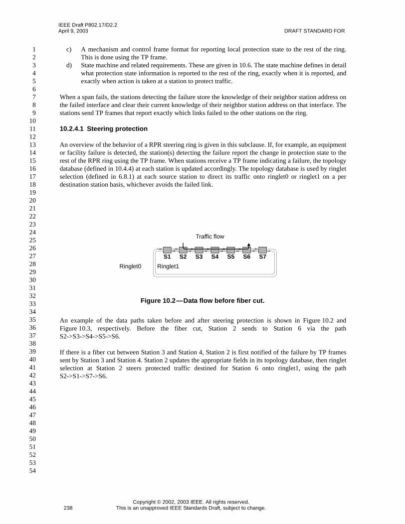
An overview of the behavior of a RPR steering ring is given in this subclause. If, for example, an equipmentor facility failure is detected, the station(s) detecting the failure report the change in protection state to therest of the RPR ring using the TP frame. When stations receive a TP frame indicating a failure, the topologydatabase (defined in 10.4.4) at each station is updated accordingly. The topology database is used by ringletselection (defined in 6.8.1) at each source station to direct its traffic onto ringlet0 or ringlet1 on a perdestination station basis, whichever avoids the failed link.
An example of the data paths taken before and after steering protection is shown in Figure 10.2 andFigure 10.3, respectively. Before the fiber cut, Station 2 sends to Station 6 via the pathS2->S3->S4->S5->S6.
If there is a fiber cut between Station 3 and Station 4, Station 2 is first notified of the failure by TP framessent by Station 3 and Station 4. Station 2 updates the appropriate fields in its topology database, then ringletselection at Station 2 steers protected traffic destined for Station 6 onto ringlet1, using the pathS2->S1->S7->S6.
Figure 10.2—Data flow before fiber cut.
S1 S2 S3 S4 S5 S6 S7
Traffic flow
Ringlet0 Ringlet1

IEEE Draft P802.17/D2.2RESILIENT PACKET RING (RPR) April 9, 2003
Copyright © 2002, 2003 IEEE. All rights reserved.This is an unapproved IEEE Standards Draft, subject to change. 239
123456789101112131415161718192021222324252627282930313233343536373839404142434445464748495051525354
Frames destined to a station beyond the point of failure that have been transmitted onto the ring before thesteering database is updated at the source station are dropped at the failure point, since there is no deliverymechanism available.
For steering rings, when a link fails, multicast frames are sent in both directions, with the ttl set to thenumber of stations on the ring between the source station and the defective span on each direction. Duplicatestrict mode frames must not be allowed to arrive at any station on the ring as a result of a protectioncondition ceasing to exist.
10.2.4.2 Wrap protection
An overview of the behavior of a RPR wrapping ring is given in this subclause. If an equipment or facilityfailure is detected, traffic going towards the failure is wrapped (looped) back to go in the opposite directionon the other ringlet (subject to the protection hierarchy). Wrapping takes place on the stations adjacent to thefailure, under control of the protection switch protocol. The wrap re-routes the traffic away from the failure.
An example of the data paths taken before and after a wrap is shown in Figure 10.4 and Figure 10.5,respectively. Before the fiber cut, Station 2 sends to Station 6 via the path S2->S3->S4->S5->S6.
Figure 10.3—Data path after steering protection
S1 S2 S3 S4 S5 S6 S7Traffic flow
Ringlet0 Ringlet1
Fiber cut
Figure 10.4—Data flow before fiber cut.
S1 S2 S3 S4 S5 S6 S7
Traffic flow
Ringlet0 Ringlet1
IEEE Draft P802.17/D2.2April 9, 2003 DRAFT STANDARD FOR
Copyright © 2002, 2003 IEEE. All rights reserved.240 This is an unapproved IEEE Standards Draft, subject to change.
123456789
101112131415161718192021222324252627282930313233343536373839404142434445464748495051525354
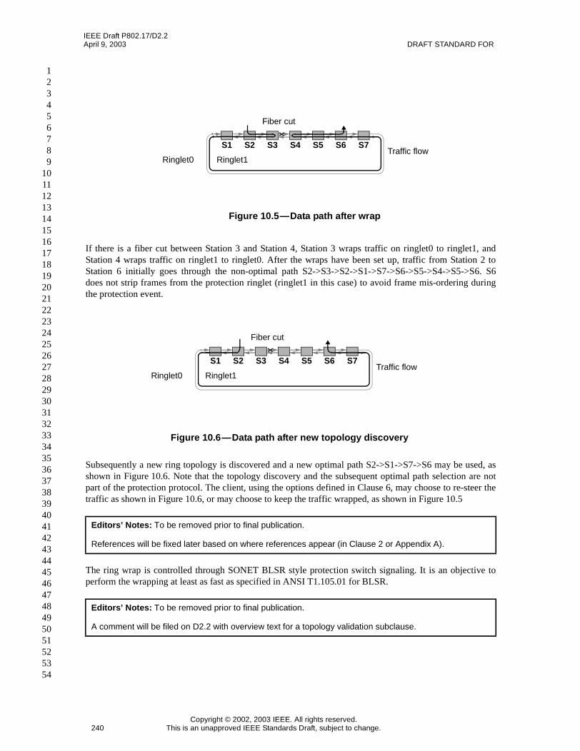
If there is a fiber cut between Station 3 and Station 4, Station 3 wraps traffic on ringlet0 to ringlet1, andStation 4 wraps traffic on ringlet1 to ringlet0. After the wraps have been set up, traffic from Station 2 toStation 6 initially goes through the non-optimal path S2->S3->S2->S1->S7->S6->S5->S4->S5->S6. S6does not strip frames from the protection ringlet (ringlet1 in this case) to avoid frame mis-ordering duringthe protection event.
Subsequently a new ring topology is discovered and a new optimal path S2->S1->S7->S6 may be used, asshown in Figure 10.6. Note that the topology discovery and the subsequent optimal path selection are notpart of the protection protocol. The client, using the options defined in Clause 6, may choose to re-steer thetraffic as shown in Figure 10.6, or may choose to keep the traffic wrapped, as shown in Figure 10.5
The ring wrap is controlled through SONET BLSR style protection switch signaling. It is an objective toperform the wrapping at least as fast as specified in ANSI T1.105.01 for BLSR.
Editors’ Notes: To be removed prior to final publication.
References will be fixed later based on where references appear (in Clause 2 or Appendix A).
Editors’ Notes: To be removed prior to final publication.
A comment will be filed on D2.2 with overview text for a topology validation subclause.
Figure 10.5—Data path after wrap
S1 S2 S3 S4 S5 S6 S7Traffic flow
Ringlet0 Ringlet1
Fiber cut
Figure 10.6—Data path after new topology discovery
S1 S2 S3 S4 S5 S6 S7Traffic flow
Ringlet0 Ringlet1
Fiber cut

IEEE Draft P802.17/D2.2RESILIENT PACKET RING (RPR) April 9, 2003
Copyright © 2002, 2003 IEEE. All rights reserved.This is an unapproved IEEE Standards Draft, subject to change. 241
123456789101112131415161718192021222324252627282930313233343536373839404142434445464748495051525354
10.3 Variables and terminology used
This clause defines the following terms and variables:
10.3.1 ringlet0Hops: Calculated. The number of downstream hops on ringlet0. This is equal to the totalnumber of stations on the ring in a loop topology, and is equal to the number of downstream hops until theedge span in a chain topology. This variable, along with ringlet1Hops, can be used to calculate the valueused to set the MIB attribute rprIfStationsOnRing.
10.3.2 ringlet1Hops: Calculated. The number of downstream hops on ringlet1. This is equal to the totalnumber of stations on the ring in a loop topology, and is equal to the number of downstream hops until theedge span in a chain topology. This variable, along with ringlet0Hops, can be used to calculate the valueused to set the MIB attribute rprIfStationsOnRing.
10.3.3 ringTopologyType: Calculated. The type of topology, with possible values LOOP or CHAIN. Themethod used to calculate this is described in 10.7. This is used by the data path module. The value of thisvariable is used to set the MIB attribute TBD.
10.3.4 eastFormerNeighborMACAddress: Calculated. The MAC address of the previously connectedneighbor station on the east span. When there is a neighbor station connected on the east span, the value ofthis variable is the MAC address of the current neighbor station on the east span. The value of this variableis used to set the MIB attribute TBD.
10.3.5 westFormerNeighborMACAddress: Calculated. The MAC address of the previously connectedneighbor station on the west span. When there is a neighbor station connected on the west span, the value ofthis variable is the MAC address of the current neighbor station on the west span. The value of this variableis used to set the MIB attribute TBD.
10.3.6 stationMACAddress: Calculated. The MAC address corresponding to a station entry in the logicaltopology database. There is one such entry for each station on the RPR ring. The value of this variable isused to set the MIB attribute rprTopoImageMacAddress.
Editors’ Notes: To be removed prior to final publication.
Proposed context containment scenarios will be posted for review before the May meeting. A comment willbe filed on D2.2 with description and scenarios to for an overview subclause on context containment.
Editors’ Notes: To be removed prior to final publication.
The following items are specified in the MIB but are not yet included in this clause:
rprSpanProtectionCountrprSpanProtectionDurationrprSpanProtectionLastActivationTime
It may also be useful to separately report the protection status information reported by the PHY and thatbased on MAC layer mechanisms (RPR keepalives) for diagnostic purposes.
Additional variables need to be specified to cover topology validation checks and failure conditions.
Some of the variables used in the protection state machine are not yet included in this list, since it isexpected that the protection state machine will be replaced in May with a modified, simpler state machine.

IEEE Draft P802.17/D2.2April 9, 2003 DRAFT STANDARD FOR
Copyright © 2002, 2003 IEEE. All rights reserved.242 This is an unapproved IEEE Standards Draft, subject to change.
123456789
101112131415161718192021222324252627282930313233343536373839404142434445464748495051525354
10.3.7 stationName: Calculated. The station name field within a station entry in the logical topologydatabase. There is one such entry for each station on the RPR ring. The value of this variable is used to setthe MIB attribute rprTopoImageStationName.
10.3.8 stationWrapPref: Configured. This is mapped to the value of the wp (wrap protection preferred) bit inthe TP frame sent by a station. The value of this variable is set by the MIB attribute rprIfWrapPreferred.
10.3.9 stationJumboPref: Configured. This is mapped to the value of the jp (jumbo frame preferred) bit inthe TP frame sent by a station. The value of this variable is set by the MIB attributerprIfJumboFramePreferred.
10.3.10 ringProtectionType: Calculated. The type of protection used on the ring. The method used to choosebetween steering and wrapping is described in 10.6.1. This is used by the data path module. The value of thisvariable is used to set the MIB attribute TBD.
10.3.11 ringJumboType: Calculated. The value of this variable indicates whether the ring supports receptionof jumbo frames. The method used to determine this is described in 10.6.1. The value of this variable is usedto set the MIB attribute TBD.
10.3.12 eastSideProtectionState: Calculated. The protection state on the east span within a station entry inthe logical topology database. There is one such entry for each station on the RPR ring. The value of thisvariable is used to set the MIB attribute rprTopoImageEastProtectionStatus.
10.3.13 westSideProtectionState: Calculated. The protection state on the west span within a station entry inthe logical topology database. There is one such entry for each station on the RPR ring. The value of thisvariable is used to set the MIB attribute rprTopoImageWestProtectionStatus.
10.3.14 eastSideEdgeStatus: Calculated. The edge status on the east span within a station entry in thelogical topology database. The edge status is the wrap status for a station on a wrapping ring, and is a spannot used for data transmission in a steering ring. There is one such entry for each station on the RPR ring.This is used by the data path module. The value of this variable is used to set the MIB attributerprTopoImageEastWrapStatus.
10.3.15 westSideEdgeStatus: Calculated. The edge status on the west span within a station entry in thelogical topology database. The edge status is the wrap status for a station on a wrapping ring, and is a spannot used for data transmission in a steering ring. There is one such entry for each station on the RPR ring.This is used by the data path module. The value of this variable is used to set the MIB attributerprTopoImageWestWrapStatus.
10.3.16 ringlet0Reachability: Calculated. The data reachability on ringlet0 from the local station to thestation corresponding to the station entry in the logical topology database. There is one such entry for eachstation on the RPR ring. The method used to calculate this is described in 10.7. The value of this variable isused to set the MIB attribute rprTopoImageRinglet0Reachability.
10.3.17 ringlet1Reachability: Calculated. The data reachability on ringlet1 from the local station to thestation corresponding to the station entry in the logical topology database. There is one such entry for eachstation on the RPR ring. The method used to calculate this is described in 10.7. The value of this variable isused to set the MIB attribute rprTopoImageRinglet1Reachability.
10.3.18 ringlet0Weight: Configured. This is mapped to the value of the ringlet0Weight field in the weightTLV in the station TLV frame sent by a station. The value of this variable is set by the MIB attributerprFairnessRingletWeight. rprTopoImageEastWeight.

IEEE Draft P802.17/D2.2RESILIENT PACKET RING (RPR) April 9, 2003
Copyright © 2002, 2003 IEEE. All rights reserved.This is an unapproved IEEE Standards Draft, subject to change. 243
123456789101112131415161718192021222324252627282930313233343536373839404142434445464748495051525354
10.3.19 ringlet1Weight: Configured. This is mapped to the value of the ringlet1Weight field in the weightTLV in the station TLV frame sent by a station. The value of this variable is set by the MIB attributerprFairnessRingletWeight. rprTopoImageWestWeight.
10.3.20 ringlet0ResBW: Configured. This is mapped to the value of the ringlet0ReservedBW field in thestation bandwidth TLV in the station TLV frame sent by a station. The value of this variable is set by theMIB attribute rprFairnessReservedRate. rprTopoImageRinglet0ReservedRate.
10.3.21 ringlet1ResBW: Configured. This is mapped to the value of the ringlet1ReservedBW field in thestation bandwidth TLV in the station TLV frame sent by a station. The value of this variable is set by theMIB attribute rprFairnessReservedRate. rprTopoImageRinglet1ReservedRate.
10.3.22 eastNeighborMACAddress: Calculated. The MAC address of the currently connected neighborstation on the east span as reported by the neighbor address TLV in the station TLV frame sent by a station.The value of this variable is used to set the MIB attribute TBD.
10.3.23 westNeighborMACAddress: Calculated. The MAC address of the currently connected neighborstation on the west span as reported by the neighbor address TLV in the station TLV frame sent by a station.The value of this variable is used to set the MIB attribute TBD.
10.3.24 localRequest: Configured. This is mapped to the value of localRequest used in the protection statemachine. The value of this variable is set by the MIB attribute rprSpanProtectionCommand.
10.3.25 IDLE: Value. This protection state corresponds to the MIB setting RprProtectionStatus, noRequest.
10.3.26 WTR: Value. This protection state corresponds to the MIB setting RprProtectionStatus,waitToRestore.
10.3.27 MS: Value. This protection state corresponds to the MIB setting RprProtectionStatus,manualSwitch.
10.3.28 SD: Value. This protection state corresponds to the MIB setting RprProtectionStatus,signalDegraded.
10.3.29 SF: Value. This protection state corresponds to the MIB setting RprProtectionStatus, signalFailed.
10.3.30 FS: Value. This protection state corresponds to the MIB setting RprProtectionStatus, forcedSwitch.
10.3.31 reversionMode: Configured. This defines whether a station is operating in revertive or non-revertivemode. This is mapped to the value of reversionMode used in the protection state machine. The value of thisvariable is set by the MIB attribute rprIfReversionMode.
10.3.32 wtrValue: Configured. This is mapped to the value of the WTR timer period. The value of thisvariable is set by the MIB attribute rprIfProtectionWTR.
10.3.33 fastTimerValue: Configured. This is mapped to the value of the fast timer period for TP messagetransmissions. The value of this variable is set by the MIB attribute rprIfProtectionFastTimer.
10.3.34 slowTimerValue: Configured. This is mapped to the value of the slow timer period for TP messagetransmissions. The value of this variable is set by the MIB attribute rprIfProtectionSlowTimer.
10.3.35 tlvTimerValue: Configured. This is mapped to the value of the timer period for TLV messagetransmissions. The value of this variable is set by the MIB attribute TBD.

IEEE Draft P802.17/D2.2April 9, 2003 DRAFT STANDARD FOR
Copyright © 2002, 2003 IEEE. All rights reserved.244 This is an unapproved IEEE Standards Draft, subject to change.
123456789
101112131415161718192021222324252627282930313233343536373839404142434445464748495051525354
10.3.36 holdoffTimerValue: Configured. This is mapped to the value of the holdoff timer period fordelaying the declaration of protection conditions. The value of this variable is set by the MIB attributerprSpanHoldOffTimer.
10.3.37 keepAliveTimeoutValue: Configured. This is mapped to the value of the keepalive timeout periodfor declaration of a MAC layer keepalive failure. The value of this variable is set by the MIB attributerprIfKeepaliveTimeout.
10.3.38 totalRinglet0ReservedBW: Calculated. The total reserved subclassA0 bandwidth on ringlet0. Themethod used to calculate this is described in 10.10.4.2. This is used by the fairness module, that needs thisinformation to determine the total reclaimable bandwidth in 9.3.15. The value of this variable is used to setthe MIB attribute TBD.
10.3.39 totalRinglet1ReservedBW: Calculated. The total reserved subclassA0 bandwidth on ringlet1. Themethod used to calculate this is described in 10.10.4.2. This is used by the fairness module, that needs thisinformation to determine the total reclaimable bandwidth in 9.3.15. The value of this variable is used to setthe MIB attribute TBD.
10.4 Flow chart for topology discovery and protection
A flow chart showing the overall flow of topology discovery and protection is shown in Figure 10.7. Thisflow chart represents the complete flow for a single station. The received frames mentioned in the flow chartare TP frames; the flow for TLV frames is described in 10.11. Detailed specification of the parts of this flowchart corresponding to normative state machines are given in various subclauses within Clause 10. Anoverview of the parts of this flow chart is given in the remainder of this subclause.
10.4.1 Local and external triggers
There is a protection state machine running on each side (east and west) of the local station.Protection-related events at the local station that cause entry to the protection state machine running on agiven side of the station (referred to as this side, with the other side referred to as the other side) include:
a) Local operator administrative request on this side of the station.b) Local operational failure on this receive interface of the station.c) Clearing of a local administrative request or operational failure on this receive interface of the
station.d) WTR timeout on this receive interface of the station.e) Administrative request or operational failure from the other interface of the station.
For example, for the protection state machine running on the west side of the station, this side refers to thewest side and the other side refers to the east side.
The criteria for setting administrative request conditions, setting operational failure conditions, and clearingeither type of condition are given in 10.6.2.
Editors’ Notes: To be removed prior to final publication.
When additional information is added to this clause on topology validation and context containment, thissubclause and the flow chart will be modified accordingly.

IEEE Draft P802.17/D2.2RESILIENT PACKET RING (RPR) April 9, 2003
Copyright © 2002, 2003 IEEE. All rights reserved.This is an unapproved IEEE Standards Draft, subject to change. 245
123456789101112131415161718192021222324252627282930313233343536373839404142434445464748495051525354
10.4.2 Receipt of topology and protection (TP) frames
Receipt of a TP frame from either ringlet first causes actions, including a sequence number check, describedin 10.9.2. If the check passes, both of the protection state machines (running on the east and west sides of thestation) are entered. The relevant information contained in the TP frame that is needed by the protectionstate machines is described in 10.9.2. If the check fails, the TP frame is discarded.
10.4.3 Protection state machine
The unified protection state machine for both steering and wrapping is defined in 10.6.3. There is oneprotection state machine running on each side of the station (east and west). The actions resulting from theprotection state machine running on a given side of the station include:
a) Setting of the wrap status bit for that side of the station. This is used later in the flow chart to cause astation to wrap receive traffic on that side of the station.
b) Determination of the protection state to be set into the link protection state fields of the topologydatabase for that receive interface of the station.
c) Determination of whether a TP frame is triggered due to a change in either the wrap status bit forthat side of the station, or due to a change in the protection state for that receive interface of thestation.
10.4.4 Topology database
There is a single central topology database that is modified based on the following:
a) Change in content of TP frames received from a particular station, or TP frame received from a newstation.
b) Change in content of TLV frames received from a particular station, or TLV frame received from anew station.
c) Change of the protection state or wrap status for either side of the local station.
The definition of the topology database and the state machine for modifying and validating it are given in10.4.4.

IEEE Draft P802.17/D2.2April 9, 2003 DRAFT STANDARD FOR
Copyright © 2002, 2003 IEEE. All rights reserved.246 This is an unapproved IEEE Standards Draft, subject to change.
123456789
101112131415161718192021222324252627282930313233343536373839404142434445464748495051525354
Figure 10.7—Flow chart for the protection protocol
Checksequencenumber is
latest
Discard theprotectionmessage
No
Enter East sideProtection state
machine
IstransmitProtect
ionMessagetrue
Transmitprotectionmessage
Yes
ProtectionMessage is
received fromringlet0 or ringlet1
Operator Requestor Local Failure orRequest from eastside, or change inprotection statefrom west side
Update TopologyDatabase
Is wrapStatusWest changed
Wrap or unwrapon west interfacebased on wrap
status bit
YesIs protectionmode wrapping
No
Yes
Wait for receivedprotection
message, operatorrequest or local
failure
No
No
Enter West sideProtection state
machine
Operator Requestor Local Failure orRequest from westside, or change inprotection statefrom east side
Yes
Is wrapStatusEast changed
Wrap or unwrapon east interfacebased on wrap
status bit
Yes
No

IEEE Draft P802.17/D2.2RESILIENT PACKET RING (RPR) April 9, 2003
Copyright © 2002, 2003 IEEE. All rights reserved.This is an unapproved IEEE Standards Draft, subject to change. 247
123456789101112131415161718192021222324252627282930313233343536373839404142434445464748495051525354
10.4.5 Triggering of TP frame transmission
The state machine defining the triggers for TP frame transmission is given in 10.9.1.
10.4.6 Wrapping/steering action
Based on the setting of the wrap status bit for each side of the station and whether a ring is a wrapping ring,a wrap or unwrap on each side of the station is triggered at this point in the flow chart. For steering, thetopology database has already been updated with modified link availability information, which provides thenecessary information for ringlet selection to perform steering, as defined in 6.8.1.
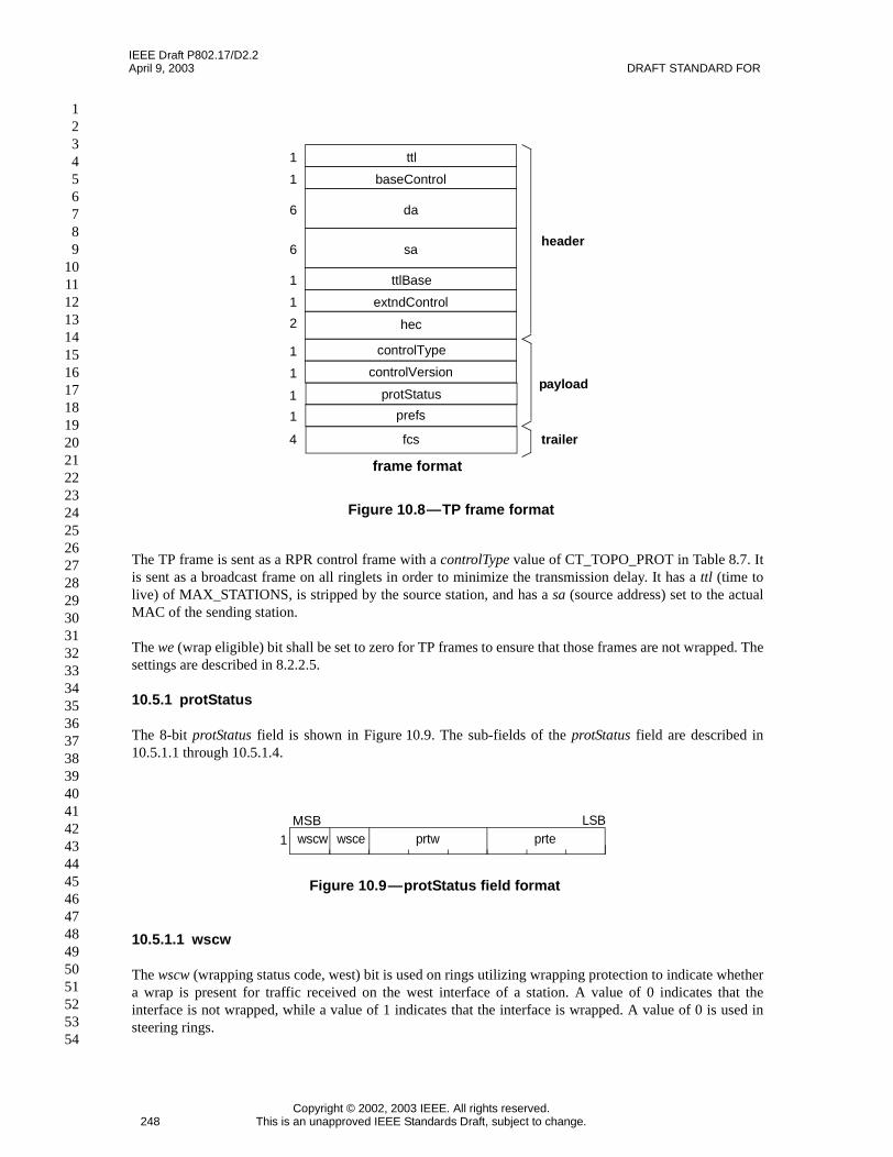
10.5 Topology and protection (TP) frame format
The TP frame is a fixed length frame. The TP frame is used for signaling link protection state (defined in10.6.2), for discovery of the physical topology of the ring, and for reporting of station preferencesinformation. The information reported in the TP frame is time critical.
The TP frame format is outlined in Figure 10.8.
The header portion of Figure 10.8 corresponds to the RPR header of the RPR control frame defined in 8.3.The controlVersion and controlType fields correspond to the fields with those names that are part of the RPRpayload of the RPR control frame.
Editors’ Notes: To be removed prior to final publication.
Flow chart will be modified to FrameMaker format in an upcoming version of the draft.
IEEE Draft P802.17/D2.2April 9, 2003 DRAFT STANDARD FOR
Copyright © 2002, 2003 IEEE. All rights reserved.248 This is an unapproved IEEE Standards Draft, subject to change.
123456789
101112131415161718192021222324252627282930313233343536373839404142434445464748495051525354
The TP frame is sent as a RPR control frame with a controlType value of CT_TOPO_PROT in Table 8.7. Itis sent as a broadcast frame on all ringlets in order to minimize the transmission delay. It has a ttl (time tolive) of MAX_STATIONS, is stripped by the source station, and has a sa (source address) set to the actualMAC of the sending station.
The we (wrap eligible) bit shall be set to zero for TP frames to ensure that those frames are not wrapped. Thesettings are described in 8.2.2.5.
10.5.1 protStatus
The 8-bit protStatus field is shown in Figure 10.9. The sub-fields of the protStatus field are described in10.5.1.1 through 10.5.1.4.
10.5.1.1 wscw
The wscw (wrapping status code, west) bit is used on rings utilizing wrapping protection to indicate whethera wrap is present for traffic received on the west interface of a station. A value of 0 indicates that theinterface is not wrapped, while a value of 1 indicates that the interface is wrapped. A value of 0 is used insteering rings.
Figure 10.8—TP frame format
1 baseControl
6 da
header
trailer
1 ttl
6 sa
1 extndControl
1 ttlBase
payload
2 hec
1 controlVersion
1 controlType
1 protStatus
1 prefs
4 fcs
frame format
Figure 10.9—protStatus field format
MSB LSB
1 wscw wsce prtw prte

IEEE Draft P802.17/D2.2RESILIENT PACKET RING (RPR) April 9, 2003
Copyright © 2002, 2003 IEEE. All rights reserved.This is an unapproved IEEE Standards Draft, subject to change. 249
123456789101112131415161718192021222324252627282930313233343536373839404142434445464748495051525354
10.5.1.2 wsce
The wsce (wrapping status code, east) bit is used on rings utilizing wrapping protection to indicate whether awrap is present for traffic received on the east interface of a station. A value of 0 indicates that the interfaceis not wrapped, while a value of 1 indicates that the interface is wrapped. A value of 0 is used in steeringrings.
10.5.1.3 prtw
The 3-bit prtw (protection request type, west) field is used to report the protection state on the west receiveinterface of a station.
The prtw values are defined in Table 10.1.
10.5.1.4 prte
The 3-bit prte (protection request type, east) field is used to report the protection state on the east receiveinterface of a station.
The prte values are defined in Table 10.1.
10.5.2 prefs
The 8-bit prefs field is shown in Figure 10.10. The sub-fields of the prefs field are described in 10.5.2.1through 10.5.2.3.
Table 10.1—prtw and prte values
Value (bin) Name Description
1112 — Reserved
1102 — Reserved
1012 PRT_FS Forced switch (FS)
1002 PRT_SF Signal fail (SF)
0112 PRT_SD Signal degrade (SD)
0102 PRT_MS Manual switch (MS)
0012 PRT_WTR Wait to restore (WTR)
0002 PRT_IDLE No request (IDLE)

IEEE Draft P802.17/D2.2April 9, 2003 DRAFT STANDARD FOR
Copyright © 2002, 2003 IEEE. All rights reserved.250 This is an unapproved IEEE Standards Draft, subject to change.
123456789
101112131415161718192021222324252627282930313233343536373839404142434445464748495051525354
10.5.2.1 wp
The wp (wrap protection preferred) bit is used to indicate if a station prefers wrap protection. The rules forthe selection of the protection mechanism to be used by an RPR ring is given in 10.6.1. A value of 0indicates that wrap protection is not preferred, while a value of 1 indicates that wrap protection is preferred.A value of 0 is used by steering stations, and by wrapping-capable stations that are configured to prefersteering. The variable stationWrapPref contains the operator configured value used to set this field.
The wp field is included in the TP frame to minimize frame loss for scenarios where a steering station isinserted into a wrapping ring (see Annex K). Since TP frames are stripped by stations receiving frames on awrapped span, the first TP frame sent by a newly inserted steering station is received by the neighboringstations (which are wrapped). Those stations immediately unwrap, but other stations on the ring do not findout that the ring has switched to steering mode until the next TP frame is transmitted by the steering station.To minimize frame loss, the wp field is included in the TP frame, which has the shortest fast transmissionperiod.
10.5.2.2 jp
The jp (jumbo frame preferred) bit is used to indicate if a station supports jumbo frames. The rule for thedetermination of whether an RPR ring supports jumbo frames is given in 10.6.1. A more detailed descriptionof what it means in RPR to support jumbo frames is given in 8.2. A value of 0 indicates that reception ofjumbo frames is not preferred, while a value of 1 indicates that reception of jumbo frames is preferred. Avalue of 0 is used by stations that are not capable of receiving jumbo frames, and by stations capable ofreceiving jumbo frames that are configured to prefer not to receive jumbo frames. The variablestationJumboPref contains the operator configured value used to set this field.
The jp field is included in the TP frame so that station preferences information is reported in a single frame.
10.5.2.3 seqnum
The 6-bit seqnum (sequence number) field that is incremented each time that the contents of a TP framechange, e.g., the same sequence number is used for the all copies of a given TP frame until its contentschange.
Figure 10.10—prefs field format
MSB LSB
1 wp jp seqnum

IEEE Draft P802.17/D2.2RESILIENT PACKET RING (RPR) April 9, 2003
Copyright © 2002, 2003 IEEE. All rights reserved.This is an unapproved IEEE Standards Draft, subject to change. 251
123456789101112131415161718192021222324252627282930313233343536373839404142434445464748495051525354
10.6 Protection protocol
10.6.1 Protection protocol rules
Fundamental protection rules in RPR include:
a) An RPR ring shall provide protection within 50ms of detection of a link or station failure.b) All RPR stations shall provide support for steering, with support for wrapping optional.c) All stations within the same RPR ring shall choose the same protection mechanism. Via the topology
discovery protocol, every RPR station shall indicate if it prefers wrapping protection or not based onthe configured local stationWrapPref setting. The indication in the TP frame is via the wp (wrapprotection preferred) field defined in 10.5.2.1. If and only if all stations on an RPR ring advertisewrapping as the preferred protection mechanism, the wrapping protection mechanism shall beautomatically used by all stations in the ring. Otherwise, steering shall be selected as the defaultprotection scheme on the RPR ring.
d) A jumbo frame preferred station in an RPR ring shall behave as a non jumbo frame preferred stationif any station on that ring reports that it is not jumbo frame preferred. This is via the jp (jumbo framepreferred) field defined in 10.5.2.2.
e) Revertive operation shall be the default mode of operation in RPR rings. Selection of revertive ornon-revertive mode is supported through configuration of reversionMode. The behavior ofnon-revertive mode is equivalent to the behavior for an infinite WTR time. The behavior of anon-revertive station in terms of reporting and clearing of WTR shall be fully consistent with allrules pertaining to WTR.
10.6.1.1 TP frame transfer mechanism
a) TP frames are transferred in a broadcast frame format between stations on the ring. A received frameis passed to the receiving station’s MAC control sublayer.
b) Triggering rules for TP frames are given in 10.9.1.c) TP frames shall continue to be delivered on links that are in non-idle protection states.
10.6.1.2 RPR protection signaling mechanism
a) Protection switch signaling is performed using TP frames as defined in Figure 10.8.b) A station transmits a TP frame on both ringlets. The definition of the transmission of TP frames is
given in 10.9.
10.6.1.3 Additional protection protocol rules
a) The protection request hierarchy values are listed in Table 10.1 (listed from highest priority tolowest priority). In general, a higher priority request preempts a lower priority request within thering, with exceptions noted as rules. The 3 bit values shown in the table correspond to the TP framerequest type (PMRT) field in the TP frame.
b) When a station which initially detected a failure discovers the disappearance of the failure, it entersWTR (for a user-configured WTR time period wtrValue). The configurable range for WTR isdefined in 10.6.2.
c) When a station is in WTR mode, and detects (via matching the MAC address of the new neighbor tothe former neighbor MAC address on that span stored in the topology database,eastFormerNeighborMACAddress or westFormerNeighborMACAddress) that a new neighbor is not
Editors’ Notes: To be removed prior to final publication.
The rules below need to be reformatted to conform with the IEEE editorial template and style.
IEEE Draft P802.17/D2.2April 9, 2003 DRAFT STANDARD FOR
Copyright © 2002, 2003 IEEE. All rights reserved.252 This is an unapproved IEEE Standards Draft, subject to change.
123456789
101112131415161718192021222324252627282930313233343536373839404142434445464748495051525354
the same as the old neighbor (stored while the old neighbor was still recognized as part of thetopology), the station drops the WTR. This is done to allow a new station just connected into a ringto become data reachable from other stations as quickly as possible. The information from thetopology database is needed so that protection knows when to apply WTR without requiringprotection to separately store topology information.
d) When a station receives a local protection request of type SD or SF and it cannot be executed(according to protocol rules), it keeps the request pending. (The request can be kept pending outsideof the protection protocol implementation.)
e) If a local non-failure request (WTR, MS, FS) clears, and if there are no other requests pending, thestation enters idle state.
f) If there are two link failures and two resulting WTR conditions on a single segment, the secondWTR to time out brings both the links up. (After a WTR time expires, a station does not unprotectautomatically, but waits until it receives idle frames from its neighbor on the previously failedsegment.)
g) The WTR on any link is dropped when a higher priority request is detected elsewhere on the ring.This requires the station monitoring the link with the WTR condition to check whether there arehigher priority requests elsewhere on the ring.
h) A configurable hold-off time holdoffTimerValue must be supported per side of the station forprotection triggers with a range of zero to at least 200 ms with 10 ms resolution. The default value iszero. The hold-off time is provided to prevent a spurious response to glitches on a link where suchglitches are expected. For example, this could occur due to protection switching of RPR traffic byunderlying SONET infrastructure.
i) An MS command on an interface of a station is rejected if there is another MS on the ring.j) In case of the failure of a station’s pass-through path (in Figure 6.4, between the ringlet0 datapath
and the wrapW mux, or between the ringlet1 datapath and the wrapE mux), a station shall not wrapon both sides. An example is if a station includes two separate hardware modules (East and West)which are interconnected and the interconnecting pass-through cable or circuitry fails. A centerwrapped station does not wrap on both sides because the two sides of the station would appear to beseparate stations with duplicate MAC addresses. Rather, a center wrapped station shall choose towrap on one of the two sides in case of failure in its pass-through path.
k) A TP frame shall be accepted only if the sequence number contained within the control header asdefined in 10.5 meets the conditions defined in 10.9.2.
l) Requests higher than or equal to SF in the protection hierarchy can coexist. All requests above SFneed to be cleared before the state is transferred into idle state.
m) Requests lower than SF in the protection hierarchy can not coexist with other requests. A higherpriority request preempts a lower priority request.
For wrapping, two different spans with SF conditions result in simultaneous wraps on both spans.The desired behavior for two or more different spans with SD conditions is that the affected spansare equally usable, and therefore no wraps shall result. If two or more SD conditions, or two or moreMS conditions, occur nearly simultaneously, then there may be a transient condition where there arewraps on some of the affected spans for a brief interval, but stations of these affected spans unwrapimmediately when they find out that there is more than one SD condition, or more than one MScondition, in the ring. There is no corresponding condition for steering, as ringlet selection for trafficentering a ring with two or more spans with SD conditions can be handled independently at eachsource station. In this case ringlet selection treats all SD conditions equally when determining whichdirection on the ring to send traffic.
n) If a short path FS request is present on a given segment, and a SF condition takes place on the samesegment, a station shall accept and process the SF condition ignoring the FS. (Without this rule, asingle ended wrap condition could take place, wrapping on only one end of a segment.)
When a steering-preferred station is inserted into a wrapping ring, the station will send out TP frames onboth ringlets indicating that it does not prefer wrapping. Its neighbor stations unwrap immediately uponfinding out that there is a station on the ring that does not prefer wrapping. Subsequent TP frames are

IEEE Draft P802.17/D2.2RESILIENT PACKET RING (RPR) April 9, 2003
Copyright © 2002, 2003 IEEE. All rights reserved.This is an unapproved IEEE Standards Draft, subject to change. 253
123456789101112131415161718192021222324252627282930313233343536373839404142434445464748495051525354
forwarded to the rest of the ring. Upon receipt of these frames, all other stations on the ring proceed to steertheir traffic.
When the only steering-preferred station is removed from a ring where all other stations prefer wrapping, itsneighbor stations wrap immediately. Upon receipt of TP frames from the neighbor stations (andmodification of the topology database) indicating that the only steering-preferred station has been removedfrom the ring, ringProtectionType is set to wrapping. This causes ringlet selection to steer traffic back to theoriginal default direction for each destination station.
10.6.2 Protection hierarchy and triggers
The protection switch protocol processes the following request types (in the order of priority, from highest tolowest). The triggers for these requests are defined below. All requests are signaled using TP frames definedin 10.5.
1) Forced Switch (FS): Operator originated. Results in a protection switch away from a requestedlink (steering or wrapping all traffic away from the link). An example use of this request type isto add another station to the ring in a controlled fashion.
2) Signal Fail (SF): Automatic. Caused by a media Signal Failure or RPR keepalive failure. Amedia SF shall be detected based on the PHY_LINK_STATUS.indication defined in 7.2.3.Results in a protection switch away from the impacted link (steering or wrapping all trafficaway from the link). SONET examples of SF triggers are: Loss of Signal (LOS), Loss of Frame(LOF), Line Bit Error Rate (BER) above a preselected SF threshold, and Line Alarm IndicationSignal (AIS). Explicit definition of the SF triggers and SF clearing criteria for SONET areprovided in the Telcordia GR-253-CORE and ANSI T1.105.01 standards, among others. AnRPR keepalive failure is defined later in this clause. The configurable hold-off timeholdoffTimerValue, if non-zero, starts after the physical SF condition is detected and shallelapse before SF triggers. Incorrect connection of interfaces of neighboring stations throughmiscabling shall also result in a MAC layer SF condition. Also, as described in Annex G, aninternal failure within a station, such as the failure of a station’s pass-through path, may beindicated as a SF condition on one side of the station to the rest of the ring.
3) Signal Degrade (SD): Automatic. Caused by a media Signal Degrade (e.g., excessive Bit ErrorRate). A media SD shall be detected based on the PHY_LINK_STATUS.indication defined in7.2.3. Results in a protection switch away from the impacted link (steering or wrapping alltraffic away from the link). SONET examples of SD triggers are: Line BER or Path BER abovea preselected SD threshold. Explicit definition of the SD triggers and SD clearing criteria forSONET are provided in the Telcordia GR-253-CORE and ANSI T1.105.01 standards, amongothers. The configurable hold-off time, if non-zero, starts after the physical SD condition isdetected and shall elapse before SD triggers.
4) Manual Switch (MS): Operator originated. Like Forced Switch but of a lower priority. Anexample use of this request type is to force down a marginally operating link, but allow it tocome back into use in the case of a more serious failure elsewhere on the ring.
5) Wait to Restore (WTR): Automatic. Entered after a link meets the restoration criteria followingexit from a SF or SD condition. The protection switch protocol waits for the WTR time-outbefore restoring traffic. An example use of this request type is to prevent protection switchoscillations. The configurable range for WTR is defined later in this clause.
The protection module finds out about operator originated protection requests and clearing from the LayerManagement Entity defined in Clause 12. It finds out about automatic protection requests via link statusprimitives defined in Annex B and Annex C for the Ethernet and SONET/SDH reconciliation sublayers,respectively. The protection module may also utilize automatic protection triggers mapped into SF or SD notexplicitly defined in Annex B and Annex C.

IEEE Draft P802.17/D2.2April 9, 2003 DRAFT STANDARD FOR
Copyright © 2002, 2003 IEEE. All rights reserved.254 This is an unapproved IEEE Standards Draft, subject to change.
123456789
101112131415161718192021222324252627282930313233343536373839404142434445464748495051525354
Table 10.2 shows the mapping of LINK_STATUS values from the PHY to actual MAC protection statevalues, taking into account the internal MAC status. The internal MAC status may be Idle or SF, where SF iscaused by an RPR keepalive failure or a ringlet identifier mismatch due to miscabling..
The purpose of RPR keepalives is to provide an indication that a station has an acceptable degree ofoperational capability. The transmission of RPR keepalives ideally should occur only if all implementedchecks of normal MAC operation are fulfilled.
An RPR keepalive failure on a receive span is defined by the failure to receive any SC-FCM frames (asdefined in Clause 9) for a configurable time range from 2 ms to 50 ms, with resolution 1 ms and a defaultvalue of 3 ms. This is set in keepAliveTimeoutValue. This means that to trigger an RPR keepalive failure, atleast four consecutive SC-FCM frames must be missed, based on the 400 microsecond largest advertisementinterval between SC-FCM frames.
A SF condition due to loss of keepalives is not cleared solely by the re-start of reception of keepalives froma newly connected or re-connected neighbor station. Upon receipt of a single keepalive, the link transitionsto WTR state. For a new neighbor, if a TP frame is received from the neighbor before the WTR expires, thelink is brought up upon receipt of the TP frame. If the WTR expires prior to receipt of a TP frame, then thelink is brought up based on WTR regardless of whether the neighbor is a new neighbor or unchanged frombefore the SF condition.
In a passthrough mode scenario, the SC-FCM frame will be forwarded through the station or stations inpassthrough. The detection of SF based on loss of keepalives is based on the same criteria at the receivestation as if there were no stations in passthrough. The clearing criteria are also the same as if there were nostations in passthrough.
An SF condition due to miscabling is triggered by a ringlet ID mismatch on a TP frame received from aneighboring station (ttl == MAX_STATIONS).
The application of WTR upon clearing of an SF condition due to miscabling is the same as for any other SFcondition. The SF condition is cleared by the receipt of a single TP frame received from a neighboringstation with the correct ringlet ID. WTR is then applied based on whether the MAC address of theneighboring station is the same as or different from the MAC address of the previously connectedneighboring station, as described in 10.6.1.
Table 10.2— Mapping of LINK_STATUS and internal MAC status to protection status
LINK_STATUSfrom PHY
Internal MACstatus MAC Protection Status
OK IDLE IDLE
SF SF
DEGRADE IDLE SD
SF SF
FAIL IDLE SF
SF SF
DEGRADE ANDFAIL
IDLE SF
SF SF
IEEE Draft P802.17/D2.2RESILIENT PACKET RING (RPR) April 9, 2003
Copyright © 2002, 2003 IEEE. All rights reserved.This is an unapproved IEEE Standards Draft, subject to change. 255
123456789101112131415161718192021222324252627282930313233343536373839404142434445464748495051525354
WTR shall be configured in wtrValue with values in the range of 0-1440 sec. with resolution of 1 second andwith a default value of 10 seconds.
The following applies for both steering and wrapping rings unless stated otherwise.
Link failure or degradation indications (SF or SD) are reported to the entire ring, independent of whetherthere is a higher priority request in existence on the ring. The purpose of this reporting is to enable eachstation to have as complete a picture as possible of the status of all links on the ring, which is beneficial froma diagnostic perspective. This reporting is independent of whether, for wrapping rings, wrapping is causedby link degradation indications. A wrap shall always be initiated based on SF. A wrap shall be initiatedbased on SD only if there is no equal or higher priority request elsewhere on the ring, as detailed in 10.6.1.
A forced switch (FS) indication always goes into effect (and causes a wrap in wrapping rings) and isreported to the entire ring, except in the case described in (to prevent a single-ended wrap). A manual switchshall go into effect only if there is no equal or higher priority request elsewhere on the ring, as detailed in10.6.1.
A wait to restore (WTR) is cleared immediately if a higher priority request is initiated from elsewhere on thering.
Protection requests from any station travel around the ring and are stored in the topology and status databaseat all stations on the ring. For steering rings, to determine which ringlet is preferred for the transmission offrames from a given source to a given destination, the highest protection request on each path connecting thesource and destination must be compared. For example, if there are links with protection request SD on theportion of ringlet0 connecting station A to station B, and there is a link with protection request SF on theportion of ringlet1 connecting station A to station B, then ringlet0 would be selected for steering traffic fromstation A to station B.
All protection switches are performed bidirectionally (protect at both ends of a segment for both transmitand receive directions, even if a failure is only unidirectional).
10.6.3 Protection state machine
This subclause specifies the unified state machine for both steering and wrapping protection, and somerelated requirements. As described in 10.6.3, there is a protection state machine running on each side (eastand west) of each station. State transitions that are specific to either steering or wrapping are noted withinthe state machine.
10.6.3.1 Inputs
localRequestAdministrative request on the interface on which the protection state machine is running.Values:FS: Forced switch.MS: Manual switch.
localFailureOperational failure on the interface on which the protection state machine is running.Values:SF: Signal fail.
Editors’ Notes: To be removed prior to final publication.
A contribution from the PAH to simplify the presentation of the protection state machine without modifyingbehavior will be submitted as a comment to D2.2, and will be posted for review before the May meeting.

IEEE Draft P802.17/D2.2April 9, 2003 DRAFT STANDARD FOR
Copyright © 2002, 2003 IEEE. All rights reserved.256 This is an unapproved IEEE Standards Draft, subject to change.
123456789
101112131415161718192021222324252627282930313233343536373839404142434445464748495051525354
SD: Signal degrade.rxMsg
Received TP frame (may be from any station on the ring other than the local station, and eitherringlet). Relevant fields are sa, ttl, ri, wscw, wsce, prtw, and prte, as defined in 10.5.
localRequestClearIndication that local request currently in effect has cleared.Values:TRUE: Local request has cleared.
eastSideProtectionStateValue of protection state reported from the other side of the station (for the protection statemachine running on the west side of the station, the other side is the east side).Values:FS: Forced switch.SF: Signal fail.SD: Signal degrade.MS: Manual switch.WTR: Wait to restore.IDLE: Idle.
westSidePendingReqClearIndication that the pending protection request on this side of the station has cleared (for theprotection state machine running on the west side of the station, this side is the west side).Values:TRUE: Pending request has cleared.
localFailureClearIndication that local failure condition currently in effect has cleared.Values:TRUE: Local failure has cleared.
wtrExpiredIndication that wait to restore time on this side of the station has expired (for the protection statemachine running on the west side of the station, this side is the west side).Values:TRUE: Wait to restore time has expired.
10.6.3.2 Constants
FSForced switch.
SFSignal fail.
SDSignal degrade.
MSManual switch.
WTRWait to restore.
IDLEIdle.
WSC_WRAPPEDWrap status bit set to 1 (wrapped).
WSC_IDLEWrap status bit set to 0 (not wrapped, or idle).

IEEE Draft P802.17/D2.2RESILIENT PACKET RING (RPR) April 9, 2003
Copyright © 2002, 2003 IEEE. All rights reserved.This is an unapproved IEEE Standards Draft, subject to change. 257
123456789101112131415161718192021222324252627282930313233343536373839404142434445464748495051525354
10.6.3.3 Variables
westSideProtectionStateProtection state of west side of station.
westSideProtStateChangeIndication that protection state of west side of station has changed. This will be an input to theprotection state machine running on the east side of the station.
transmitProtectionFrameIndication that TP frames need to be triggered. This is an input to the TP frame transmission statemachine defined in 10.9.1.
westSidePendingReqPending protection request on west side of station.
eastSideProtStateChangeIndication that protection state reported from the other side of the station has changed (for theprotection state machine running on the west side of the station, the other side is the east side).Values:TRUE: Protection state from the other side of the station has changed.FALSE: This variable has been cleared after eastSideProtectionState has been read in by theprotection state machine running on the west side of the station.
westNeighborMACAddressMAC address of station on the other end of the affected span (the short path neighbor as defined inFigure 10.15.
reversionModeReversion mode configured for the station.Values:TRUE: Station is revertive.FALSE: Station is non-revertive.
10.6.3.4 Functions
The functions below are used in the protection state diagram (or within functions used in the protection statediagram) presented later in this document.
AvoidSingleEndedWrapThe purpose of this function is to prevent an FS request on a span of a station from causing asingle-ended wrap. The FS request is rejected if the neighbor on the same span detects an SF on itsreceive link. This prevents situations where the clearing of the FS cannot be communicated to theneighbor station. In this function, neighborProtectionState for the protection state machine runningon the west side of the station corresponds to the eastSideProtectionState of the neighbor stationdetermined to be the “short path” neighbor as per Figure 10.15. neighborProtectionState for theprotection state machine running on the east side of the station corresponds to thewestSideProtectionState of the neighbor station determined to be the “short path” neighbor as perFigure 10.15.
AvoidSingleEndedWrap(REQ)!((REQ == FS) && (neighborProtectionState == SF))Values:TRUE: FS request is accepted on a span of a station.FALSE: FS request is rejected on a span of a station.
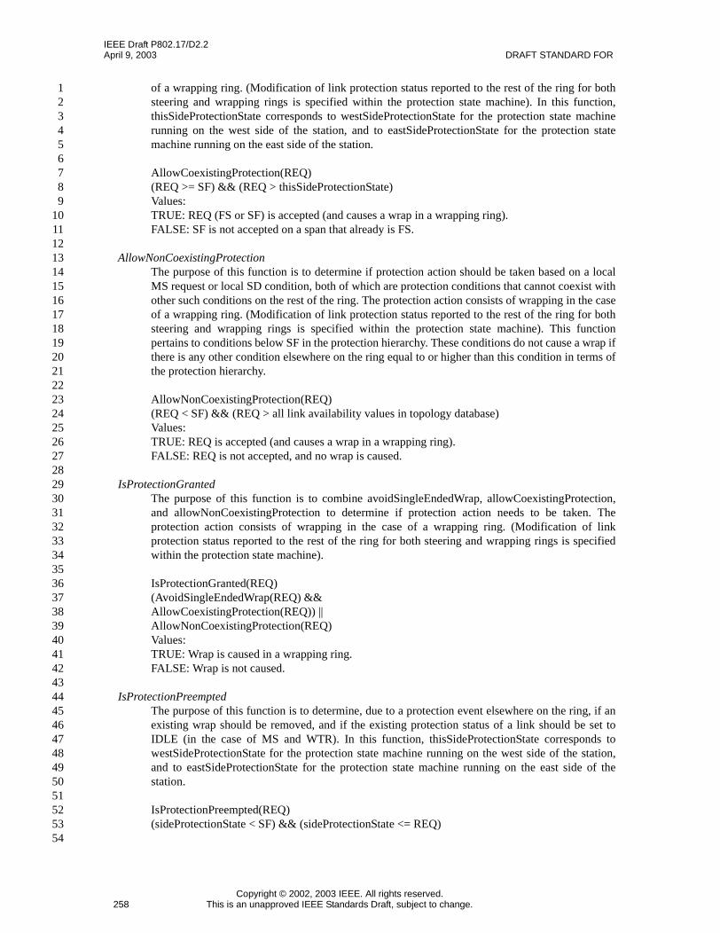
AllowCoexistingProtectionThe purpose of this function is to determine if protection action should be taken based on a localFS request or local SF condition, both of which are protection conditions that can coexist withother such conditions on the rest of the ring. The protection action consists of wrapping in the case
IEEE Draft P802.17/D2.2April 9, 2003 DRAFT STANDARD FOR
Copyright © 2002, 2003 IEEE. All rights reserved.258 This is an unapproved IEEE Standards Draft, subject to change.
123456789
101112131415161718192021222324252627282930313233343536373839404142434445464748495051525354
of a wrapping ring. (Modification of link protection status reported to the rest of the ring for bothsteering and wrapping rings is specified within the protection state machine). In this function,thisSideProtectionState corresponds to westSideProtectionState for the protection state machinerunning on the west side of the station, and to eastSideProtectionState for the protection statemachine running on the east side of the station.
AllowCoexistingProtection(REQ)(REQ >= SF) && (REQ > thisSideProtectionState)Values:TRUE: REQ (FS or SF) is accepted (and causes a wrap in a wrapping ring).FALSE: SF is not accepted on a span that already is FS.
AllowNonCoexistingProtectionThe purpose of this function is to determine if protection action should be taken based on a localMS request or local SD condition, both of which are protection conditions that cannot coexist withother such conditions on the rest of the ring. The protection action consists of wrapping in the caseof a wrapping ring. (Modification of link protection status reported to the rest of the ring for bothsteering and wrapping rings is specified within the protection state machine). This functionpertains to conditions below SF in the protection hierarchy. These conditions do not cause a wrap ifthere is any other condition elsewhere on the ring equal to or higher than this condition in terms ofthe protection hierarchy.
AllowNonCoexistingProtection(REQ)(REQ < SF) && (REQ > all link availability values in topology database)Values:TRUE: REQ is accepted (and causes a wrap in a wrapping ring).FALSE: REQ is not accepted, and no wrap is caused.
IsProtectionGrantedThe purpose of this function is to combine avoidSingleEndedWrap, allowCoexistingProtection,and allowNonCoexistingProtection to determine if protection action needs to be taken. Theprotection action consists of wrapping in the case of a wrapping ring. (Modification of linkprotection status reported to the rest of the ring for both steering and wrapping rings is specifiedwithin the protection state machine).
IsProtectionGranted(REQ)(AvoidSingleEndedWrap(REQ) &&AllowCoexistingProtection(REQ)) ||AllowNonCoexistingProtection(REQ)Values:TRUE: Wrap is caused in a wrapping ring.FALSE: Wrap is not caused.
IsProtectionPreemptedThe purpose of this function is to determine, due to a protection event elsewhere on the ring, if anexisting wrap should be removed, and if the existing protection status of a link should be set toIDLE (in the case of MS and WTR). In this function, thisSideProtectionState corresponds towestSideProtectionState for the protection state machine running on the west side of the station,and to eastSideProtectionState for the protection state machine running on the east side of thestation.
IsProtectionPreempted(REQ)(sideProtectionState < SF) && (sideProtectionState <= REQ)
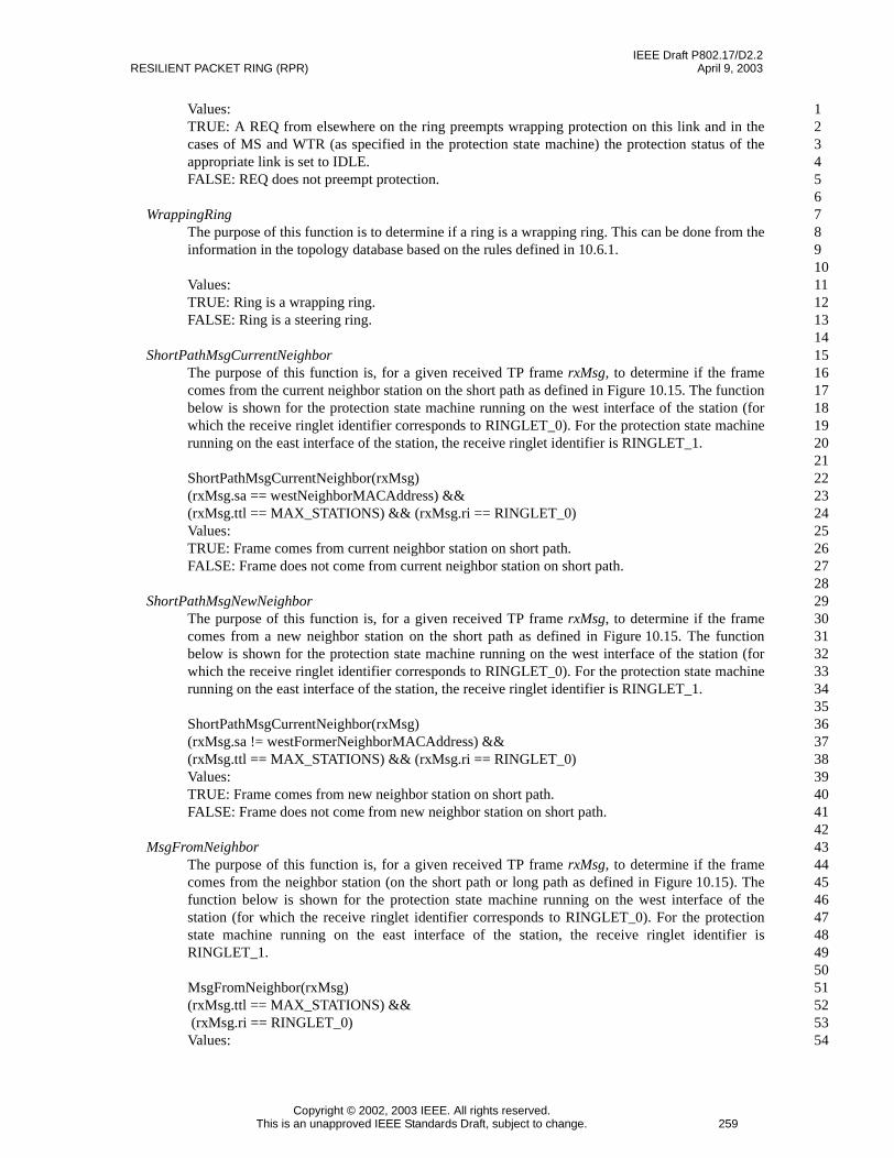
IEEE Draft P802.17/D2.2RESILIENT PACKET RING (RPR) April 9, 2003
Copyright © 2002, 2003 IEEE. All rights reserved.This is an unapproved IEEE Standards Draft, subject to change. 259
123456789101112131415161718192021222324252627282930313233343536373839404142434445464748495051525354
Values:TRUE: A REQ from elsewhere on the ring preempts wrapping protection on this link and in thecases of MS and WTR (as specified in the protection state machine) the protection status of theappropriate link is set to IDLE.FALSE: REQ does not preempt protection.
WrappingRingThe purpose of this function is to determine if a ring is a wrapping ring. This can be done from theinformation in the topology database based on the rules defined in 10.6.1.
Values:TRUE: Ring is a wrapping ring.FALSE: Ring is a steering ring.
ShortPathMsgCurrentNeighborThe purpose of this function is, for a given received TP frame rxMsg, to determine if the framecomes from the current neighbor station on the short path as defined in Figure 10.15. The functionbelow is shown for the protection state machine running on the west interface of the station (forwhich the receive ringlet identifier corresponds to RINGLET_0). For the protection state machinerunning on the east interface of the station, the receive ringlet identifier is RINGLET_1.
ShortPathMsgCurrentNeighbor(rxMsg)(rxMsg.sa == westNeighborMACAddress) &&(rxMsg.ttl == MAX_STATIONS) && (rxMsg.ri == RINGLET_0)Values:TRUE: Frame comes from current neighbor station on short path.FALSE: Frame does not come from current neighbor station on short path.
ShortPathMsgNewNeighborThe purpose of this function is, for a given received TP frame rxMsg, to determine if the framecomes from a new neighbor station on the short path as defined in Figure 10.15. The functionbelow is shown for the protection state machine running on the west interface of the station (forwhich the receive ringlet identifier corresponds to RINGLET_0). For the protection state machinerunning on the east interface of the station, the receive ringlet identifier is RINGLET_1.
ShortPathMsgCurrentNeighbor(rxMsg)(rxMsg.sa != westFormerNeighborMACAddress) &&(rxMsg.ttl == MAX_STATIONS) && (rxMsg.ri == RINGLET_0)Values:TRUE: Frame comes from new neighbor station on short path.FALSE: Frame does not come from new neighbor station on short path.
MsgFromNeighborThe purpose of this function is, for a given received TP frame rxMsg, to determine if the framecomes from the neighbor station (on the short path or long path as defined in Figure 10.15). Thefunction below is shown for the protection state machine running on the west interface of thestation (for which the receive ringlet identifier corresponds to RINGLET_0). For the protectionstate machine running on the east interface of the station, the receive ringlet identifier isRINGLET_1.
MsgFromNeighbor(rxMsg)(rxMsg.ttl == MAX_STATIONS) &&(rxMsg.ri == RINGLET_0)
Values:

IEEE Draft P802.17/D2.2April 9, 2003 DRAFT STANDARD FOR
Copyright © 2002, 2003 IEEE. All rights reserved.260 This is an unapproved IEEE Standards Draft, subject to change.
123456789
101112131415161718192021222324252627282930313233343536373839404142434445464748495051525354
TRUE: Frame comes from neighbor station.FALSE: Frame does not come from neighbor station.
10.6.3.5 Protection state table
The state machine in Table 10.3 shows the required conditions for the following types of protection actionsto be taken:
a) Setting of the wrap status bit for a span of the station. This is used later in the flow chart to cause astation to wrap.
b) Determination of the protection request value to be set into the link availability fields of thetopology database for each receive link of the station.
c) Determination of whether a TP frame is triggered due to a change in either the wrap status bit for aspan of the station, or due to a change in the protection request value for a receive link of the station.
The initial state is the START (IDLE) state. Optional rows are shaded in grey. In the case of any ambiguitybetween the text and the state machine, the state machine shall take precedence. The notation used in thestate machine is described in 3.4.
There is a protection state machine running for each side of the station. The state machine in Table 10.3 iswritten as the one running on the west side of the station. To modify this state machine to be the one runningon the east side of the station:
a) All references to east must be replaced with west.b) All references to west must be replaced with east.c) Fields in the TP frame that refer to east or west, including wscw, wsce, prtw, and prte must have east
and west swapped.
Protection-related events at the local station that cause entry to the protection state machine include:
a) Local operator administrative request on a span of a station.b) Local operational failure on a receive link of a station.c) Clearing of a local administrative request or operational failure.d) WTR timeout on a receive link of a station. (Non-revertive mode is handled assuming that WTR
does not expire.)e) Administrative request or operational failure from other span of station. This is the sole dependence
of the protection state machine running on one side of the station on the protection state machinerunning on the other side of the station.
The variables westSideProtectionState and eastSideProtectionState reflect the link protection states that areused internally to the station to update the topology and status database (defined in 10.4.4). The west sidewrap status and the east side wrap status are also used to update the topology database. The information inthe updated topology and status database is then used to fill the TP frames that are triggered to be sent, asdescribed in 10.9.1.
The state machine takes into account wait to restore time for a given link. The state machine also takes intoaccount a pending request value per link for existing protection requests underlying the protection requestreported to the rest of the ring (that is highest in the protection hierarchy).
Editors’ Notes: To be removed prior to final publication.
The state machine does not yet cover the scenario where a steering preferred station is either inserted orremoved from a ring containing all wrapping preferred stations. This will be added as part of the protectionstate machine contribution as part of a comment on D2.2.

IEEE Draft P802.17/D2.2RESILIENT PACKET RING (RPR) April 9, 2003
Copyright © 2002, 2003 IEEE. All rights reserved.This is an unapproved IEEE Standards Draft, subject to change. 261
123456789101112131415161718192021222324252627282930313233343536373839404142434445464748495051525354
Table 10.3—Protection state machine for the west side of a station
Current state
Row
Next state
state condition action state
IDLE(START)
IsProtectionGranted(local-Request)
1 westSideProtectionState = localRequest;westSideProtStateChange = TRUE;SetWestSideEdgeStatus(); (wrap only)transmitProtectionFrame = TRUE;
FS/MS
IsProtectionGranted(local-Failure)
2 westSideProtectionState = localFailure;westSideProtStateChange = TRUE;SetWestSideEdgeStatus(); (wrap only)transmitProtectionFrame = TRUE;
SF/SD
!IsProtection-Granted(localFailure)
3 westSideProtectionState = localFailure;westSideProtStateChange = TRUE;transmitProtectionFrame = TRUE;
SF/SD
WrappingRing() &&ShortPathMsgCurrent-Neighbor(rxMsg) &&(rxMsg.wsce ==WSC_WRAPPED)
4 SetWestSideEdgeStatus();transmitProtectionFrame = TRUE;
Wrapping-FromNeigh-bor(WFN)
-- 5 -- IDLE

IEEE Draft P802.17/D2.2April 9, 2003 DRAFT STANDARD FOR
Copyright © 2002, 2003 IEEE. All rights reserved.262 This is an unapproved IEEE Standards Draft, subject to change.
123456789
101112131415161718192021222324252627282930313233343536373839404142434445464748495051525354
FS/MS localRequestClear &&!IsProtection-Granted(westSidePendin-gReq) &&(westSidePendingReq !=IDLE)
6 westSideProtectionState =westSidePendingReq;
westSideProtStateChange = TRUE;westSidePendingReq = IDLE;ClearWestSideEdgeStatus(); (wrap only)transmitProtectionFrame = TRUE;
SF/SD
localRequestClear &&IsProtection-Granted(westSidePendin-gReq) &&(westSidePendingReq !=IDLE)
7 westSideProtectionState =westSidePendingReq;
westSideProtStateChange = TRUE;westSidePendingReq = IDLE;SetWestSideEdgeStatus(); (wrap only)transmitProtectionFrame = TRUE;
SF/SD
localRequestClear &&(westSidePendingReq ==IDLE)
8 westSideProtectionState = IDLE;westSideProtStateChange = TRUE;ClearWestSideEdgeStatus();transmitProtectionFrame = TRUE;
IDLE
IsProtectionGranted(local-Request)
9 westSideProtectionState = localRequest;westSideProtStateChange = TRUE;SetWestSideEdgeStatus(); (wrap only)transmitProtectionFrame = TRUE;
FS/MS
IsProtectionGranted(local-Failure)
10 westSideProtectionState = localFailure;westSideProtStateChange = TRUE;SetWestSideEdgeStatus(); (wrap only)transmitProtectionFrame = TRUE;
SF/SD
!IsProtection-Granted(localFailure) &&(westSideProtectionState== FS)
11 westSidePendingReq = localFailure; FS/MS
!IsProtection-Granted(localFailure) &&(westSideProtectionState== MS)
12 westSideProtectionState = localFailure;westSideProtStateChange = TRUE;transmitProtectionFrame = TRUE;
SF/SD
ShortPathMsgCurrent-Neighbor(rxMsg) &&(rxMsg.prte == SF) &&(westSideProtectionState== FS) && (westSide-PendingReq > IDLE)
13 westSideProtectionState =westSidePendingReq;
westSideProtStateChange = TRUE;transmitProtectionFrame = TRUE;
SF/SD
WrappingRing() &&ShortPathMsgCurrent-Neighbor(rxMsg) &&(rxMsg.prte == SF) &&(westSideProtectionState== FS) && (westSide-PendingReq == IDLE)
14 westSideProtectionState =westSidePendingReq;
westSideProtStateChange = TRUE;transmitProtectionFrame = TRUE;
WFN
Table 10.3—Protection state machine for the west side of a station (continued)
Current state
Row
Next state
state condition action state
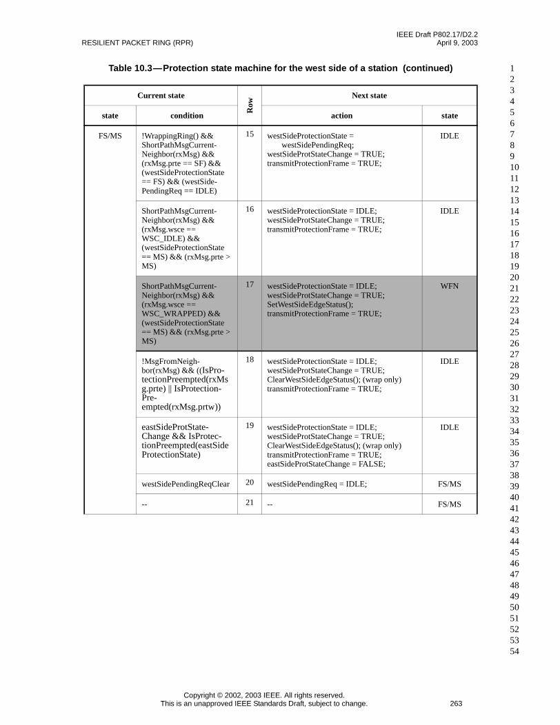
IEEE Draft P802.17/D2.2RESILIENT PACKET RING (RPR) April 9, 2003
Copyright © 2002, 2003 IEEE. All rights reserved.This is an unapproved IEEE Standards Draft, subject to change. 263
123456789101112131415161718192021222324252627282930313233343536373839404142434445464748495051525354
FS/MS !WrappingRing() &&ShortPathMsgCurrent-Neighbor(rxMsg) &&(rxMsg.prte == SF) &&(westSideProtectionState== FS) && (westSide-PendingReq == IDLE)
15 westSideProtectionState =westSidePendingReq;
westSideProtStateChange = TRUE;transmitProtectionFrame = TRUE;
IDLE
ShortPathMsgCurrent-Neighbor(rxMsg) &&(rxMsg.wsce ==WSC_IDLE) &&(westSideProtectionState== MS) && (rxMsg.prte >MS)
16 westSideProtectionState = IDLE;westSideProtStateChange = TRUE;transmitProtectionFrame = TRUE;
IDLE
ShortPathMsgCurrent-Neighbor(rxMsg) &&(rxMsg.wsce ==WSC_WRAPPED) &&(westSideProtectionState== MS) && (rxMsg.prte >MS)
17 westSideProtectionState = IDLE;westSideProtStateChange = TRUE;SetWestSideEdgeStatus();transmitProtectionFrame = TRUE;
WFN
!MsgFromNeigh-bor(rxMsg) && ((IsPro-tectionPreempted(rxMsg.prte) || IsProtection-Pre-empted(rxMsg.prtw))
18 westSideProtectionState = IDLE;westSideProtStateChange = TRUE;ClearWestSideEdgeStatus(); (wrap only)transmitProtectionFrame = TRUE;
IDLE
eastSideProtState-Change && IsProtec-tionPreempted(eastSideProtectionState)
19 westSideProtectionState = IDLE;westSideProtStateChange = TRUE;ClearWestSideEdgeStatus(); (wrap only)transmitProtectionFrame = TRUE;eastSideProtStateChange = FALSE;
IDLE
westSidePendingReqClear 20 westSidePendingReq = IDLE; FS/MS
-- 21 -- FS/MS
Table 10.3—Protection state machine for the west side of a station (continued)
Current state
Row
Next state
state condition action state

IEEE Draft P802.17/D2.2April 9, 2003 DRAFT STANDARD FOR
Copyright © 2002, 2003 IEEE. All rights reserved.264 This is an unapproved IEEE Standards Draft, subject to change.
123456789
101112131415161718192021222324252627282930313233343536373839404142434445464748495051525354
SF/SD localFailureClear &&westSidePendingReq ==IDLE
22 westSideProtectionState = WTR;westSideProtStateChange = TRUE;transmitProtectionFrame = TRUE;
WTR
localFailureClear &&(westSidePendingReq !=IDLE) && IsProtection-Granted(westSidePendin-gReq)
23 westSideProtectionState =westSidePendingReq;
westSideProtStateChange = TRUE;westSidePendingReq = IDLE;setWestSideEdgeStatus(); (wrap only)transmitProtectionFrame = TRUE;
SF/SD
IsProtectionGranted(local-Failure)
24 westSideProtectionState = localFailure;westSideProtStateChange = TRUE;setWestSideEdgeStatus(); (wrap only)transmitProtectionFrame = TRUE;
SF/SD
localFailureClear &&(westSidePendingReq !=IDLE) && !IsProtection-Granted(westSidePendin-gReq)
25 westSideProtectionState =westSidePendingReq;
westSideProtStateChange = TRUE;westSidePendingReq = IDLE;clearWestSideEdgeStatus(); (wrap only)transmitProtectionFrame = TRUE;
SF/SD
IsProtectionGranted(local-Request)
26 westSidePendingReq =westSideProtectionState;
westSideProtectionState = localRequest;westSideProtStateChange = TRUE;SetWestSideEdgeStatus(); (wrap only)transmitProtectionFrame = TRUE;.
FS/MS
WrappingRing() &&ShortPathMsgCurrent-Neighbor(rxMsg) &&(rxMsg.prte == PRT_FS)&& (westSideProtection-State != SF)
27 SetWestSideEdgeStatus();transmitProtectionFrame = TRUE;
SF/SD
WrappingRing() &&!MsgFromNeigh-bor(rxMsg) && ((IsPro-tectionPreempted(rxMsg.prte) || IsProtection-Pre-empted(rxMsg.prtw))
28 ClearWestSideEdgeStatus();transmitProtectionFrame = TRUE;
SF/SD
WrappingRing() && east-SideProtStateChange&& IsProtectionPre-empted(eastSideProtec-tionState)
29 ClearWestSideEdgeStatus();transmitProtectionFrame = TRUE;
SF/SD
-- 30 -- SF/SD
Table 10.3—Protection state machine for the west side of a station (continued)
Current state
Row
Next state
state condition action state

IEEE Draft P802.17/D2.2RESILIENT PACKET RING (RPR) April 9, 2003
Copyright © 2002, 2003 IEEE. All rights reserved.This is an unapproved IEEE Standards Draft, subject to change. 265
123456789101112131415161718192021222324252627282930313233343536373839404142434445464748495051525354
WFN WrappingRing() &&ShortPathMsgCurrent-Neighbor(rxMsg) &&(rxMsg.wsce ==WSC_IDLE)
31 ClearWestSideEdgeStatus();transmitProtectionFrame = TRUE;
IDLE
WrappingRing() &&IsProtectionGranted(local-Request)
32 westSideProtectionState = localRequest;westSideProtStateChange = TRUE;SetWestSideEdgeStatus();transmitProtectionFrame = TRUE;
FS/MS
WrappingRing() &&IsProtectionGranted(local-Failure)
33 westSideProtectionState = localFailure;westSideProtStateChange = TRUE;SetWestSideEdgeStatus();transmitProtectionFrame = TRUE;
SF/SD
WrappingRing() &&!IsProtection-Granted(localFailure)
34 westSideProtectionState = localFailure;westSideProtStateChange = TRUE;transmitProtectionFrame = TRUE;
SF/SD
-- 35 -- WFN
Table 10.3—Protection state machine for the west side of a station (continued)
Current state
Row
Next state
state condition action state

IEEE Draft P802.17/D2.2April 9, 2003 DRAFT STANDARD FOR
Copyright © 2002, 2003 IEEE. All rights reserved.266 This is an unapproved IEEE Standards Draft, subject to change.
123456789
101112131415161718192021222324252627282930313233343536373839404142434445464748495051525354
WTR WrappingRing() &&ShortPathMsgCurrent-Neighbor(rxMsg) &&(rxMsg.prte ==PRT_IDLE) &&(rxMsg.wsce ==WSC_WRAPPED) &&wtrExpired && reversion-Mode
36 westSideProtectionState = IDLE;westSideProtStateChange = TRUE;ClearWestSideEdgeStatus();transmitProtectionFrame = TRUE;
IDLE
WrappingRing() &&ShortPathMsgCurrent-Neighbor(rxMsg) &&(rxMsg.wsce ==WSC_WRAPPED) &&(rxMsg.prte > PRT_WTR)
37 westSideProtectionState = IDLE;westSideProtStateChange = TRUE;SetWestSideEdgeStatus();transmitProtectionFrame = TRUE;
WFN
WrappingRing() && wtr-Expired && reversion-Mode && (rxMsg.prte ==PRT_WTR)
38 westSideProtectionState = IDLE;westSideProtStateChange = TRUE;transmitProtectionFrame = TRUE;
WFN
!WrappingRing() && wtr-Expired && reversion-Mode
39 westSideProtectionState = IDLE;westSideProtStateChange = TRUE;transmitProtectionFrame = TRUE;
IDLE
ShortPathMsgNewNeigh-bor(rxMsg) &&(rxMsg.prte ==PRT_IDLE)
40 westSideProtectionState = IDLE;westSideProtStateChange = TRUE;ClearWestSideEdgeStatus(); (wrap only)transmitProtectionFrame = TRUE;westNeighborMACAddress = rxMsg.sa;
IDLE
IsProtectionGranted(local-Request)
41 westSideProtectionState = localRequest;westSideProtStateChange = TRUE;SetWestSideEdgeStatus(); (wrap only)transmitProtectionFrame = TRUE;
FS/MS
IsProtectionGranted(local-Failure)
42 westSideProtectionState = localFailure;westSideProtStateChange = TRUE;SetWestSideEdgeStatus(); (wrap only)transmitProtectionFrame = TRUE;
SF/SD
!MsgFromNeigh-bor(rxMsg) && ((IsPro-tectionPreempted(rxMsg.prte) || IsProtection-Pre-empted(rxMsg.prtw))
43 westSideProtectionState = IDLE;westSideProtStateChange = TRUE;ClearWestSideEdgeStatus(); (wrap only)transmitProtectionFrame = TRUE;
IDLE
WrappingRing() && east-SideProtStateChange&& IsProtectionPre-empted(eastSideProtec-tionState)
44 westSideProtectionState = IDLE;westSideProtStateChange = TRUE;ClearWestSideEdgeStatus();transmitProtectionFrame = TRUE;
IDLE
45 IDLE
Table 10.3—Protection state machine for the west side of a station (continued)
Current state
Row
Next state
state condition action state

IEEE Draft P802.17/D2.2RESILIENT PACKET RING (RPR) April 9, 2003
Copyright © 2002, 2003 IEEE. All rights reserved.This is an unapproved IEEE Standards Draft, subject to change. 267
123456789101112131415161718192021222324252627282930313233343536373839404142434445464748495051525354
Row 10.3-1: Local administrative request granted. Protection-related information updated for inclusion inthe topology database information associated with the station. Causes transmission of TP frames reportingthe new station protection information contained in the topology database, and wrap for wrapping rings.
Row 10.3-2: Local failure causes wrap. Wrap check is not necessary for steering rings. Protection-relatedinformation updated for inclusion in the topology database information associated with the station. Causestransmission of TP frames reporting the new station protection information contained in the topologydatabase, and wrap for wrapping rings.
Row 10.3-3: Local failure does not cause wrap. Wrap check is not necessary for steering rings.Protection-related information updated for inclusion in the topology database information associated withthe station. Causes transmission of TP frames reporting the new station protection information contained inthe topology database.
Row 10.3-4: Optional, wrap only. Protection request received from neighbor on the short path stating thatthe neighbor is wrapped. This causes this station to wrap and to transition to WFN state. The WFN statecorresponds to when a station is wrapped but reporting an IDLE protection state on the receive link that it ismonitoring.
Row 10.3-5: Remain in IDLE state.
Row 10.3-6: FS/MS cleared but wrap protection not granted for non-IDLE pending request (either failure oradministrative request). Wrap check is not necessary for steering rings. This can occur if the pendingcondition is SD but there is already a SD elsewhere on the ring. This results in reporting of the newprotection condition, and in clearing of any existing wrap on the interface. Protection-related informationupdated for inclusion in the topology database information associated with the station.
Row 10.3-7: FS/MS cleared and wrap protection granted for non-IDLE pending request (either failure oradministrative request). Wrap check is not necessary for steering rings. Protection-related informationupdated for inclusion in the topology database information associated with the station. Causes transmissionof TP frames reporting the new station protection information contained in the topology database, and inwrapping on the interface.
Row 10.3-8: FS/MS cleared and no pending request. This results in reporting of IDLE for this link, and inclearing of any existing wrap on the interface. Protection-related information updated for inclusion in thetopology database information associated with the station.
Row 10.3-9: Local administrative request granted. Protection-related information updated for inclusion inthe topology database information associated with the station. Causes transmission of TP frames reportingthe new station protection information contained in the topology database, and wrap for wrapping rings.
Row 10.3-10: Local failure causes wrap (check is not necessary for steering rings). Protection-relatedinformation updated for inclusion in the topology database information associated with the station. Causestransmission of TP frames reporting the new station protection information contained in the topologydatabase, and wrap for wrapping rings.
Row 10.3-11: Local failure does not cause wrap and existing link protection state is FS. Wrap check is notnecessary for steering rings. Causes failure condition to go pending.
Row 10.3-12: Local failure does not cause wrap and existing link protection state is MS. Wrap check is notnecessary for steering rings. Causes MS to be cleared and transmission of TP frames reporting the new linkprotection state. Protection-related information updated for inclusion in the topology database informationassociated with the station.
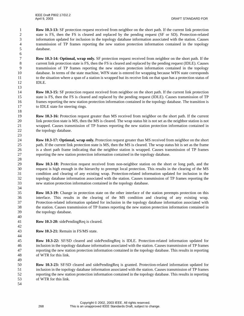
IEEE Draft P802.17/D2.2April 9, 2003 DRAFT STANDARD FOR
Copyright © 2002, 2003 IEEE. All rights reserved.268 This is an unapproved IEEE Standards Draft, subject to change.
123456789
101112131415161718192021222324252627282930313233343536373839404142434445464748495051525354
Row 10.3-13: SF protection request received from neighbor on the short path. If the current link protectionstate is FS, then the FS is cleared and replaced by the pending request (SF or SD). Protection-relatedinformation updated for inclusion in the topology database information associated with the station. Causestransmission of TP frames reporting the new station protection information contained in the topologydatabase.
Row 10.3-14: Optional, wrap only. SF protection request received from neighbor on the short path. If thecurrent link protection state is FS, then the FS is cleared and replaced by the pending request (IDLE). Causestransmission of TP frames reporting the new station protection information contained in the topologydatabase. In terms of the state machine, WFN state is entered for wrapping because WFN state correspondsto the situation where a span of a station is wrapped but its receive link on that span has a protection status ofIDLE.
Row 10.3-15: SF protection request received from neighbor on the short path. If the current link protectionstate is FS, then the FS is cleared and replaced by the pending request (IDLE). Causes transmission of TPframes reporting the new station protection information contained in the topology database. The transition isto IDLE state for steering rings.
Row 10.3-16: Protection request greater than MS received from neighbor on the short path. If the currentlink protection state is MS, then the MS is cleared. The wrap status bit is not set as the neighbor station is notwrapped. Causes transmission of TP frames reporting the new station protection information contained inthe topology database.
Row 10.3-17: Optional, wrap only. Protection request greater than MS received from neighbor on the shortpath. If the current link protection state is MS, then the MS is cleared. The wrap status bit is set as the frameis a short path frame indicating that the neighbor station is wrapped. Causes transmission of TP framesreporting the new station protection information contained in the topology database.
Row 10.3-18: Protection request received from non-neighbor station on the short or long path, and therequest is high enough in the hierarchy to preempt local protection. This results in the clearing of the MScondition and clearing of any existing wrap. Protection-related information updated for inclusion in thetopology database information associated with the station. Causes transmission of TP frames reporting thenew station protection information contained in the topology database.
Row 10.3-19: Change in protection state on the other interface of the station preempts protection on thisinterface. This results in the clearing of the MS condition and clearing of any existing wrap.Protection-related information updated for inclusion in the topology database information associated withthe station. Causes transmission of TP frames reporting the new station protection information contained inthe topology database.
Row 10.3-20: sidePendingReq is cleared.
Row 10.3-21: Remain in FS/MS state.
Row 10.3-22: SF/SD cleared and sidePendingReq is IDLE. Protection-related information updated forinclusion in the topology database information associated with the station. Causes transmission of TP framesreporting the new station protection information contained in the topology database. This results in reportingof WTR for this link.
Row 10.3-23: SF/SD cleared and sidePendingReq is granted. Protection-related information updated forinclusion in the topology database information associated with the station. Causes transmission of TP framesreporting the new station protection information contained in the topology database. This results in reportingof WTR for this link.

IEEE Draft P802.17/D2.2RESILIENT PACKET RING (RPR) April 9, 2003
Copyright © 2002, 2003 IEEE. All rights reserved.This is an unapproved IEEE Standards Draft, subject to change. 269
123456789101112131415161718192021222324252627282930313233343536373839404142434445464748495051525354
Row 10.3-24: Local failure causes update of reported information to the rest of the ring (SD to SF).Protection-related information updated for inclusion in the topology database information associated withthe station. Causes transmission of TP frames reporting the new station protection information contained inthe topology database, and wrap for wrapping rings.
Row 10.3-25: SF/SD cleared and sidePendingReq is not granted. Protection-related information updated forinclusion in the topology database information associated with the station. Causes transmission of TP framesreporting the new station protection information contained in the topology database. This results in reportingof WTR for this link.
Row 10.3-26: Local administrative request granted. Causes existing local failure condition to go pending.Protection-related information updated for inclusion in the topology database information associated withthe station. Causes transmission of TP frames reporting the new station protection information contained inthe topology database, and wrap.
Row 10.3-27: Optional, wrap only. FS protection request received from neighbor on the short path statingthat the neighbor is wrapped, and local link protection state is not SF. Protection-related information updatedfor inclusion in the topology database information associated with the station. Causes transmission of TPframes reporting the new station protection information contained in the topology database., and wrap.
Row 10.3-28: Optional, wrap only. Protection request received from non-neighbor station on the short orlong path stating that the non-neighbor station is wrapped or not wrapped, and the request is high enough inthe hierarchy to preempt local protection. This results in the clearing of any existing wrap. Protection-relatedinformation updated for inclusion in the topology database information associated with the station. Causestransmission of TP frames reporting the new station protection information contained in the topologydatabase.
Row 10.3-29: Optional, wrap only. Protection request received from the other interface of the station thatpreempts protection on this interface. This results in the clearing of any existing wrap. Protection-relatedinformation updated for inclusion in the topology database information associated with the station. Causestransmission of TP frames reporting the new station protection information contained in the topologydatabase.
Row 10.3-30: Remain in SF/SD state.
Row 10.3-31: Optional, wrap only. TP message received from neighbor on the short or long path statingthat the neighbor is no longer wrapped. Protection-related information updated for inclusion in the topologydatabase information associated with the station. Causes transmission of TP frames reporting the new stationprotection information contained in the topology database, and clearing of the existing wrap.
Row 10.3-32: Optional, wrap only. Local administrative request granted. Protection-related informationupdated for inclusion in the topology database information associated with the station. Causes transmissionof TP frames reporting the new station protection information contained in the topology database, and wrap.
Row 10.3-33: Optional, wrap only. Local failure causes wrap. Protection-related information updated forinclusion in the topology database information associated with the station. Causes transmission of TP framesreporting the new station protection information contained in the topology database, and wrap.
Row 10.3-34: Optional, wrap only. Local failure does not cause wrap. Protection-related informationupdated for inclusion in the topology database information associated with the station. Causes transmissionof TP frames reporting the new station protection information contained in the topology database.
Row 10.3-35: Optional, wrap only. Remain in WFN state.
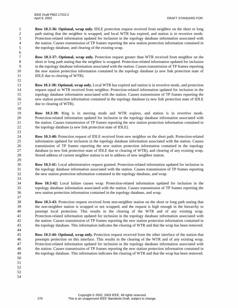
IEEE Draft P802.17/D2.2April 9, 2003 DRAFT STANDARD FOR
Copyright © 2002, 2003 IEEE. All rights reserved.270 This is an unapproved IEEE Standards Draft, subject to change.
123456789
101112131415161718192021222324252627282930313233343536373839404142434445464748495051525354
Row 10.3-36: Optional, wrap only. IDLE protection request received from neighbor on the short or longpath stating that the neighbor is wrapped, and local WTR has expired, and station is in revertive mode.Protection-related information updated for inclusion in the topology database information associated withthe station. Causes transmission of TP frames reporting the new station protection information contained inthe topology database, and clearing of the existing wrap.
Row 10.3-37: Optional, wrap only. Protection request greater than WTR received from neighbor on theshort or long path stating that the neighbor is wrapped. Protection-related information updated for inclusionin the topology database information associated with the station. Causes transmission of TP frames reportingthe new station protection information contained in the topology database (a new link protection state ofIDLE due to clearing of WTR).
Row 10.3-38: Optional, wrap only. Local WTR has expired and station is in revertive mode, and protectionrequest equal to WTR received from neighbor. Protection-related information updated for inclusion in thetopology database information associated with the station. Causes transmission of TP frames reporting thenew station protection information contained in the topology database (a new link protection state of IDLEdue to clearing of WTR).
Row 10.3-39: Ring is in steering mode and WTR expires, and station is in revertive mode.Protection-related information updated for inclusion in the topology database information associated withthe station. Causes transmission of TP frames reporting the new station protection information contained inthe topology database (a new link protection state of IDLE).
Row 10.3-40: Protection request of IDLE received from new neighbor on the short path. Protection-relatedinformation updated for inclusion in the topology database information associated with the station. Causestransmission of TP frames reporting the new station protection information contained in the topologydatabase (a new link protection state of IDLE due to clearing of WTR), and clearing of any existing wrap.Stored address of current neighbor station is set to address of new neighbor station.
Row 10.3-41: Local administrative request granted. Protection-related information updated for inclusion inthe topology database information associated with the station. Causes transmission of TP frames reportingthe new station protection information contained in the topology database, and wrap.
Row 10.3-42: Local failure causes wrap. Protection-related information updated for inclusion in thetopology database information associated with the station. Causes transmission of TP frames reporting thenew station protection information contained in the topology database, and wrap.
Row 10.3-43: Protection request received from non-neighbor station on the short or long path stating thatthe non-neighbor station is wrapped or not wrapped, and the request is high enough in the hierarchy topreempt local protection. This results in the clearing of the WTR and of any existing wrap.Protection-related information updated for inclusion in the topology database information associated withthe station. Causes transmission of TP frames reporting the new station protection information contained inthe topology database. This information indicates the clearing of WTR and that the wrap has been removed.
Row 10.3-44: Optional, wrap only. Protection request received from the other interface of the station thatpreempts protection on this interface. This results in the clearing of the WTR and of any existing wrap.Protection-related information updated for inclusion in the topology database information associated withthe station. Causes transmission of TP frames reporting the new station protection information contained inthe topology database. This information indicates the clearing of WTR and that the wrap has been removed.

IEEE Draft P802.17/D2.2RESILIENT PACKET RING (RPR) April 9, 2003
Copyright © 2002, 2003 IEEE. All rights reserved.This is an unapproved IEEE Standards Draft, subject to change. 271
123456789101112131415161718192021222324252627282930313233343536373839404142434445464748495051525354
10.7 Topology database
Under certain conditions such as a failed span in a bidirectional ring, a station is only able to receive TP andTLV frames from the other stations on the ring on one ringlet. It is a requirement to be able to construct acomplete topology database reflecting connectivity information on both ringlets. Hence, a single topologydatabase showing information for both ringlets can meet this requirement as well as facilitate maintenanceof a consistent database. The hop count to another station can be calculated through examination of thetopology image. For each ringlet, the topology image must be completed up to the station whose hop countis desired.
There are multiple representations of the topology database given in this subclause. The first is a logicalview of the database that conforms to the MIB-level view. The second is a lower level view of the databasethat can be modified easily for various topology perturbations.
10.7.1 Logical representation of topology database
There is one entry (row) for each station known to be on the ring. The values of each entry (not including theTLV entries covered in 10.10.1) are:
a) the MAC address of the station described by the entry, stationMACAddress,b) the downstream hop count on ringlet0, ringlet0Hops,c) the downstream hop count on ringlet1, ringlet1Hops,d) station preferences, stationWrapPref and stationJumboPref,e) the link protection state of the receive link from the west station, westSideProtectionState,f) the link protection state of the receive link from the east station, eastSideProtectionState,g) the edge or wrap status of the station’s west span, westSideEdgeStatus,h) the edge or wrap status of the station’s east span, eastSideEdgeStatus,i) the data reachability downstream on ringlet0, ringlet0Reachability, andj) the data reachability downstream on ringlet1, ringlet1Reachability.
The receive link protection state can be any of the TP frame request values given in Table 10.1. The reservedsubclassA0 bandwidth is described in 10.10.4.2.
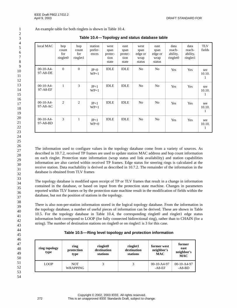
IEEE Draft P802.17/D2.2April 9, 2003 DRAFT STANDARD FOR
Copyright © 2002, 2003 IEEE. All rights reserved.272 This is an unapproved IEEE Standards Draft, subject to change.
123456789
101112131415161718192021222324252627282930313233343536373839404142434445464748495051525354
An example table for both ringlets is shown in Table 10.4.
The information used to configure values in the topology database come from a variety of sources. Asdescribed in 10.7.2, received TP frames are used to update station MAC address and hop count informationon each ringlet. Protection state information (wrap status and link availability) and station capabilitiesinformation are also carried within received TP frames. Edge status for steering rings is calculated at thereceive station. Data reachability is derived as described in 10.7.2. The remainder of the information in thedatabase is obtained from TLV frames
The topology database is modified upon receipt of TP or TLV frames that result in a change in informationcontained in the database, or based on input from the protection state machine. Changes in parametersreported within TLV frames or by the protection state machine result in the modification of fields within thedatabase, but not the position of stations in the topology.
There is also non-per-station information stored in the logical topology database. From the information inthe topology database, a number of useful pieces of information can be derived. These are shown in Table10.5. For the topology database in Table 10.4, the corresponding ringlet0 and ringlet1 edge statusinformation both correspond to LOOP (for fully connected bidirectional ring), rather than to CHAIN (for astring). The number of destination stations on ringlet0 or on ringlet1 is 3 for this case.
Table 10.5—Ring level topology and protection information
Table 10.4—Topology and status database table
local MAC hopcount
forringlet0
hopcount
forringlet1
stationprefer-ences
westspan
protec-tionstate
eastspan
protec-tionstate
westspan
edge orwrapstatus
eastspan
edge orwrapstatus
datareach-ability,ringlet0
datareach-ability,ringlet1
TLVfields
00-10-A4-97-A8-DE
0 0 JP=0WP=1
IDLE IDLE No No Yes Yes see10.10.
1
00-10-A4-97-A8-EF
1 3 JP=1WP=1
IDLE IDLE No No Yes Yes see10.10.
1
00-10-A4-97-A8-AC
2 2 JP=1WP=1
IDLE IDLE No No Yes Yes see10.10.
1
00-10-A4-97-A8-BD
3 1 JP=1WP=0
IDLE IDLE No No Yes Yes see10.10.
1
ring topologytype
ringprotection
type
ringlet0destination
stations
ringlet1destination
stations
former westneighbor's
MAC
formereast
neighbor'sMAC
LOOP NOTWRAPPING
3 3 00-10-A4-97-A8-EF
00-10-A4-97-A8-BD

IEEE Draft P802.17/D2.2RESILIENT PACKET RING (RPR) April 9, 2003
Copyright © 2002, 2003 IEEE. All rights reserved.This is an unapproved IEEE Standards Draft, subject to change. 273
123456789101112131415161718192021222324252627282930313233343536373839404142434445464748495051525354
The ring level fields are:
a) ring topology type, ringTopologyType,b) ring protection type, ringProtectionType,c) number of destination stations on ringlet0, ringlet0Hops,d) number of destination stations on ringlet1, ringlet1Hops,e) former west neighbor station’s MAC address, westFormerNeighborMACAddress, andf) former east neighbor station’s MAC address, eastFormerNeighborMACAddress.
The method of calculating the variables westSideEdgeStatus, eastSideEdgeStatus, ringlet0Reachability,ringlet1Reachability, ringTopologyType, ringlet0Hops, and ringlet1Hops are described in 10.7.2.
A station determines itself to be isolated if the receive links on both the east and west interfaces of a stationhave a protection state of signal fail (SF). An isolated station shall remove all entries from its local topologyimage, but shall transfer its own east neighbor and west neighbor information to the former east neighborand former west neighbor fields in the database before clearing the east neighbor and west neighbor fields.The information in the former east neighbor and former west neighbor fields is needed to determine whethera link should be brought up immediately, as described in 10.6.1.
The topology database also contains the MAC address information of the neighbor previously connected toeach interface of the local station. This information is only relevant to the local station, and can be storedseparately from the information shown in Table 10.4. This information is stored in the topology databasebecause it is required by the protection protocol. The topology module notifies the protection module whenthis information has changed. The former neighbor entries are rewritten upon a change in the value of thecurrent neighbor entry for each respective interface.
Upon detection of signal fail on a given interface (west for example), the west neighbor MAC address isinvalidated as described in 10.7.2 (cleared from the logical topology database point of view). Upon detectionof a new neighbor on that interface, the MAC address of the new neighbor is first compared to the formerwest neighbor MAC address. The protection module is notified if the new neighbor and former neighborMAC addresses are different. The new neighbor MAC address is then copied into both the west neighborMAC address and the former west neighbor MAC address.
10.7.2 Lower level representation of topology database
The MAC has topology database components illustrated in Figure 10.11. The signed index associated withthis database represents the ringlet0 distance-to-source hops. The positive-index and negative-index entriesare derived from protection frames received on ringlet1 and ringlet0 respectively; the magnitude of the indexequals 256 minus the protection frame’s ttl value.

IEEE Draft P802.17/D2.2April 9, 2003 DRAFT STANDARD FOR
Copyright © 2002, 2003 IEEE. All rights reserved.274 This is an unapproved IEEE Standards Draft, subject to change.
123456789
101112131415161718192021222324252627282930313233343536373839404142434445464748495051525354
The ringlet0Hops and ringlet1Hops fields specify numbers of ringlet0 and ringlet1 destination stationsrespectively. The Loop bit is 0 and 1 for chain and loop topologies respectively.
Within each array, the valid bit values of 0 and 1 correspond to unvalidated and validated entry statusrespectively. The valid bit is cleared for all stations downstream of a detected edge; the valid bit is set whena protection frame is received from a station beyond a detected edge in a chain topology. The 48-bitmacAddress field and the info field are copies of fields within protection frames.
Since the database components are sometimes accessed at line-rate speeds, each datapath is expected to havea distinct copy of the topology database. This avoids mandating a high-speed communication path betweendatapaths, at a modest cost of supporting low-rate datapath-to-datapath discovery-frame communications.
To calculate westSideEdgeStatus and eastSideEdgeStatus:
In a steering ring, an edge is detected based on the following rules:
An edge is present on a span if:
a) FS or SF present on one or both links of any span, orb) SD present on one or both links of span, and there is no other span with SD condition, orc) MS present on one or both links of span, and there is no other span with MS condition, ord) WTR present on one or both links of span, and there is no other span with WTR condition.
In a wrapping ring, an edge is present wherever there is a wrap. The above check for steering rings matchesthe conditions that will result in at least one wrap being present on the ring. The implication of having anedge present on a given span is described under station validity.
A half-severed link transmits information in one direction but not the other (only one of the two links isoperational). Half-severed links, just like fully severed links are edges in that data does not flow across anedge link from a frame transfer perspective.
Figure 10.11—Topology database parameters
–
–
–1
254255
……
1 48 bits
valid
–0macAddressmacAddress
macAddress
macAddressringlet1Hops
8
info
infoinfo
info
–
––
…
macAddress
macAddressmacAddress info
info
info
–1
…
–255
se Loop1
… …
… …
ringlet0Hops
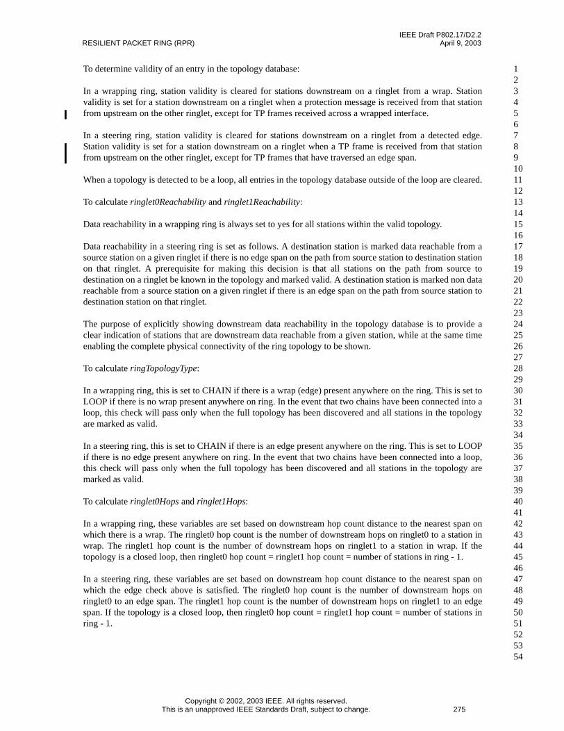
IEEE Draft P802.17/D2.2RESILIENT PACKET RING (RPR) April 9, 2003
Copyright © 2002, 2003 IEEE. All rights reserved.This is an unapproved IEEE Standards Draft, subject to change. 275
123456789101112131415161718192021222324252627282930313233343536373839404142434445464748495051525354
To determine validity of an entry in the topology database:
In a wrapping ring, station validity is cleared for stations downstream on a ringlet from a wrap. Stationvalidity is set for a station downstream on a ringlet when a protection message is received from that stationfrom upstream on the other ringlet, except for TP frames received across a wrapped interface.
In a steering ring, station validity is cleared for stations downstream on a ringlet from a detected edge.Station validity is set for a station downstream on a ringlet when a TP frame is received from that stationfrom upstream on the other ringlet, except for TP frames that have traversed an edge span.
When a topology is detected to be a loop, all entries in the topology database outside of the loop are cleared.
To calculate ringlet0Reachability and ringlet1Reachability:
Data reachability in a wrapping ring is always set to yes for all stations within the valid topology.
Data reachability in a steering ring is set as follows. A destination station is marked data reachable from asource station on a given ringlet if there is no edge span on the path from source station to destination stationon that ringlet. A prerequisite for making this decision is that all stations on the path from source todestination on a ringlet be known in the topology and marked valid. A destination station is marked non datareachable from a source station on a given ringlet if there is an edge span on the path from source station todestination station on that ringlet.
The purpose of explicitly showing downstream data reachability in the topology database is to provide aclear indication of stations that are downstream data reachable from a given station, while at the same timeenabling the complete physical connectivity of the ring topology to be shown.
To calculate ringTopologyType:
In a wrapping ring, this is set to CHAIN if there is a wrap (edge) present anywhere on the ring. This is set toLOOP if there is no wrap present anywhere on ring. In the event that two chains have been connected into aloop, this check will pass only when the full topology has been discovered and all stations in the topologyare marked as valid.
In a steering ring, this is set to CHAIN if there is an edge present anywhere on the ring. This is set to LOOPif there is no edge present anywhere on ring. In the event that two chains have been connected into a loop,this check will pass only when the full topology has been discovered and all stations in the topology aremarked as valid.
To calculate ringlet0Hops and ringlet1Hops:
In a wrapping ring, these variables are set based on downstream hop count distance to the nearest span onwhich there is a wrap. The ringlet0 hop count is the number of downstream hops on ringlet0 to a station inwrap. The ringlet1 hop count is the number of downstream hops on ringlet1 to a station in wrap. If thetopology is a closed loop, then ringlet0 hop count = ringlet1 hop count = number of stations in ring - 1.
In a steering ring, these variables are set based on downstream hop count distance to the nearest span onwhich the edge check above is satisfied. The ringlet0 hop count is the number of downstream hops onringlet0 to an edge span. The ringlet1 hop count is the number of downstream hops on ringlet1 to an edgespan. If the topology is a closed loop, then ringlet0 hop count = ringlet1 hop count = number of stations inring - 1.

IEEE Draft P802.17/D2.2April 9, 2003 DRAFT STANDARD FOR
Copyright © 2002, 2003 IEEE. All rights reserved.276 This is an unapproved IEEE Standards Draft, subject to change.
123456789
101112131415161718192021222324252627282930313233343536373839404142434445464748495051525354
10.7.2.1 Stable database structures
Stable database structures could reflect loop or chain topologies, as illustrated in the left and right sides ofFigure 10.12 respectively. In a loop topology, the local station’s entries are repeated on the two ends of theloop. This facilitates verification that the topology is a loop. In a chain topology, each side of the chain ter-minates where an edge is detected.
.
Editors’ Notes: To be removed prior to final publication.
Whether these rules need to be modified in passthrough scenarios must be evaluated.
Editors’ Notes: To be removed prior to final publication.
Additional work needs to be done by the PAH on this subclause, including the addition of a flow chart/statemachine. The PAH will target submission of modified text prior to the next meeting.
Editors’ Notes: To be removed prior to final publication.
The tables masquerading as Figures 10.12 and 10.13 must be converted into figures.
1) Stable loop topology
S1 S2 S3 S4 S5 S6
2) Stable chain topology
S1 S2 S3 S4 S5 S6
macAddressS51macAddressS61macAddressS11
macAddressS41macAddressS31
macAddressS21
infoinfoinfo
infoinfo
info
S2
……
macAddressS51macAddressS61macAddressS11
macAddressS41macAddressS31
infoinfoinfo
infoinfo
ringlet0Hops
Loop=1
0+1
-1
……
ringlet1Hops
… …
… …macAddressS21 info
macAddressS21 info
macAddressS11macAddressS21
infoinfo
S2
……
macAddressS51macAddressS61
macAddressS41macAddressS31
infoinfo
infoinfo
ringlet0Hops
Loop=0
0+1
-1
……
ringlet1Hops
……
… …
Figure 10.12—Stable database structures

IEEE Draft P802.17/D2.2RESILIENT PACKET RING (RPR) April 9, 2003
Copyright © 2002, 2003 IEEE. All rights reserved.This is an unapproved IEEE Standards Draft, subject to change. 277
123456789101112131415161718192021222324252627282930313233343536373839404142434445464748495051525354
10.7.2.2 Topology change sequences
A sequence of topology changes is illustrated in Figure 10.13. A stable closed-loop topology (1) has validpositive and negative entry index values and redundant entries. A single severed link (2) restricts thedatabase knowledge to an open-loop array, based on a pair of reports from the two edge stations. Twosevered links (3) further restricts the database knowledge to a smaller open-loop array, based on a pair ofreports from the two edge stations. Joining additional stations (4) requires more extensive database updates,with span extensions triggered by the remote edge-station reports.
Figure 10.13—Topology change sequences
1) Stable loop topology
S1 S2 S3 S4 S5 S6
2) Severed link opens the loop
S1 S2 S3 S4 S5 S6
macAddressS51macAddressS61macAddressS11
macAddressS41macAddressS31
macAddressS21
infoinfoinfo
infoinfo
info
S2
……
macAddressS51macAddressS61macAddressS11
macAddressS41macAddressS31
infoinfoinfo
infoinfo
ringlet0Hops
Loop=1
0+1
-1
……
ringlet1Hops
… …
… …macAddressS21 info
macAddressS21 info
macAddressS11macAddressS21
infoinfo
S2
……
macAddressS51macAddressS61
macAddressS41macAddressS31
infoinfo
infoinfo
ringlet0Hops
Loop=0
0+1
-1…
…ringlet1Hops
……
… …
3) Severed link depopulates the chain
S1 S2 S3 S4 S5 S6
4) Remote edge reports
S1 S2 S3 S7 S8 S9
macAddressS11macAddressS21
infoinfo
S2
……
macAddressS31 info ringlet0Hops
Loop=0
0+1
-1
……
ringlet1Hops
……
… …
macAddressS11macAddressS21
infoinfo
S2
……
macAddressS81macAddressS40macAddressS31
infoinfoinfo
ringlet0Hops
Loop=0
0+1
-1
……
ringlet1Hops
……
… …

IEEE Draft P802.17/D2.2April 9, 2003 DRAFT STANDARD FOR
Copyright © 2002, 2003 IEEE. All rights reserved.278 This is an unapproved IEEE Standards Draft, subject to change.
123456789
101112131415161718192021222324252627282930313233343536373839404142434445464748495051525354
l
The remote edge report is followed by TP frames (3) from closer stations, filling in the invalid databaseentries. The appearance of a connecting station (6) eliminates the possibility of edge-point reports, forcingthe report of a self-generated TP frame to confirm the closed-loop topology.
Alternatively, the addition of a connecting station may happen to (6a) extend the segment before convertingbetween chain and loop topologies. This has the advantage that the database entries are implied by the con-sistent incremental nature of the restoration.
5) Preceding edge reports
S1 S2 S3 S7 S8 S9
6) Restored loop topology
S1 S2 S3 S7 S8 S9
macAddressS11macAddressS21
infoinfo
S2
……
macAddressS81macAddressS71macAddressS31
infoinfoinfo
ringlet0Hops
Loop=0
0+1
-1
……
ringlet1Hops
……
… …
macAddressS81macAddressS91macAddressS11
macAddressS71macAddressS31
macAddressS21
infoinfoinfo
infoinfo
info
S2
……
macAddressS71macAddressS81macAddressS90
macAddressS41macAddressS31
infoinfoinfo
infoinfo
ringlet0Hops
Loop=1
0+1
-1
……
ringlet1Hops
… …
… …macAddressS21 info
macAddressS21 info
6a) Extended chain topology
S1 S2 S3 S7 S8 S9
6b) Restored loop topology
S1 S2 S3 S7 S8 S9
macAddressS11macAddressS21
infoinfo
S2
……
macAddressS81macAddressS91
macAddressS71macAddressS31
infoinfo
infoinfo
ringlet0Hops
Loop=0
0+1
-1
……
ringlet1Hops
… …
… …
macAddressS71macAddressS81macAddressS11
macAddressS61macAddressS31
macAddressS21
infoinfoinfo
infoinfo
info
S2
……
macAddressS71macAddressS81macAddressS11
macAddressS61macAddressS31
infoinfoinfo
infoinfo
ringlet0Hops
Loop=1
0+1
-1
……
ringlet1Hops
… …
… …macAddressS21 info
macAddressS21 info

IEEE Draft P802.17/D2.2RESILIENT PACKET RING (RPR) April 9, 2003
Copyright © 2002, 2003 IEEE. All rights reserved.This is an unapproved IEEE Standards Draft, subject to change. 279
123456789101112131415161718192021222324252627282930313233343536373839404142434445464748495051525354
10.7.3 Topology database update state machine
This subclause specifies the state machine for updating the topology database based on the followingtriggers:
a) Receipt of TP frames from the ring.b) Change of local protection state information.
10.7.3.1 Inputs
rcvdTPFrameThe received TP frame, consisting of the following relevant fields:prtw: Protection request type, west
FS, SF, SD, MS, WTR, IDLEprte: Protection request type, east
FS, SF, SD, MS, WTR, IDLEwscw: Wrapping status code, west
YES (1), NO (0)wsce: Wrapping status code, east
YES (1), NO (0)wp: Wrap preference
YES (1), NO (0)jp: Jumbo preference
YES (1), NO (0)ttl: Time to live
0 to 255ri: Ringlet indicator
0, 1sa: Source MAC address
rcvdRingletIDThe ringlet ID of the ringlet on which rcvdTPFrame is received.
localProtInfoThe protection information of the local station, consisting of the following:westSpanProtState: Protection state of west span
FS, SF, SD, MS, WTR, IDLEeastSpanProtState: Protection state of east span
FS, SF, SD, MS, WTR, IDLEwestWrapStatus: Wrap status of west span (provided by protection state machine for wrapping ringonly)
YES, NOeastWrapStatus: Wrap status of east span (provided by protection state machine for wrapping ringonly)
YES, NOwestNeighborMACAddress: MAC address of neighbor station on west spaneastNeighborMACAddress: MAC address of neighbor station on east span
topologyStableInput from topology validation state machine.TRUE, FALSE

IEEE Draft P802.17/D2.2April 9, 2003 DRAFT STANDARD FOR
Copyright © 2002, 2003 IEEE. All rights reserved.280 This is an unapproved IEEE Standards Draft, subject to change.
123456789
101112131415161718192021222324252627282930313233343536373839404142434445464748495051525354
10.7.3.2 Constants
FSForced switch.
SFSignal fail.
SDSignal degrade.
MSManual switch.
WTRWait to restore.
IDLEIdle.
10.7.3.3 Variables
topoDBCollection of information contained in the topology database.
localProtInfoChangeIndication that the protection information of the local station has changed.
miscablingDefectRinglet0Indication that a miscabling defect is present on ringlet0.
miscablingDefectRinglet1Indication that a miscabling defect is present on ringlet1.
10.7.3.4 Functions
The functions below are used in the topology database update state diagram.
CheckForMiscablingThe purpose of this function is to check for a miscabling defect based on a received TP frame.
CheckForMiscabling(Frame)(Frame.ri != rcvdRingletID)
Values:TRUE: Miscabling defect present.FALSE: Miscabling defect not present.
IndexTPThe purpose of this function is to determine the topology database index value corresponding tothe received TP frame.
IndexTP(Frame)if (rcvdRingletID == 1)
return (MAX_STATIONS - Frame.ttl + 1);else
return (-1)*(MAX_STATIONS - Frame.ttl + 1);
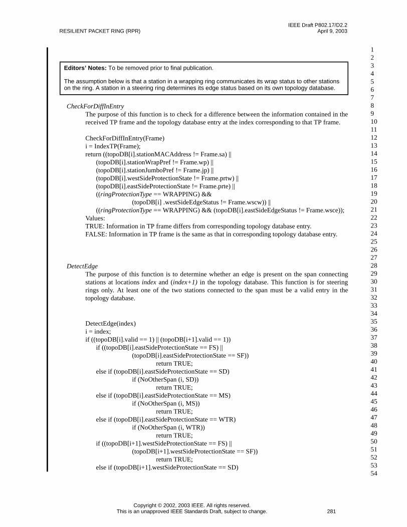
IEEE Draft P802.17/D2.2RESILIENT PACKET RING (RPR) April 9, 2003
Copyright © 2002, 2003 IEEE. All rights reserved.This is an unapproved IEEE Standards Draft, subject to change. 281
123456789101112131415161718192021222324252627282930313233343536373839404142434445464748495051525354
CheckForDiffInEntryThe purpose of this function is to check for a difference between the information contained in thereceived TP frame and the topology database entry at the index corresponding to that TP frame.
CheckForDiffInEntry(Frame)i = IndexTP(Frame);return ((topoDB[i].stationMACAddress != Frame.sa) ||
(topoDB[i].stationWrapPref != Frame.wp) ||(topoDB[i].stationJumboPref != Frame.jp) ||(topoDB[i].westSideProtectionState != Frame.prtw) ||(topoDB[i].eastSideProtectionState != Frame.prte) ||((ringProtectionType == WRAPPING) &&
(topoDB[i] .westSideEdgeStatus != Frame.wscw)) ||((ringProtectionType == WRAPPING) && (topoDB[i].eastSideEdgeStatus != Frame.wsce));
Values:TRUE: Information in TP frame differs from corresponding topology database entry.FALSE: Information in TP frame is the same as that in corresponding topology database entry.
DetectEdgeThe purpose of this function is to determine whether an edge is present on the span connectingstations at locations index and (index+1) in the topology database. This function is for steeringrings only. At least one of the two stations connected to the span must be a valid entry in thetopology database.
DetectEdge(index)i = index;if ((topoDB[i].valid == 1) || (topoDB[i+1].valid == 1))
if ((topoDB[i].eastSideProtectionState == FS) ||(topoDB[i].eastSideProtectionState == SF))
return TRUE;else if (topoDB[i].eastSideProtectionState == SD)
if (NoOtherSpan (i, SD))return TRUE;
else if (topoDB[i].eastSideProtectionState == MS)if (NoOtherSpan (i, MS))
return TRUE;else if (topoDB[i].eastSideProtectionState == WTR)
if (NoOtherSpan (i, WTR))return TRUE;
if ((topoDB[i+1].westSideProtectionState == FS) ||(topoDB[i+1].westSideProtectionState == SF))
return TRUE;else if (topoDB[i+1].westSideProtectionState == SD)
Editors’ Notes: To be removed prior to final publication.
The assumption below is that a station in a wrapping ring communicates its wrap status to other stationson the ring. A station in a steering ring determines its edge status based on its own topology database.
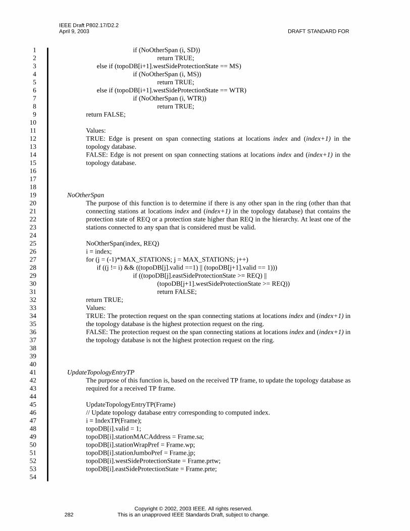
IEEE Draft P802.17/D2.2April 9, 2003 DRAFT STANDARD FOR
Copyright © 2002, 2003 IEEE. All rights reserved.282 This is an unapproved IEEE Standards Draft, subject to change.
123456789
101112131415161718192021222324252627282930313233343536373839404142434445464748495051525354
if (NoOtherSpan (i, SD))return TRUE;
else if (topoDB[i+1].westSideProtectionState == MS)if (NoOtherSpan (i, MS))
return TRUE;else if (topoDB[i+1].westSideProtectionState == WTR)
if (NoOtherSpan (i, WTR))return TRUE;
return FALSE;
Values:TRUE: Edge is present on span connecting stations at locations index and (index+1) in thetopology database.FALSE: Edge is not present on span connecting stations at locations index and (index+1) in thetopology database.
NoOtherSpanThe purpose of this function is to determine if there is any other span in the ring (other than thatconnecting stations at locations index and (index+1) in the topology database) that contains theprotection state of REQ or a protection state higher than REQ in the hierarchy. At least one of thestations connected to any span that is considered must be valid.
NoOtherSpan(index, REQ)i = index;for (j = (-1)*MAX_STATIONS; j = MAX_STATIONS; j++)
if ((j != i) && ((topoDB[j].valid ==1) || (topoDB[j+1].valid == 1)))if ((topoDB[j].eastSideProtectionState >= REQ) ||
(topoDB[j+1].westSideProtectionState >= REQ))return FALSE;
return TRUE;Values:TRUE: The protection request on the span connecting stations at locations index and (index+1) inthe topology database is the highest protection request on the ring.FALSE: The protection request on the span connecting stations at locations index and (index+1) inthe topology database is not the highest protection request on the ring.
UpdateTopologyEntryTPThe purpose of this function is, based on the received TP frame, to update the topology database asrequired for a received TP frame.
UpdateTopologyEntryTP(Frame)// Update topology database entry corresponding to computed index.i = IndexTP(Frame);topoDB[i].valid = 1;topoDB[i].stationMACAddress = Frame.sa;topoDB[i].stationWrapPref = Frame.wp;topoDB[i].stationJumboPref = Frame.jp;topoDB[i].westSideProtectionState = Frame.prtw;topoDB[i].eastSideProtectionState = Frame.prte;

IEEE Draft P802.17/D2.2RESILIENT PACKET RING (RPR) April 9, 2003
Copyright © 2002, 2003 IEEE. All rights reserved.This is an unapproved IEEE Standards Draft, subject to change. 283
123456789101112131415161718192021222324252627282930313233343536373839404142434445464748495051525354
// Determine edge status based on either information in frame or on edge determination function.if (ringProtectionType == WRAPPING)
topoDB[i] .westSideEdgeStatus = Frame.wscw;topoDB[i].eastSideEdgeStatus = Frame.wsce;
elsetopoDB[i].westSideEdgeStatus = DetectEdge(i-1);topoDB[i].eastSideEdgeStatus = DetectEdge(i);
// Update remainder of database by clearing validity bits of entries beyond an edge, and also// setting values for the number of hops on each ringlet.
if ((i>0) && (topoDB[i].westSideEdgeStatus == YES))for (j=i; j<= MAX_STATIONS; j++)
topoDB[j].valid = 0;ringlet1Hops = i-1;
else if ((i>0) && (topoDB[i].eastSideEdgeStatus == YES))for (j=i+1; j<=MAX_STATIONS; j++)
topoDB[j].valid = 0;ringlet1Hops = i;
else if ((i<0) && (topoDB[i].westSideEdgeStatus == YES))for (j=(-1)*MAX_STATIONS; j<i; j++)
topoDB[j].valid = 0;ringlet0Hops = i;
else if ((i<0) && (topoDB[i].eastSideEdgeStatus == YES))for (j=(-1)*MAX_STATIONS; j<=i; j++)
topoDB[j].valid = 0;ringlet0Hops = i-1;
UpdateTopologyEntryLocalThe purpose of this function is, based on the updated local protection information, to update thetopology database.
UpdateTopologyEntryLocal(Info)topoDB[0].westSideProtectionState = Info.westSpanProtState;topoDB[0].eastSideProtectionState = Info.eastSpanProtState;if (ringProtectionType == WRAPPING)
topoDB[0] .westSideEdgeStatus = Info.westWrapStatus;topoDB[0].eastSideEdgeStatus = Info.eastWrapStatus;
elsetopoDB[0].westSideEdgeStatus = DetectEdge(-1);topoDB[0].eastSideEdgeStatus = DetectEdge(0);
westFormerNeighborMACAddress = Info.westNeighborMACAddress;eastFormerNeighborMACAddress = Info.eastNeighborMACAddress;
if (topoDB[0].eastSideEdgeStatus == YES)for (j=1; j<= MAX_STATIONS; j++)
topoDB[j].valid = 0;ringlet1Hops = 0;
if (topoDB[0].westSideEdgeStatus == YES))for (j=(-1)*MAX_STATIONS; j<=0; j++)
topoDB[j].valid = 0;

IEEE Draft P802.17/D2.2April 9, 2003 DRAFT STANDARD FOR
Copyright © 2002, 2003 IEEE. All rights reserved.284 This is an unapproved IEEE Standards Draft, subject to change.
123456789
101112131415161718192021222324252627282930313233343536373839404142434445464748495051525354
ringlet0Hops = 0;if ((topoDB[0].westSideProtectionState == SF) &&
(topoDB[0].eastSideProtectionState == SF))ClearAllNonLocalEntries();
StartInstabilityTimerThe purpose of this function is to start the topology instability timer. If the topology has notstabilized when this timer expires, a topology instability defect is triggered.
StartChangeTimerThe purpose of this function is to start the topology change timer. If no additional change in thetopology database occurs by the expiration of this timer, the topology is considered stable andvalidation can proceed.
10.7.3.5 Topology database update state table
The state machine in Table 10.6 shows the procedure for updating the topology database based on thefollowing triggers:
a) Receipt of TP frames from the ring.b) Change of local protection state information.
The initial state is the START (IDLE) state. In the case of any ambiguity between the text and the statemachine, the state machine shall take precedence. The notation used in the state machine is described in 3.4.
When a TP frame is received from the ring, a miscabling check is performed. If this check passes, then thecontents of the TP frame are checked against the corresponding entry in the topology database to determineif any of the contents of the topology database need to be modified. If not, the contents of the TP frame arediscarded. If so, the topology database is modified and the appropriate timers and variables are set within thetopology validation state machine.
When there is a change in local protection state information as defined from the protection state machine,the corresponding updates are also made to the topology database.

IEEE Draft P802.17/D2.2RESILIENT PACKET RING (RPR) April 9, 2003
Copyright © 2002, 2003 IEEE. All rights reserved.This is an unapproved IEEE Standards Draft, subject to change. 285
123456789101112131415161718192021222324252627282930313233343536373839404142434445464748495051525354
Row 10.6-1: If there is a change in local protection information, update the topology entry for the localstation. Then start the instability timer (for use in the topology validation state machine for detection of thetopology instability defect), set the topoStability variable to UNSTABLE, and start the change timer (for usein the topology validation state machine for determination of when the topology has stabilized).
Row 10.6-2: If a TP frame is received from the ring, go on to the CHECK state.
Row 10.6-3: Else return to START.
Row 10.6-4: If miscabling is detected due to a ringlet identifier mismatch, set the appropriate miscablingdefect variable to TRUE.
Row 10.6-5: Else set the appropriate miscabling variable to FALSE (enables clearing of the miscablingdefect), then move on to the UPDATE state.
Table 10.6—Topology database update state machine
Current state
Row
Next state
state condition action state
START localProtInfoChange ==TRUE
1 UpdateTopologyEntryLocal();if (topoStability == STABLE)
StartInstabilityTimer();topoStability == UNSTABLE;StartChangeTimer();localProtInfoChange = FALSE;
START
rcvdTPFrame != NULL 2 -- CHECK
-- 3 -- START
CHECK CheckForMisca-bling(rcvdTPFrame)
4 if (rcvdRingletID == 0)miscablingDefectRinglet0 = TRUE;
elsemiscablingDefectRinglet1 = TRUE;
rcvdTPFrame = NULL;
START
-- 5 if (rcvdRingletID == 0)miscablingDefectRinglet0 = FALSE;
elsemiscablingDefectRinglet1 = FALSE;
UPDATE
UPDATE !CheckForDiffInEn-try(rcvdTPFrame)
6 rcvdTPFrame = NULL; START
-- 7 UpdateTopologyEntryTP();if (topoStability == STABLE)
StartInstabilityTimer();topoStability == UNSTABLE;StartChangeTimer();rcvdTPFrame = NULL;
START

IEEE Draft P802.17/D2.2April 9, 2003 DRAFT STANDARD FOR
Copyright © 2002, 2003 IEEE. All rights reserved.286 This is an unapproved IEEE Standards Draft, subject to change.
123456789
101112131415161718192021222324252627282930313233343536373839404142434445464748495051525354
Row 10.6-6: If there is no difference in the relevant portions of the TP frame when compared to theappropriate entry in the topology database, return to START.
Row 10.6-7: Else update the appropriate entry in the topology database. Then start the instability timer (foruse in the topology validation state machine for detection of the topology instability defect), set thetopoStability variable to UNSTABLE, and start the change timer (for use in the topology validation statemachine for determination of when the topology has stabilized).
10.7.4 Topology validation state machine preview

IEEE Draft P802.17/D2.2RESILIENT PACKET RING (RPR) April 9, 2003
Copyright © 2002, 2003 IEEE. All rights reserved.This is an unapproved IEEE Standards Draft, subject to change. 287
123456789101112131415161718192021222324252627282930313233343536373839404142434445464748495051525354
10.8 Topology validation
It can be easily determined when an image is complete and consistent by examining the image contents.When the contents of the local topology image show station information for each station described in thelink information of another station, then the image is complete. For each ringlet, when the contents of thelocal topology image show that all stations on that ringlet are connected to each other in a logical ring, bus(broken ring), or isolated station, then the topology image is consistent.
Table 10.7—Topology validation state machine
Current state
Row
Next state
state condition action state
START topoStability ==UNSTABLE
1 -- UNSTABLE
-- 2 -- STABLE
UNSTA-BLE
Instability timer expires 3 topoInstabilityDefect = TRUE;StartInstabilityTimer();
UNSTABLE
Change timer expires 4 ClearInstabilityTimer(); STABLE
STABLE topoStability ==UNSTABLE
5 -- UNSTABLE
Max number of stationscheck fails
6 maxStationsDefect = TRUE; INVALID
Duplicate MAC checkfails
7 duplicateMACDefect = TRUE; INVALID
-- 8 Set some topology database values (such asreachability, ringTopologyType, ringProtec-tionType, etc.), throw out invalid entries if aloop is detected, etc.
VALID
INVALID topoStability ==UNSTABLE
9 -- UNSTABLE
VALID topoStability ==UNSTABLE
10 -- UNSTABLE

IEEE Draft P802.17/D2.2April 9, 2003 DRAFT STANDARD FOR
Copyright © 2002, 2003 IEEE. All rights reserved.288 This is an unapproved IEEE Standards Draft, subject to change.
123456789
101112131415161718192021222324252627282930313233343536373839404142434445464748495051525354
A canonical form for the topology image allows all the stations to eventually arrive at the same image for thetopology.
10.8.1 Miscabling detection
Each station determines which interface is associated with which ringlet and assigns the correspondingringlet_id either through fixed mapping between hardware locations or through configuration. Each TPframe is sent separately on each ringlet, identifying the ringlet on which it is being sent. Any TP frame witha ttl set to MAX_STATIONS received on a ringlet different from the ringlet on which it is identified as beingsent shall cause the link to be declared non-operational and trigger a miscabling detection failure. Thisresults in alarm-triggering events being generated only from stations at which the physical misconfigurationhas been detected. That shall trigger a signal fail for the link in protection. When a matched ringlet ID TPframe from its neighbor is received, that shall clear the signal fail in protection.
10.8.2 Topology inconsistency
If the topology is determined to be inconsistent for more than 1 second, then a topology inconsistency failureis triggered. This results in alarm-triggering events being generated from any station at which the topologyinconsistency has been detected.
10.8.2.1 Neighbor inconsistency
The following trigger a neighbor inconsistency alarm or indication:
a) East station’s west neighbor MAC address is not equal to local station MAC address, orb) West station’s east neighbor MAC address is not equal to local station MAC address.
The zero MAC address is an exceptional case for this inconsistency check. The inconsistency check shall beperformed when the neighbor information is updated due to a new received TP frame. An alarm is triggeredto the operator if this neighbor inconsistency is detected.
10.8.2.2 Duplicate MAC address
A MAC address is the unique identification for a station on an RPR ring. If a station receives a TP framefrom another station with the same MAC address as its MAC address, an alarm is triggered to the operatorfor this duplicate MAC address. In addition to the triggering of an alarm, a station that detects a duplicate ofits own MAC address shall cease transmitting frames either by going into passthrough, or by taking itselfadministratively down, the choice of which is an implementation decision.
Editors’ Notes: To be removed prior to final publication.
A contribution from the PAH to expand the topology validation subclause will be provided as a comment toD2.2, and will be posted for review before the May meeting.
Editors’ Notes: To be removed prior to final publication.
The 1 second threshold for determination of topology inconsistency will be reconsidered in the context offailure declaration in standards such as ANSI T1.231. In addition clearing criteria need to be added.
The contribution to expand the topology validation subclause will clarify the relationship between thedifferent validation checks in 10.8.2.
IEEE Draft P802.17/D2.2RESILIENT PACKET RING (RPR) April 9, 2003
Copyright © 2002, 2003 IEEE. All rights reserved.This is an unapproved IEEE Standards Draft, subject to change. 289
123456789101112131415161718192021222324252627282930313233343536373839404142434445464748495051525354
10.8.2.3 The number of stations exceed MAX_STATIONS
If the total number of entries in the topology database exceeds MAX_STATIONS, an alarm or indicationshall be triggered to the operator. This alarm can be triggered under two conditions. In a ring configuration,the number of stations from which TP frames are received can be detected to equal up to (MAX_STATIONS+ 1) through receipt of frames from a station 255 hops away. In a string configuration, the number of stationsfrom which TP frames are received can be detected to equal up to (2*MAX_STATIONS + 1) through receiptof frames from stations 255 hops away on each direction.
10.8.3 Defects specified
The following defects are specified in this clause:
a) Ringlet ID mismatch in 10.8.1: critical severity,b) Topology inconsistency in 10.8.2: critical severity,c) Neighbor inconsistency in 10.8.2.1: critical severity,d) Duplicate MAC address, local station, in 10.8.2.2: critical severity,e) Maximum number of stations exceeded, in 10.8.2.3: critical severity.
10.9 TP frame handling
Upon triggers defined in 10.9.1, a station broadcasts a TP frame to all stations on both ringlets. The TPframe contains information about the local station relevant to connectivity, including its links to itsneighbors. When a station receives a TP frame, it updates its local topology image.
The TP frame contains the ringlet ID on which it is sent. When a station receives a TP frame with a ttl set toMAX_STATIONS (indicating the frame has traveled exactly one hop), it verifies that the ringlets of bothstations are connected with the same ringlet ID value (as indicated in the received frame and by localconfiguration).
The TP frame, like all RPR frames, contains the source MAC address of the station from which it is sent aspart of the RPR header. When a station receives a TP frame with a ttl set to MAX_STATIONS (indicatingthe frame has traveled exactly one hop), it verifies that it knows who its neighbor is.
Upon triggers defined in 10.11.1, a station broadcasts a TLV frame to all stations on both ringlets. When astation receives a TLV frame, it also updates its local topology image.
10.9.1 Transmit state machine
This subclause specifies the state machine for determining when TP frames are sent on the ring from astation, and related requirements.
The TP frame is broadcast:
a) On the initial start of RPR topology discovery.b) At any point that a station determines that there is a change in protection information, as defined in
the protection state machine defined in 10.6.3. A change in protection information refers to a changein the reported protection status on a receive link monitored by the station, or a change in the wrapstatus of the span of which that link is a part. A change in the wrap preferred bit shall not triggertransmission of the TP frame; this information is disseminated through the regular periodictransmissions of the TP frame.
c) At any point that a station detects a new station on the ring.d) Periodically.

IEEE Draft P802.17/D2.2April 9, 2003 DRAFT STANDARD FOR
Copyright © 2002, 2003 IEEE. All rights reserved.290 This is an unapproved IEEE Standards Draft, subject to change.
123456789
101112131415161718192021222324252627282930313233343536373839404142434445464748495051525354
Upon each of the above triggers, one copy of the TP frame is sent on each ringlet.
The TP frames are sent on a bi-level periodic timer, starting with the fast period. The fast TP frame period isconfigurable from 1 ms to 20 ms with 1 ms resolution and a default value of 10 ms. The fast rate timer isused for the first INIT_FAST_MSG_COUNT frames sent after triggering, including the initial copy of themessage that is sent. INIT_FAST_MSG_COUNT equals 8. The slow TP frame period is configurable from50 ms to 10 seconds with 50 ms resolution and a default value of 100 ms. Each time a TP frame is triggeredby a change in the information contained in the frame or upon initialization, the fast TP frame period is used,followed by the slow TP frame period until a new frame is triggered from the station.
10.9.1.1 Inputs
transmitProtectionFrameThe trigger for immediately transmitting TP frames and restarting transmission using the fastprotection timer. The trigger is set to true as described in 10.9.1, and as per the protection statemachine defined in Table 10.3. The fields in the payload of the TP frame are set based on thevalues set in the topology database defined in 10.4.4.Values:TRUE: The fast protection timer has expired.FALSE: The fast protection timer has not expired.
10.9.1.2 Constants
INIT_FAST_MSG_COUNTThe maximum number of frames to be transmitted on the fast protection timer, defined in 10.9.1.
10.9.1.3 Variables
fastProtectionFrameCountThe number of TP frames remaining to be transmitted on the fast protection timer.
10.9.1.4 Functions
IsFastProtectionTimeExpiredTo indicate if the fast protection timer has expired.Values:TRUE: The fast protection timer has expired.FALSE: The fast protection timer has not expired.
IsSlowProtectionTimeExpiredTo indicate if the slow protection timer has expired.Values:TRUE: The slow protection timer has expired.FALSE: The slow protection timer has not expired.
SendProtectionFrameInserts a copy of the TP frame into both MAC control queues (one per ringlet). The MAC controlqueue is defined in Clause 6.
Editors’ Notes: To be removed prior to final publication.
The setting of transmitProtectionFrame also needs to be included in the appropriate topology statemachines.
IEEE Draft P802.17/D2.2RESILIENT PACKET RING (RPR) April 9, 2003
Copyright © 2002, 2003 IEEE. All rights reserved.This is an unapproved IEEE Standards Draft, subject to change. 291
123456789101112131415161718192021222324252627282930313233343536373839404142434445464748495051525354
SetProtectionFastTimerSets the protection fast timer to fastTimerValue. The range is defined in 10.9.1.
SetProtectionSlowTimerSets the protection slow timer to slowTimerValue. The range is defined in 10.9.1.
10.9.1.5 TP frame transmit state table
The TP frame transmit state machine specified in Table 10.8 implements the functions necessary fordetermining when TP frames are sent on the ring from a station. The initial state is the START state.Optional rows are shaded in grey. In the case of any ambiguity between the text and the state machine, thestate machine shall take precedence. The notation used in the state machine is described in 3.4.
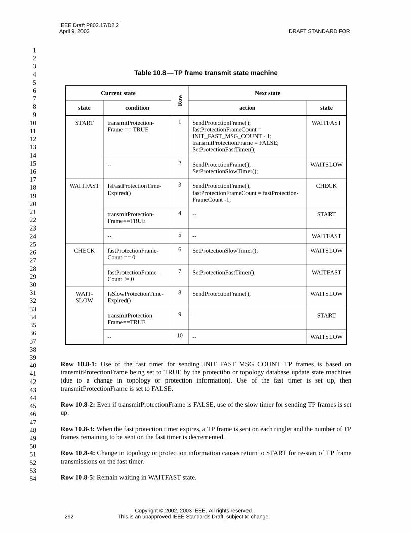
IEEE Draft P802.17/D2.2April 9, 2003 DRAFT STANDARD FOR
Copyright © 2002, 2003 IEEE. All rights reserved.292 This is an unapproved IEEE Standards Draft, subject to change.
123456789
101112131415161718192021222324252627282930313233343536373839404142434445464748495051525354
Row 10.8-1: Use of the fast timer for sending INIT_FAST_MSG_COUNT TP frames is based ontransmitProtectionFrame being set to TRUE by the protection or topology database update state machines(due to a change in topology or protection information). Use of the fast timer is set up, thentransmitProtectionFrame is set to FALSE.
Row 10.8-2: Even if transmitProtectionFrame is FALSE, use of the slow timer for sending TP frames is setup.
Row 10.8-3: When the fast protection timer expires, a TP frame is sent on each ringlet and the number of TPframes remaining to be sent on the fast timer is decremented.
Row 10.8-4: Change in topology or protection information causes return to START for re-start of TP frametransmissions on the fast timer.
Row 10.8-5: Remain waiting in WAITFAST state.
Table 10.8—TP frame transmit state machine
Current state
Row
Next state
state condition action state
START transmitProtection-Frame == TRUE
1 SendProtectionFrame();fastProtectionFrameCount =INIT_FAST_MSG_COUNT - 1;transmitProtectionFrame = FALSE;SetProtectionFastTimer();
WAITFAST
-- 2 SendProtectionFrame();SetProtectionSlowTimer();
WAITSLOW
WAITFAST IsFastProtectionTime-Expired()
3 SendProtectionFrame();fastProtectionFrameCount = fastProtection-FrameCount -1;
CHECK
transmitProtection-Frame==TRUE
4 -- START
-- 5 -- WAITFAST
CHECK fastProtectionFrame-Count == 0
6 SetProtectionSlowTimer(); WAITSLOW
fastProtectionFrame-Count != 0
7 SetProtectionFastTimer(); WAITFAST
WAIT-SLOW
IsSlowProtectionTime-Expired()
8 SendProtectionFrame(); WAITSLOW
transmitProtection-Frame==TRUE
9 -- START
-- 10 -- WAITSLOW

IEEE Draft P802.17/D2.2RESILIENT PACKET RING (RPR) April 9, 2003
Copyright © 2002, 2003 IEEE. All rights reserved.This is an unapproved IEEE Standards Draft, subject to change. 293
123456789101112131415161718192021222324252627282930313233343536373839404142434445464748495051525354
Row 10.8-6: INIT_FAST_MSG_COUNT TP frames have been sent (on each ringlet) on the fast timer, sonow the slow timer will be used for subsequent transmissions.
Row 10.8-7: INIT_FAST_MSG_COUNT TP frames have not yet been sent (on each ringlet) on the fasttimer, so the fast timer will be used for the next transmission.
Row 10.8-8: When the slow protection timer expires, a TP frame is sent on each ringlet.
Row 10.8-9: Change in topology or protection information causes return to START for re-start of TP frametransmissions on the fast timer.
Row 10.8-10: Remain waiting in WAITSLOW state.
10.9.2 Receive
The receipt of this frame on either ringlet from any station causes the MAC control sublayer to update itscurrent local topology image, as long as the sequence number check has passed. The sequence number checkis described in the flow chart shown in Figure 10.14.
Figure 10.14—Flow chart for sequence number check
Is message from newstation on ring?
No
Yes
ProtectionMessage is
received
discard theprotectionmessage
store sequencenumber for new
station and acceptthe protectionmessage for
further processing
Is sequencenumber unequal tostored sequencenumber for the
station?
Yes
store sequencenumber for station
and accept theprotection
message forfurther processing
No

IEEE Draft P802.17/D2.2April 9, 2003 DRAFT STANDARD FOR
Copyright © 2002, 2003 IEEE. All rights reserved.294 This is an unapproved IEEE Standards Draft, subject to change.
123456789
101112131415161718192021222324252627282930313233343536373839404142434445464748495051525354
The sequence number is used to enable stations to determine that the contents of a TP frame received from agiven source station has changed. If the sequence number on the received TP frame is different from thesequence number stored for the source station, then the TP frame is accepted for further processing.
The sequence number stored for a station is cleared when the entry for the station in the topology database ismarked invalid or cleared from the database.
The maximum value of the 6-bit sequence number field is MAX_SEQNUM, which equals 63.
In addition, the following contents of the TP frame are made available to the protection state machinerunning on each side of the station:
a) sa (source address)b) ttl (time to live)c) ri (ringlet identifier)d) wscw (wrap status code, west)e) wsce (wrap status code, east)f) prtw (protection request type, west)g) prte (protection request type, east)h) wp (wrap preferences)
The protection state machine differentiates received TP frames into two types. One type is those received onthe “short” path from the neighbor station directly connected to the interface on which the protection statemachine is running. These frames are used, for example, in unwrapping scenarios when a span is comingback into operation. The criteria for a frame to be considered a short path frame from the neighbor stationare shown in Figure 10.15.
All other TP frames are used to determine if protection conditions such as manual switch or wait to restoreare preempted by protection conditions reported from elsewhere on the ring.
Editors’ Notes: To be removed prior to final publication.
Flow chart will be modified to FrameMaker format in an upcoming version of the draft.
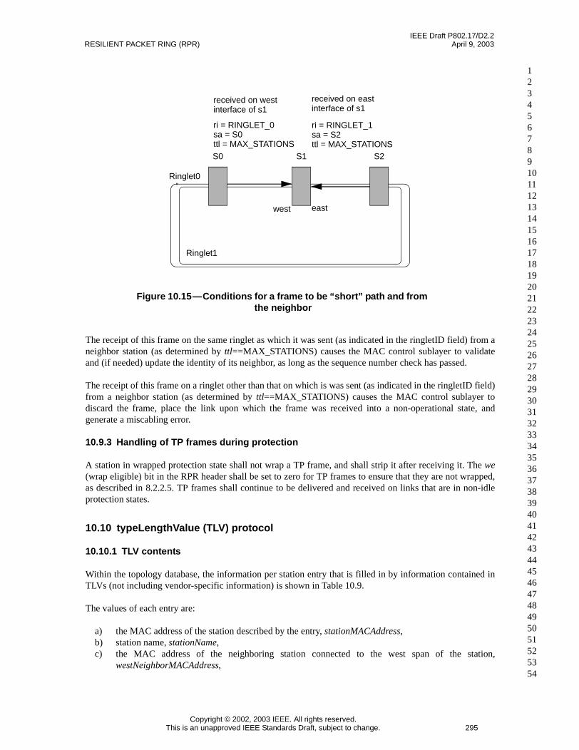
IEEE Draft P802.17/D2.2RESILIENT PACKET RING (RPR) April 9, 2003
Copyright © 2002, 2003 IEEE. All rights reserved.This is an unapproved IEEE Standards Draft, subject to change. 295
123456789101112131415161718192021222324252627282930313233343536373839404142434445464748495051525354
The receipt of this frame on the same ringlet as which it was sent (as indicated in the ringletID field) from aneighbor station (as determined by ttl==MAX_STATIONS) causes the MAC control sublayer to validateand (if needed) update the identity of its neighbor, as long as the sequence number check has passed.
The receipt of this frame on a ringlet other than that on which is was sent (as indicated in the ringletID field)from a neighbor station (as determined by ttl==MAX_STATIONS) causes the MAC control sublayer todiscard the frame, place the link upon which the frame was received into a non-operational state, andgenerate a miscabling error.
10.9.3 Handling of TP frames during protection
A station in wrapped protection state shall not wrap a TP frame, and shall strip it after receiving it. The we(wrap eligible) bit in the RPR header shall be set to zero for TP frames to ensure that they are not wrapped,as described in 8.2.2.5. TP frames shall continue to be delivered and received on links that are in non-idleprotection states.
10.10 typeLengthValue (TLV) protocol
10.10.1 TLV contents
Within the topology database, the information per station entry that is filled in by information contained inTLVs (not including vendor-specific information) is shown in Table 10.9.
The values of each entry are:
a) the MAC address of the station described by the entry, stationMACAddress,b) station name, stationName,c) the MAC address of the neighboring station connected to the west span of the station,
westNeighborMACAddress,
Figure 10.15—Conditions for a frame to be “short” path and fromthe neighbor
S0 S1 S2
Ringlet0
Ringlet1
west east
ri = RINGLET_0sa = S0ttl = MAX_STATIONS
ri = RINGLET_1sa = S2ttl = MAX_STATIONS
received on westinterface of s1
received on eastinterface of s1

IEEE Draft P802.17/D2.2April 9, 2003 DRAFT STANDARD FOR
Copyright © 2002, 2003 IEEE. All rights reserved.296 This is an unapproved IEEE Standards Draft, subject to change.
123456789
101112131415161718192021222324252627282930313233343536373839404142434445464748495051525354
d) the MAC address of the neighboring station connected to the east span of the station,eastNeighborMACAddress,
e) the station weight on ringlet0, ringlet0Weight,f) the station weight on ringlet1, ringlet1Weight,g) the reserved subclassA0 bandwidth on ringlet0, ringlet0ResBW,h) the reserved subclassA0 bandwidth on ringlet1, ringlet1ResBW.
Some rules related to updates of the topology database resulting from TLV frames are:
a) The topology database does not age stored information from TLV frames.b) When a TLV frame of a given type is received, all stored information contained in this type of TLV
frame is replaced.c) All TLV information received from station forms part of the topology database entry for that station.
10.10.2 TLV frame format
The TLV frame is a variable length frame. The TLV frame is not used for discovery of the physical topologyof the ring, but rather is used to convey additional information that needs to be reported by a station to therest of the ring on a slower timeframe, such as reserved bandwidth configuration information. The TLVframe is used for reporting changes in station status that are not as time critical as those reported in the TPframe.
Table 10.9—TLV contents in topology and status database
local MAC stationname
westneighbor's
MAC
eastneighbor's
MAC
ringlet0stationweight
ringlet1stationweight
ringlet0reserved
sub-classA0 band-width
ringlet1reserved
sub-classA0 band-width
00-10-A4-97-A8-DE
LosAngeles
00-10-A4-97-A8-EF
00-10-A4-97-A8-BD
1 5 50 40
00-10-A4-97-A8-EF
Denver 00-10-A4-97-A8-AC
00-10-A4-97-A8-DE
3 3 100 80
00-10-A4-97-A8-AC
Seattle 00-10-A4-97-A8-BD
00-10-A4-97-A8-EF
5 1 150 120
00-10-A4-97-A8-BD
Portland 00-10-A4-97-A8-DE
00-10-A4-97-A8-AC
1 5 200 160
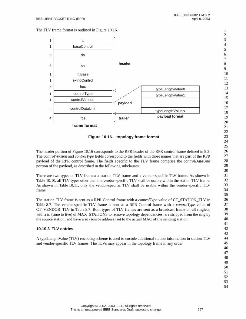
IEEE Draft P802.17/D2.2RESILIENT PACKET RING (RPR) April 9, 2003
Copyright © 2002, 2003 IEEE. All rights reserved.This is an unapproved IEEE Standards Draft, subject to change. 297
123456789101112131415161718192021222324252627282930313233343536373839404142434445464748495051525354
The TLV frame format is outlined in Figure 10.16.
The header portion of Figure 10.16 corresponds to the RPR header of the RPR control frame defined in 8.3.The controlVersion and controlType fields correspond to the fields with those names that are part of the RPRpayload of the RPR control frame. The fields specific to the TLV frame comprise the controlDataUnitportion of the payload, as described in the following subclauses.
There are two types of TLV frames: a station TLV frame and a vendor-specific TLV frame. As shown inTable 10.10, all TLV types other than the vendor-specific TLV shall be usable within the station TLV frame.As shown in Table 10.11, only the vendor-specific TLV shall be usable within the vendor-specific TLVframe.
The station TLV frame is sent as a RPR Control frame with a controlType value of CT_STATION_TLV inTable 8.7. The vendor-specific TLV frame is sent as a RPR Control frame with a controlType value ofCT_VENDOR_TLV in Table 8.7. Both types of TLV frames are sent as a broadcast frame on all ringlets,with a ttl (time to live) of MAX_STATIONS to remove topology dependencies, are stripped from the ring bythe source station, and have a sa (source address) set to the actual MAC of the sending station.
10.10.3 TLV entries
A typeLengthValue (TLV) encoding scheme is used to encode additional station information in station TLVand vendor-specific TLV frames. The TLVs may appear in the topology frame in any order.
Figure 10.16—topology frame format
1 baseControl
6 da
header
trailer payload format
1 ttl
6 sa
1 extndControl
1 ttlBase
n controlDataUnit
4 fcs
frame format
typeLengthValue1
typeLengthValue0
...
typeLengthValueN
payload
2 hec
1 controlVersion
1 controlType

IEEE Draft P802.17/D2.2April 9, 2003 DRAFT STANDARD FOR
Copyright © 2002, 2003 IEEE. All rights reserved.298 This is an unapproved IEEE Standards Draft, subject to change.
123456789
101112131415161718192021222324252627282930313233343536373839404142434445464748495051525354
The general format of a TLV is shown in Figure 10.17.
The 6-bit res1 field shall be reserved. The 10-bit type field specifies the TLV type, as specified inTable 10.10. The 6-bit res2 field shall be reserved. The 10-bit length field specifies the length of thefollowing typeDependent value information (shown in Table 10.10 and in Table 10.11), in bytes. The lengthof any typeDependent information shall be less than 1024 bytes.
Table 10.10—type encoding for station TLV frame
Value Name Size subclause Description
0 — — — Reserved
1 TLV_WEIGHT 2 10.10.4.1 Weights of stations on each ringlet
2 TLV_STATION_BW 4 10.10.4.2 Total reserved classA0 bandwidth (per ringlet)
3 TLV_NEIGHBOR 12 10.10.4.3 Neighbor address
4 TLV_STATION_NAME 255 10.10.4.4 Station name (an ASCII string)
5-1023 — — — Reserved
NOTES1—N is the number of other stations (one less than the total stations)2—S is the number of characters in the character string
Table 10.11—type encoding for vendor-specific TLV frame
Value Name Size subclause Description
0-5 — — — Reserved
6 TLV_VENDOR_SPEC 8+D 10.10.4.5 Nonstandard values (possibly vendor dependent)
8-1023 — — — Reserved
NOTE1—D is the number of dependent data bytes
Figure 10.17—typeLengthValue format
typeDependent[length]
res1 type res2 length4

IEEE Draft P802.17/D2.2RESILIENT PACKET RING (RPR) April 9, 2003
Copyright © 2002, 2003 IEEE. All rights reserved.This is an unapproved IEEE Standards Draft, subject to change. 299
123456789101112131415161718192021222324252627282930313233343536373839404142434445464748495051525354
10.10.4 Defined TLV encodings
The following subclauses define the TLV encodings supported by this standard. Any other type values arereserved.
10.10.4.1 Weight TLV
The weight TLV encodes the station weight in each ringlet. If a station has a weight not equal to 1 on eitherringlet, it shall advertise the weight. If a weight TLV is not included in the station TLV messages sent by agiven source station, then it is assumed that the station’s weight on each ringlet is equal to 1.
The weight TLV is identified by its distinctive type=TLV_WEIGHT value (see 10.10.3); its payload consistsof two classC weight parameters, as illustrated in Figure 10.18.
The source of the information contained in the weight TLV is the station weight per ringlet described in9.3.8. These parameters are configurable per station, and are reported to all other stations on the RPR ringusing the weight TLV. The consumer of the information contained in the weight TLV is the fairness module,that needs this information to compute the sum of the weights of active stations in 9.1.17.3.
10.10.4.1.1 type
The type field is set to TLV_WEIGHT.
10.10.4.1.2 length
The length field is set to the size corresponding to TLV_WEIGHT in Table 10.10.
10.10.4.1.3 Payload format
The format for the payload of the Weight TLV is shown in Figure 10.18.
The 8-bit ringlet0Weight and 8-bit ringlet1Weight fields specify the weight of the station on ringlet0 andringlet1 respectively.
10.10.4.2 Station bandwidth TLV
The station bandwidth TLV encodes the reserved subclassA0 bandwidth on the transmit direction on eachringlet used by the source station, and is mandatory. The station bandwidth TLV is identified by itsdistinctive type=TLV_STATION_BW value (see 10.10.3); its payload consists of two subclassA0 bandwidthparameters, as illustrated in Figure 10.19.
The source of the information contained in the station bandwidth TLV is the subclassA0 bandwidth reservedby the sending station for its transmissions on each ringlet. This reservation is made through configuration.These parameters are reported to all other stations on the RPR ring using this TLV. Each station then sums
Figure 10.18—Weight TLV payload format
ringlet1Weightringlet0Weight2
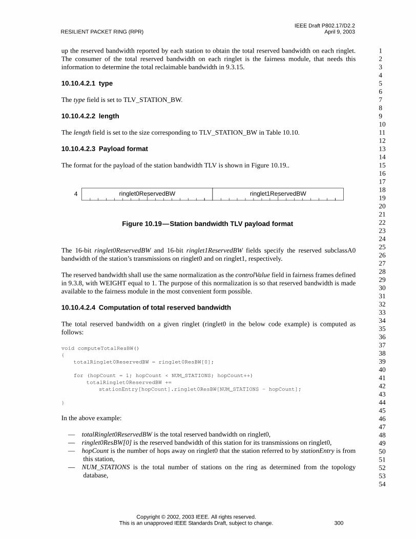
IEEE Draft P802.17/D2.2RESILIENT PACKET RING (RPR) April 9, 2003
Copyright © 2002, 2003 IEEE. All rights reserved.This is an unapproved IEEE Standards Draft, subject to change. 300
123456789101112131415161718192021222324252627282930313233343536373839404142434445464748495051525354
up the reserved bandwidth reported by each station to obtain the total reserved bandwidth on each ringlet.The consumer of the total reserved bandwidth on each ringlet is the fairness module, that needs thisinformation to determine the total reclaimable bandwidth in 9.3.15.
10.10.4.2.1 type
The type field is set to TLV_STATION_BW.
10.10.4.2.2 length
The length field is set to the size corresponding to TLV_STATION_BW in Table 10.10.
10.10.4.2.3 Payload format
The format for the payload of the station bandwidth TLV is shown in Figure 10.19..
The 16-bit ringlet0ReservedBW and 16-bit ringlet1ReservedBW fields specify the reserved subclassA0bandwidth of the station’s transmissions on ringlet0 and on ringlet1, respectively.
The reserved bandwidth shall use the same normalization as the controlValue field in fairness frames definedin 9.3.8, with WEIGHT equal to 1. The purpose of this normalization is so that reserved bandwidth is madeavailable to the fairness module in the most convenient form possible.
10.10.4.2.4 Computation of total reserved bandwidth
The total reserved bandwidth on a given ringlet (ringlet0 in the below code example) is computed asfollows:
void computeTotalResBW(){
totalRinglet0ReservedBW = ringlet0ResBW[0];
for (hopCount = 1; hopCount < NUM_STATIONS; hopCount++)totalRinglet0ReservedBW +=
stationEntry[hopCount].ringlet0ResBW[NUM_STATIONS - hopCount];
}
In the above example:
— totalRinglet0ReservedBW is the total reserved bandwidth on ringlet0,— ringlet0ResBW[0] is the reserved bandwidth of this station for its transmissions on ringlet0,— hopCount is the number of hops away on ringlet0 that the station referred to by stationEntry is from
this station,— NUM_STATIONS is the total number of stations on the ring as determined from the topology
database,
Figure 10.19—Station bandwidth TLV payload format
ringlet0ReservedBW ringlet1ReservedBW4
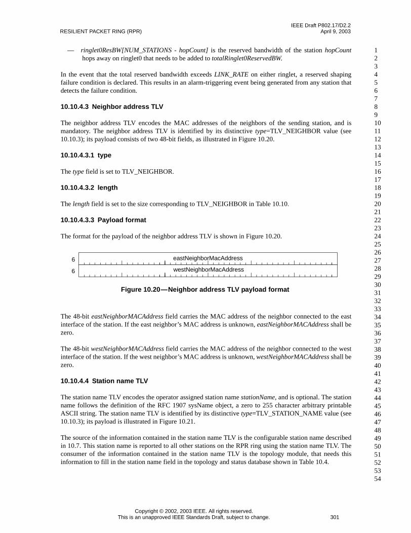
IEEE Draft P802.17/D2.2RESILIENT PACKET RING (RPR) April 9, 2003
Copyright © 2002, 2003 IEEE. All rights reserved.This is an unapproved IEEE Standards Draft, subject to change. 301
123456789101112131415161718192021222324252627282930313233343536373839404142434445464748495051525354
— ringlet0ResBW[NUM_STATIONS - hopCount] is the reserved bandwidth of the station hopCounthops away on ringlet0 that needs to be added to totalRinglet0ReservedBW.
In the event that the total reserved bandwidth exceeds LINK_RATE on either ringlet, a reserved shapingfailure condition is declared. This results in an alarm-triggering event being generated from any station thatdetects the failure condition.
10.10.4.3 Neighbor address TLV
The neighbor address TLV encodes the MAC addresses of the neighbors of the sending station, and ismandatory. The neighbor address TLV is identified by its distinctive type=TLV_NEIGHBOR value (see10.10.3); its payload consists of two 48-bit fields, as illustrated in Figure 10.20.
10.10.4.3.1 type
The type field is set to TLV_NEIGHBOR.
10.10.4.3.2 length
The length field is set to the size corresponding to TLV_NEIGHBOR in Table 10.10.
10.10.4.3.3 Payload format
The format for the payload of the neighbor address TLV is shown in Figure 10.20.
The 48-bit eastNeighborMACAddress field carries the MAC address of the neighbor connected to the eastinterface of the station. If the east neighbor’s MAC address is unknown, eastNeighborMACAddress shall bezero.
The 48-bit westNeighborMACAddress field carries the MAC address of the neighbor connected to the westinterface of the station. If the west neighbor’s MAC address is unknown, westNeighborMACAddress shall bezero.
10.10.4.4 Station name TLV
The station name TLV encodes the operator assigned station name stationName, and is optional. The stationname follows the definition of the RFC 1907 sysName object, a zero to 255 character arbitrary printableASCII string. The station name TLV is identified by its distinctive type=TLV_STATION_NAME value (see10.10.3); its payload is illustrated in Figure 10.21.
The source of the information contained in the station name TLV is the configurable station name describedin 10.7. This station name is reported to all other stations on the RPR ring using the station name TLV. Theconsumer of the information contained in the station name TLV is the topology module, that needs thisinformation to fill in the station name field in the topology and status database shown in Table 10.4.
Figure 10.20—Neighbor address TLV payload format
eastNeighborMacAddress
westNeighborMacAddress
6
6

IEEE Draft P802.17/D2.2RESILIENT PACKET RING (RPR) April 9, 2003
Copyright © 2002, 2003 IEEE. All rights reserved.This is an unapproved IEEE Standards Draft, subject to change. 302
123456789101112131415161718192021222324252627282930313233343536373839404142434445464748495051525354
10.10.4.4.1 type
The type field is set to TLV_STATION_NAME.
10.10.4.4.2 length
The length field is set to the size corresponding to TLV_STATION_NAME in Table 10.10.
10.10.4.4.3 Payload format
The format for the payload of the station name TLV is shown in Figure 10.21.
The character[0] through character[254] fields identify the first through last ASCII characterscorresponding to the station’s name (a null-character termination is not provided). The acceptable subset ofASCII characters supported is the set defined in IEEE 1212, with the exception that only characters of spaceand above are supported.
10.10.4.5 Vendor specific TLV
The Vendor specific TLV encodes the vendor specific information of the station, and is optional. This TLV isidentified by its distinctive controlType=CT_VENDOR_TLV and its distinctivetype=TLV_VENDOR_SPEC value (see 10.10.3); its payload is illustrated in Figure 10.22.
The source of the information contained in the vendor specific TLV is a collection of vendor specificparameters. This information is reported to all other stations on the RPR ring using the vendor specific TLV.The consumer of the information contained in the vendor specific TLV depends on the parameters and isoutside the scope of this standard.
10.10.4.5.1 type
The type field is set to TLV_VENDOR_SPEC.
10.10.4.5.2 length
The length field is set to the size corresponding to TLV_VENDOR_SPEC in Table 10.10.
Figure 10.21—Station name TLV payload format
character[0]
…
character[1]
character[254]
1
1
1
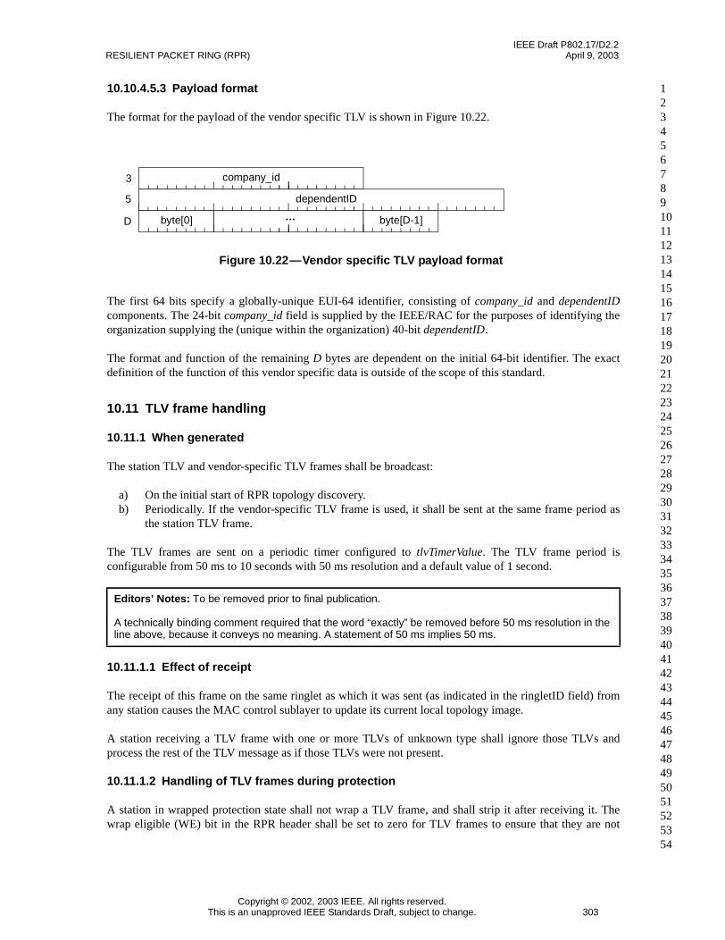
IEEE Draft P802.17/D2.2RESILIENT PACKET RING (RPR) April 9, 2003
Copyright © 2002, 2003 IEEE. All rights reserved.This is an unapproved IEEE Standards Draft, subject to change. 303
123456789101112131415161718192021222324252627282930313233343536373839404142434445464748495051525354
10.10.4.5.3 Payload format
The format for the payload of the vendor specific TLV is shown in Figure 10.22.
The first 64 bits specify a globally-unique EUI-64 identifier, consisting of company_id and dependentIDcomponents. The 24-bit company_id field is supplied by the IEEE/RAC for the purposes of identifying theorganization supplying the (unique within the organization) 40-bit dependentID.
The format and function of the remaining D bytes are dependent on the initial 64-bit identifier. The exactdefinition of the function of this vendor specific data is outside of the scope of this standard.
10.11 TLV frame handling
10.11.1 When generated
The station TLV and vendor-specific TLV frames shall be broadcast:
a) On the initial start of RPR topology discovery.b) Periodically. If the vendor-specific TLV frame is used, it shall be sent at the same frame period as
the station TLV frame.
The TLV frames are sent on a periodic timer configured to tlvTimerValue. The TLV frame period isconfigurable from 50 ms to 10 seconds with 50 ms resolution and a default value of 1 second.
10.11.1.1 Effect of receipt
The receipt of this frame on the same ringlet as which it was sent (as indicated in the ringletID field) fromany station causes the MAC control sublayer to update its current local topology image.
A station receiving a TLV frame with one or more TLVs of unknown type shall ignore those TLVs andprocess the rest of the TLV message as if those TLVs were not present.
10.11.1.2 Handling of TLV frames during protection
A station in wrapped protection state shall not wrap a TLV frame, and shall strip it after receiving it. Thewrap eligible (WE) bit in the RPR header shall be set to zero for TLV frames to ensure that they are not
Editors’ Notes: To be removed prior to final publication.
A technically binding comment required that the word “exactly” be removed before 50 ms resolution in theline above, because it conveys no meaning. A statement of 50 ms implies 50 ms.
Figure 10.22—Vendor specific TLV payload format
dependentID
company_id
byte[D-1]byte[0] …
3
D
5

IEEE Draft P802.17/D2.2RESILIENT PACKET RING (RPR) April 9, 2003
Copyright © 2002, 2003 IEEE. All rights reserved.This is an unapproved IEEE Standards Draft, subject to change. 304
123456789101112131415161718192021222324252627282930313233343536373839404142434445464748495051525354
wrapped, as described in 8.2.2.5. TLV frames shall continue to be delivered and received on links that are innon-idle protection states.
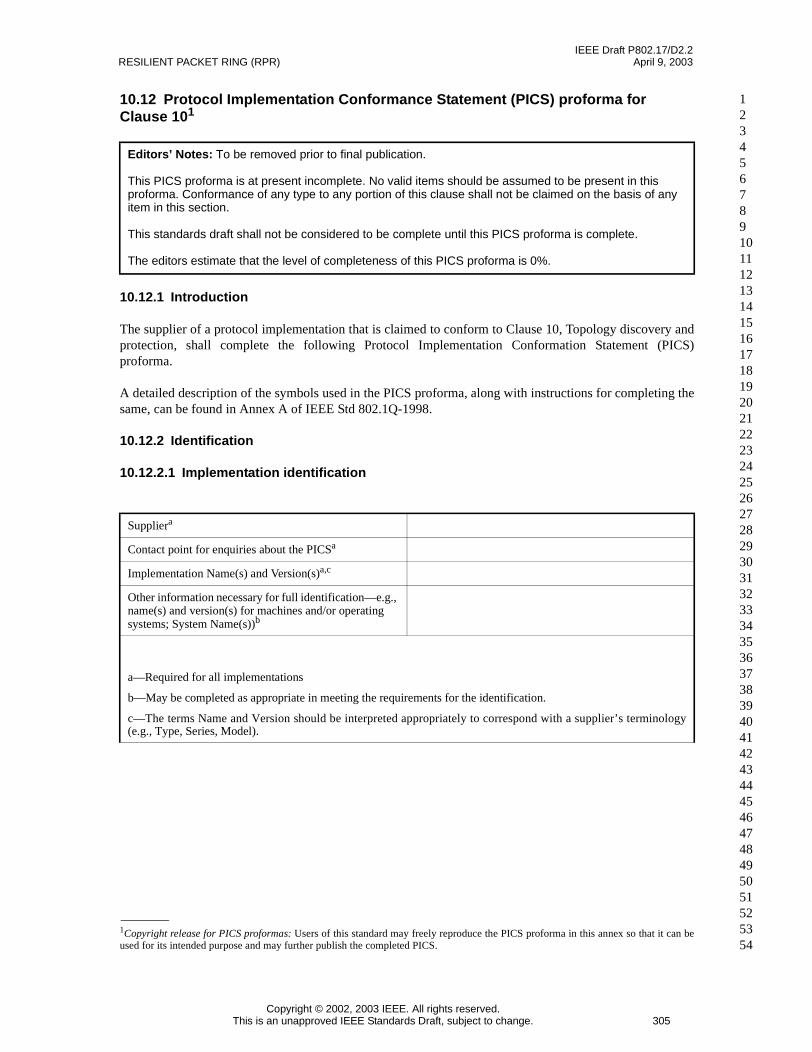
IEEE Draft P802.17/D2.2RESILIENT PACKET RING (RPR) April 9, 2003
Copyright © 2002, 2003 IEEE. All rights reserved.This is an unapproved IEEE Standards Draft, subject to change. 305
123456789101112131415161718192021222324252627282930313233343536373839404142434445464748495051525354
10.12 Protocol Implementation Conformance Statement (PICS) proforma forClause 101
10.12.1 Introduction
The supplier of a protocol implementation that is claimed to conform to Clause 10, Topology discovery andprotection, shall complete the following Protocol Implementation Conformation Statement (PICS)proforma.
A detailed description of the symbols used in the PICS proforma, along with instructions for completing thesame, can be found in Annex A of IEEE Std 802.1Q-1998.
10.12.2 Identification
10.12.2.1 Implementation identification
Editors’ Notes: To be removed prior to final publication.
This PICS proforma is at present incomplete. No valid items should be assumed to be present in thisproforma. Conformance of any type to any portion of this clause shall not be claimed on the basis of anyitem in this section.
This standards draft shall not be considered to be complete until this PICS proforma is complete.
The editors estimate that the level of completeness of this PICS proforma is 0%.
1Copyright release for PICS proformas: Users of this standard may freely reproduce the PICS proforma in this annex so that it can beused for its intended purpose and may further publish the completed PICS.
Suppliera
Contact point for enquiries about the PICSa
Implementation Name(s) and Version(s)a,c
Other information necessary for full identification—e.g.,name(s) and version(s) for machines and/or operatingsystems; System Name(s))b
a—Required for all implementations
b—May be completed as appropriate in meeting the requirements for the identification.
c—The terms Name and Version should be interpreted appropriately to correspond with a supplier’s terminology(e.g., Type, Series, Model).
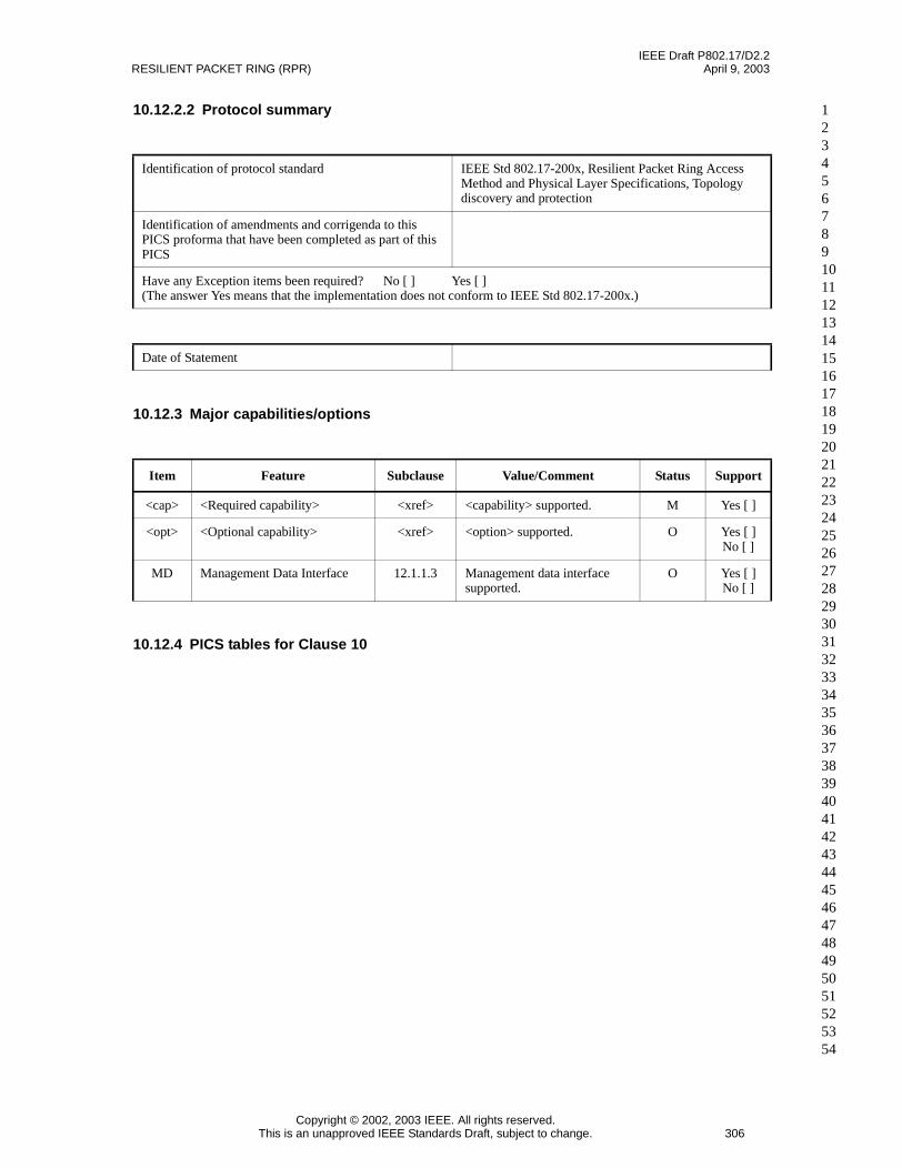
IEEE Draft P802.17/D2.2RESILIENT PACKET RING (RPR) April 9, 2003
Copyright © 2002, 2003 IEEE. All rights reserved.This is an unapproved IEEE Standards Draft, subject to change. 306
123456789101112131415161718192021222324252627282930313233343536373839404142434445464748495051525354
10.12.2.2 Protocol summary
10.12.3 Major capabilities/options
10.12.4 PICS tables for Clause 10
Identification of protocol standard IEEE Std 802.17-200x, Resilient Packet Ring AccessMethod and Physical Layer Specifications, Topologydiscovery and protection
Identification of amendments and corrigenda to thisPICS proforma that have been completed as part of thisPICS
Have any Exception items been required? No [ ] Yes [ ](The answer Yes means that the implementation does not conform to IEEE Std 802.17-200x.)
Date of Statement
Item Feature Subclause Value/Comment Status Support
<cap> <Required capability> <xref> <capability> supported. M Yes [ ]
<opt> <Optional capability> <xref> <option> supported. O Yes [ ]No [ ]
MD Management Data Interface 12.1.1.3 Management data interfacesupported.
O Yes [ ]No [ ]


![In This Issue - cisco.com · way Protocol [IGP]), which maintains a complete mapping set for the current internal topology of the domain, together with the set of “best paths”](https://static.fdocuments.us/doc/165x107/5cce702688c99385278cca22/in-this-issue-ciscocom-way-protocol-igp-which-maintains-a-complete-mapping.jpg)