10 Testing · 10 Testing Gradation Sieving Decantation Sieve Analysis Test Fineness Modulus Sieve...
28
10 Testing Gradation Sieving Decantation Sieve Analysis Test Fineness Modulus Sieve Analysis for Dense Graded (Long Graded) Materials Deleterious Materials Deleterious Materials in Coarse Materials Deleterious Materials in Natural Sands Crushed Particles Flat and Elongated Particles Plastic Limit Total Moisture Content
Transcript of 10 Testing · 10 Testing Gradation Sieving Decantation Sieve Analysis Test Fineness Modulus Sieve...
10 Testing
Gradation
Sieving Decantation Sieve Analysis Test Fineness Modulus Sieve Analysis for Dense Graded (Long Graded) Materials Deleterious Materials
Deleterious Materials in Coarse Materials Deleterious Materials in Natural Sands Crushed Particles Flat and Elongated Particles Plastic Limit Total Moisture Content
10-1
CHAPTER TEN: TESTING
After obtaining and splitting the sample, the next step is to conduct the test. Uniform and consistent testing is required to remove variables in the total operation.
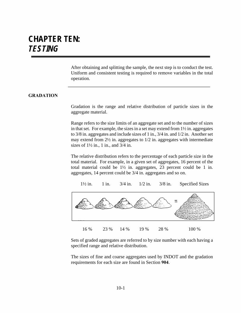
GRADATION Gradation is the range and relative distribution of particle sizes in the aggregate material. Range refers to the size limits of an aggregate set and to the number of sizes in that set. For example, the sizes in a set may extend from 1½ in. aggregates to 3/8 in. aggregates and include sizes of 1 in., 3/4 in. and 1/2 in. Another set may extend from 2½ in. aggregates to 1/2 in. aggregates with intermediate sizes of 1½ in., 1 in., and 3/4 in. The relative distribution refers to the percentage of each particle size in the total material. For example, in a given set of aggregates, 16 percent of the total material could be 1½ in. aggregates, 23 percent could be 1 in. aggregates, 14 percent could be 3/4 in. aggregates and so on. 1½ in. 1 in. 3/4 in. 1/2 in. 3/8 in. Specified Sizes
16 % 23 % 14 % 19 % 28 % 100 %
Sets of graded aggregates are referred to by size number with each having a specified range and relative distribution.
The sizes of fine and coarse aggregates used by INDOT and the gradation requirements for each size are found in Section 904.
10-2
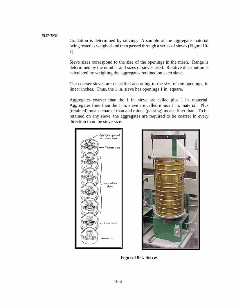
SIEVING Gradation is determined by sieving. A sample of the aggregate material being tested is weighed and then passed through a series of sieves (Figure 10-1).
Sieve sizes correspond to the size of the openings in the mesh. Range is determined by the number and sizes of sieves used. Relative distribution is calculated by weighing the aggregates retained on each sieve.
The coarser sieves are classified according to the size of the openings, in linear inches. Thus, the 1 in. sieve has openings 1 in. square.
Aggregates coarser than the 1 in. sieve are called plus 1 in. material. Aggregates finer than the 1 in. sieve are called minus 1 in. material. Plus (retained) means coarser than and minus (passing) means finer than. To be retained on any sieve, the aggregates are required to be coarser in every direction than the sieve size.
Figure 10-1. Sieves
10-3
DECANTATION
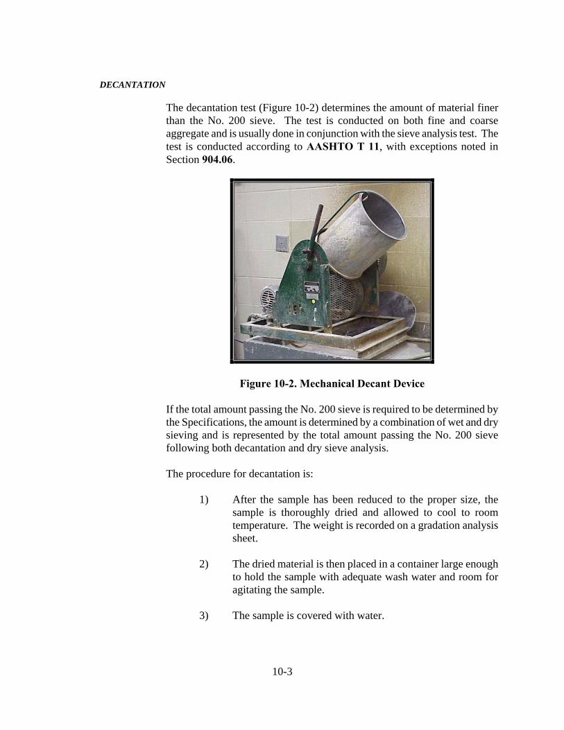
The decantation test (Figure 10-2) determines the amount of material finer than the No. 200 sieve. The test is conducted on both fine and coarse aggregate and is usually done in conjunction with the sieve analysis test. The test is conducted according to AASHTO T 11, with exceptions noted in Section 904.06.
Figure 10-2. Mechanical Decant Device
If the total amount passing the No. 200 sieve is required to be determined by the Specifications, the amount is determined by a combination of wet and dry sieving and is represented by the total amount passing the No. 200 sieve following both decantation and dry sieve analysis.
The procedure for decantation is:
1) After the sample has been reduced to the proper size, the
sample is thoroughly dried and allowed to cool to room temperature. The weight is recorded on a gradation analysis sheet.
2) The dried material is then placed in a container large enough
to hold the sample with adequate wash water and room for agitating the sample.
3) The sample is covered with water.
10-4
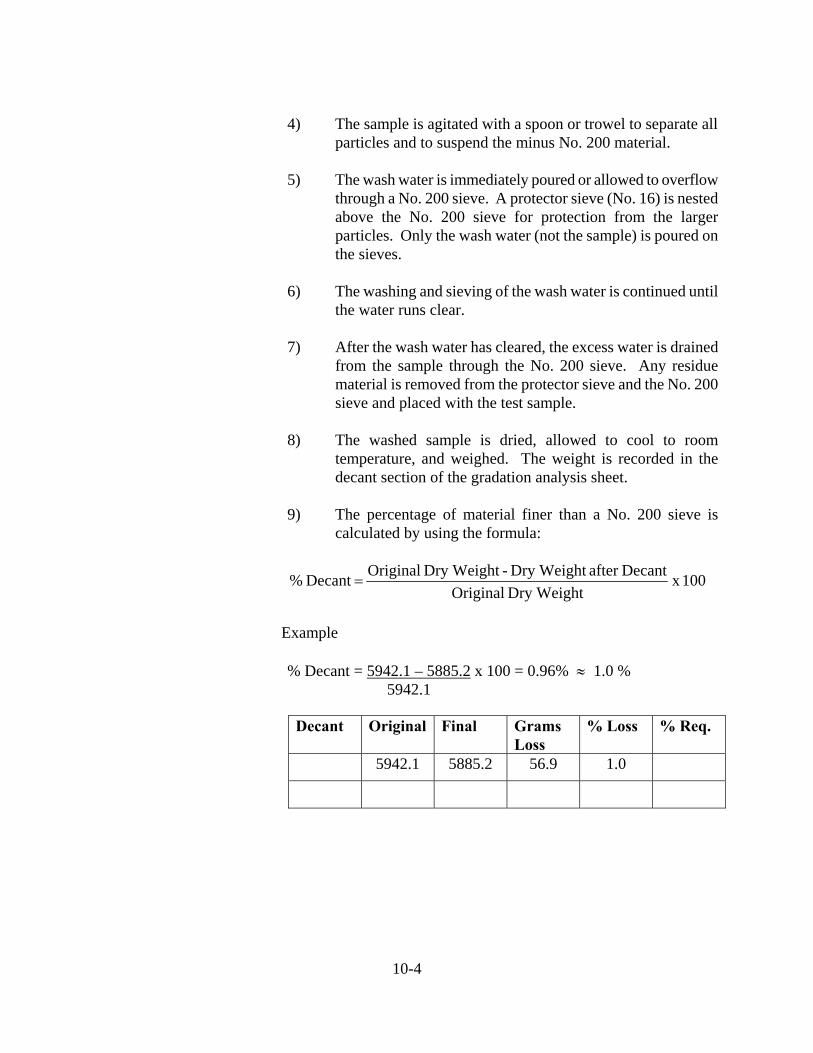
4) The sample is agitated with a spoon or trowel to separate all particles and to suspend the minus No. 200 material.
5) The wash water is immediately poured or allowed to overflow
through a No. 200 sieve. A protector sieve (No. 16) is nested above the No. 200 sieve for protection from the larger particles. Only the wash water (not the sample) is poured on the sieves.
6) The washing and sieving of the wash water is continued until
the water runs clear.
7) After the wash water has cleared, the excess water is drained from the sample through the No. 200 sieve. Any residue material is removed from the protector sieve and the No. 200 sieve and placed with the test sample.
8) The washed sample is dried, allowed to cool to room
temperature, and weighed. The weight is recorded in the decant section of the gradation analysis sheet.
9) The percentage of material finer than a No. 200 sieve is
calculated by using the formula:
100 x Dry Weight Original
Decantafter Dry Weight - Dry Weight Original Decant %
Example
% Decant = 5942.1 – 5885.2 x 100 = 0.96% 1.0 %
5942.1
Decant Original Final Grams Loss
% Loss % Req.
5942.1 5885.2 56.9 1.0
10-5
Sieve analysis is used primarily to determine the particle-size distribution or gradation of materials. The results are used to determine compliance with the applicable Specification requirements. The test is conducted on both the fine and coarse aggregates and is usually done in conjunction with the decantation test.
The sieve analysis for mineral filler is conducted in accordance with AASHTO T 37. Because of the very fine particle-size of mineral filler, this test requires washing the material over the required sieves. The sieve analysis for all other fine aggregates and all coarse aggregates is conducted in accordance with AASHTO T 27. Exceptions to AASHTO T 37 and AASHTO T 27 are listed in Section 904.06.
The procedure for the sieve analysis in accordance with AASHTO T 27 is as follows:
1) The dried (decanted) sample is placed in the top sieve of
properly nested sieves. The sieves are nested in sequence with the smallest sieve placed on the pan and stacked by increasing size.
2) The shaking time is required to be sufficient to ensure that the
sample is divided into fractional sizes. The actual shaking time is required to be determined in accordance with ITM 906. The following times are minimum for shakers used by the industry.
Coarse Aggregate, Size 9 or larger 5 Minutes Coarse Aggregate, Smaller than Size 9 10 Minutes Fine Aggregates 15 Minutes
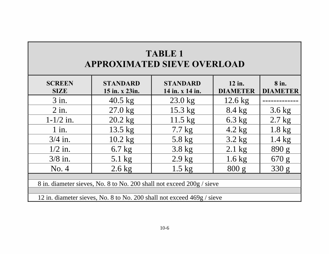
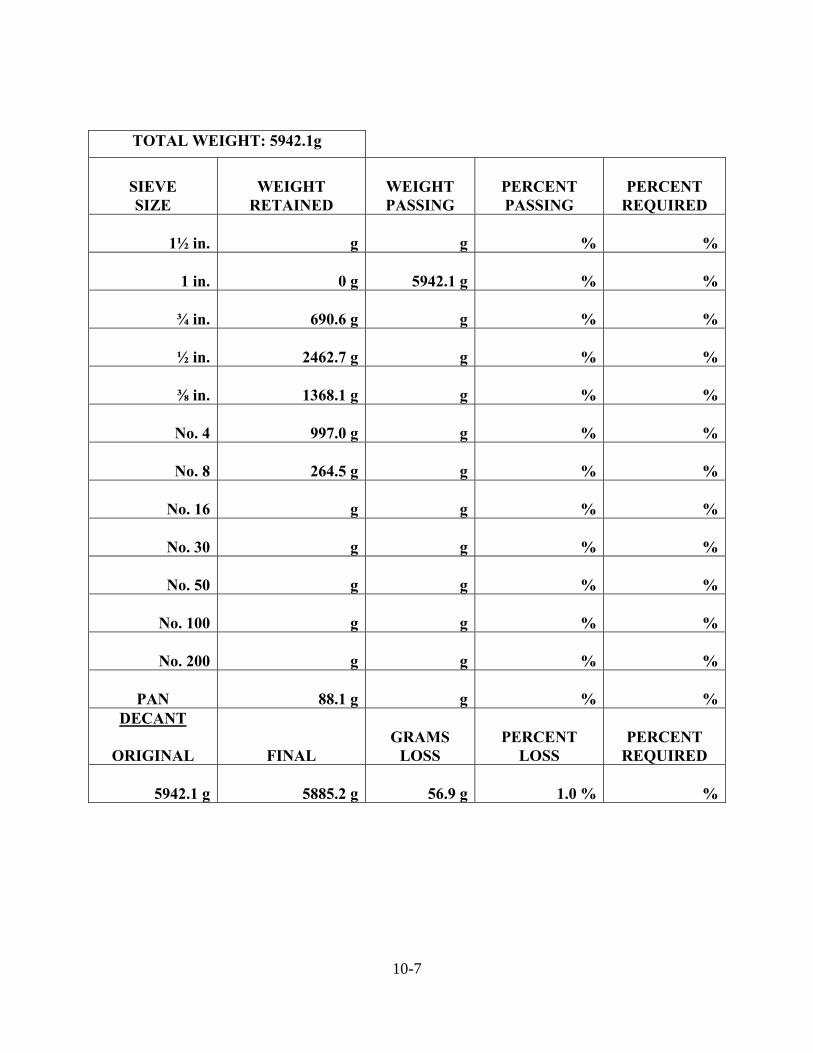
3) At the conclusion of sieving, the material retained on each
sieve is carefully transferred to a weigh pan and weighed. The weight retained of the material on each sieve is recorded on the Gradation Analysis sheet. The weight may not exceed the allowable amount on each sieve as indicated in Table 1.
The larger sieves (above the No. 16) are cleaned with a small trowel or piece of flat metal. The sieves between the No. 16 and No. 50 are cleaned with a wire brush. The sieves smaller than the No. 50 are cleaned with a soft bristle brush. Care is required to be taken not to damage the sieves.
10-6
TABLE 1 APPROXIMATED SIEVE OVERLOAD
SCREEN SIZE
STANDARD 15 in. x 23in.
STANDARD 14 in. x 14 in.
12 in. DIAMETER
8 in. DIAMETER
3 in. 40.5 kg 23.0 kg 12.6 kg -------------2 in. 27.0 kg 15.3 kg 8.4 kg 3.6 kg
1-1/2 in. 20.2 kg 11.5 kg 6.3 kg 2.7 kg 1 in. 13.5 kg 7.7 kg 4.2 kg 1.8 kg
3/4 in. 10.2 kg 5.8 kg 3.2 kg 1.4 kg 1/2 in. 6.7 kg 3.8 kg 2.1 kg 890 g 3/8 in. 5.1 kg 2.9 kg 1.6 kg 670 g No. 4 2.6 kg 1.5 kg 800 g 330 g
8 in. diameter sieves, No. 8 to No. 200 shall not exceed 200g / sieve
12 in. diameter sieves, No. 8 to No. 200 shall not exceed 469g / sieve
10-7
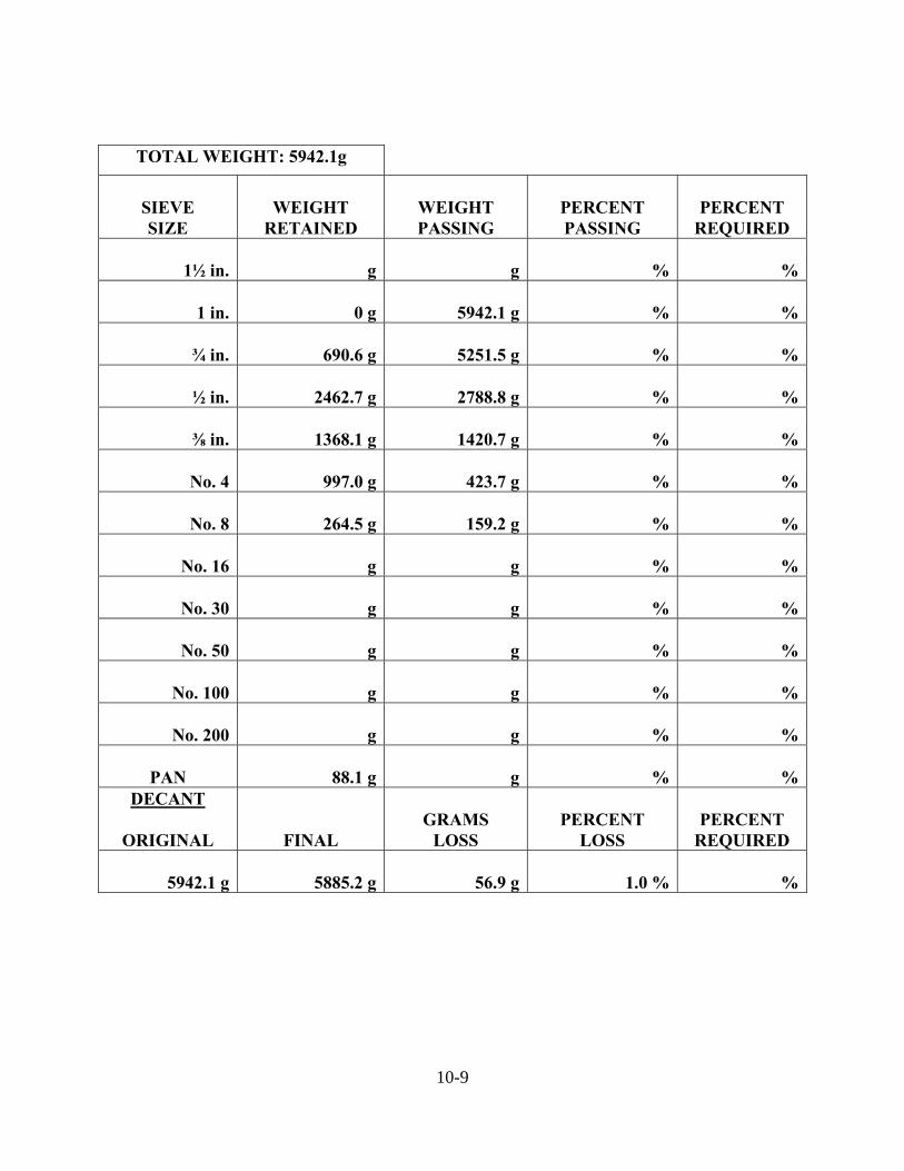
TOTAL WEIGHT: 5942.1g
SIEVE SIZE
WEIGHT
RETAINED
WEIGHT PASSING
PERCENT PASSING
PERCENT
REQUIRED
1½ in. g g
% %
1 in. 0 g 5942.1 g
% %
¾ in. 690.6 g g
% %
½ in. 2462.7 g g
% %
⅜ in. 1368.1 g g
% %
No. 4 997.0 g g
% %
No. 8 264.5 g g
% %
No. 16 g g
% %
No. 30 g g
% %
No. 50 g g
% %
No. 100 g g
% %
No. 200 g g
% %
PAN 88.1 g g
% %DECANT
ORIGINAL
FINAL
GRAMS
LOSS
PERCENT
LOSS
PERCENT
REQUIRED 5942.1 g 5885.2 g 56.9 g
1.0 % %
10-8
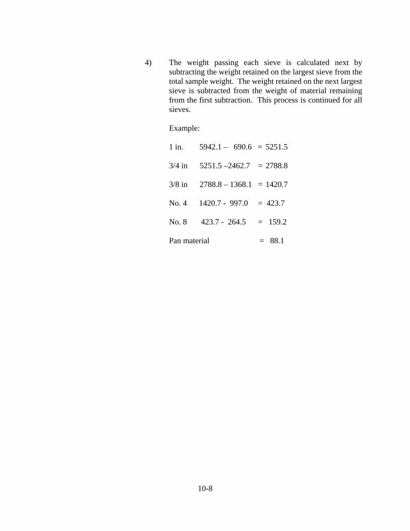
4) The weight passing each sieve is calculated next by subtracting the weight retained on the largest sieve from the total sample weight. The weight retained on the next largest sieve is subtracted from the weight of material remaining from the first subtraction. This process is continued for all sieves.
Example:
1 in. 5942.1 – 690.6 = 5251.5
3/4 in 5251.5 –2462.7 = 2788.8
3/8 in 2788.8 – 1368.1 = 1420.7
No. 4 1420.7 - 997.0 = 423.7
No. 8 423.7 - 264.5 = 159.2
Pan material = 88.1
10-9
TOTAL WEIGHT: 5942.1g
SIEVE SIZE
WEIGHT
RETAINED
WEIGHT PASSING
PERCENT PASSING
PERCENT
REQUIRED
1½ in. g g
% %
1 in. 0 g 5942.1 g
% %
¾ in. 690.6 g 5251.5 g
% %
½ in. 2462.7 g 2788.8 g
% %
⅜ in. 1368.1 g 1420.7 g
% %
No. 4 997.0 g 423.7 g
% %
No. 8 264.5 g 159.2 g
% %
No. 16 g g
% %
No. 30 g g
% %
No. 50 g g
% %
No. 100 g g
% %
No. 200 g g
% %
PAN 88.1 g g
% %DECANT
ORIGINAL
FINAL
GRAMS
LOSS
PERCENT
LOSS
PERCENT
REQUIRED 5942.1 g 5885.2 g 56.9 g
1.0 % %
10-10
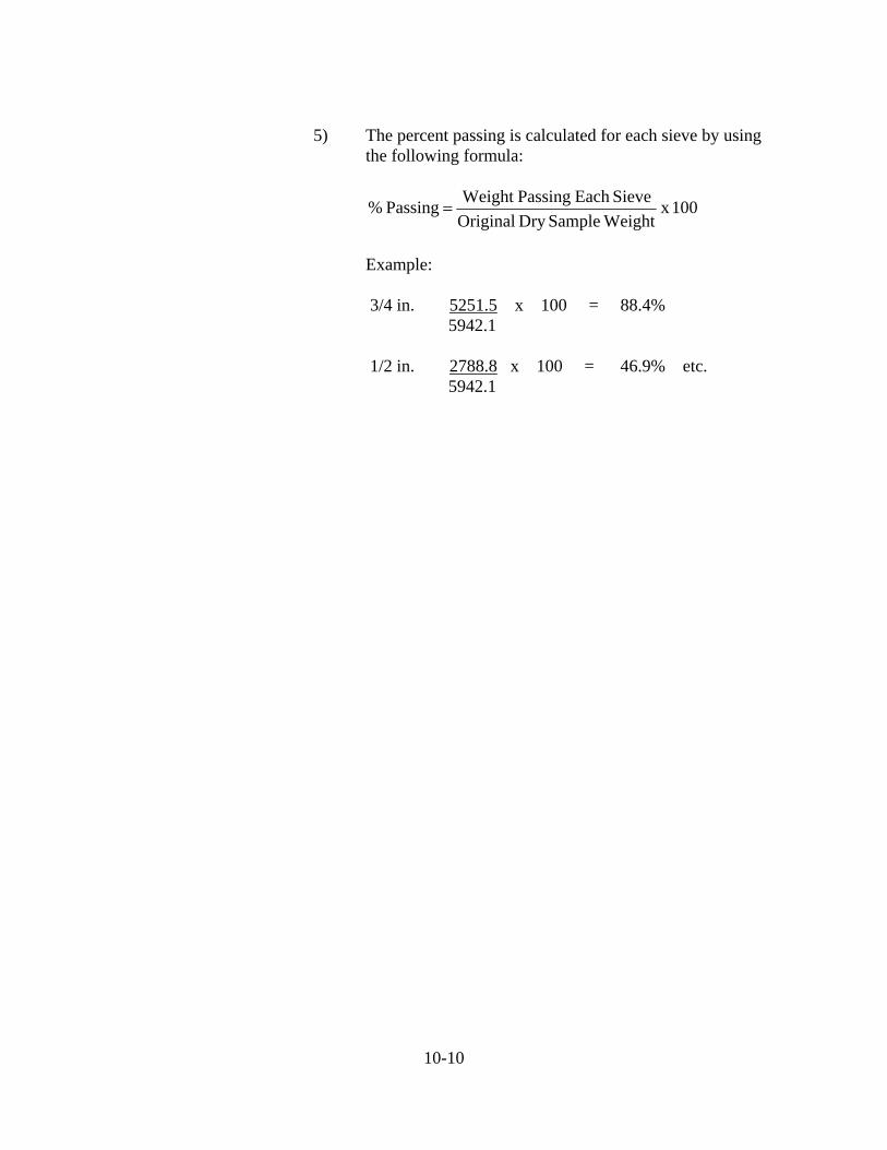
5) The percent passing is calculated for each sieve by using the following formula:
100 x WeightSampleDry Original
SieveEach PassingWeight Passing %
Example:
3/4 in. 5251.5 x 100 = 88.4%
5942.1
1/2 in. 2788.8 x 100 = 46.9% etc. 5942.1
10-11
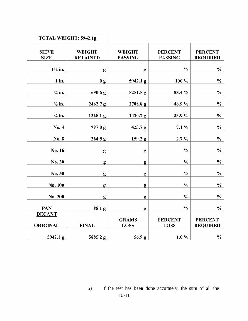
TOTAL WEIGHT: 5942.1g
SIEVE SIZE
WEIGHT
RETAINED
WEIGHT PASSING
PERCENT PASSING
PERCENT
REQUIRED
1½ in. g g
% %
1 in. 0 g 5942.1 g
100 % %
¾ in. 690.6 g 5251.5 g
88.4 % %
½ in. 2462.7 g 2788.8 g
46.9 % %
⅜ in. 1368.1 g 1420.7 g
23.9 % %
No. 4 997.0 g 423.7 g
7.1 % %
No. 8 264.5 g 159.2 g
2.7 % %
No. 16 g g
% %
No. 30 g g
% %
No. 50 g g
% %
No. 100 g g
% %
No. 200 g g
% %
PAN 88.1 g g
% %DECANT
ORIGINAL
FINAL
GRAMS
LOSS
PERCENT
LOSS
PERCENT
REQUIRED 5942.1 g 5885.2 g 56.9 g
1.0 % %
6) If the test has been done accurately, the sum of all the
10-12
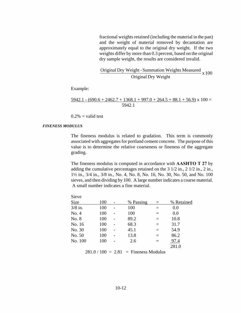
fractional weights retained (including the material in the pan) and the weight of material removed by decantation are approximately equal to the original dry weight. If the two weights differ by more than 0.3 percent, based on the original dry sample weight, the results are considered invalid.
100 x Dry Weight Original
Measured WeightsSummation - Dry Weight Original
Example:
5942.1 - (690.6 + 2462.7 + 1368.1 + 997.0 + 264.5 + 88.1 + 56.9) x 100 =
5942.1
0.2% = valid test
FINENESS MODULUS
The fineness modulus is related to gradation. This term is commonly associated with aggregates for portland cement concrete. The purpose of this value is to determine the relative coarseness or fineness of the aggregate grading. The fineness modulus is computed in accordance with AASHTO T 27 by adding the cumulative percentages retained on the 3 1/2 in., 2 1/2 in., 2 in., 1½ in., 3/4 in., 3/8 in., No. 4, No. 8, No. 16, No. 30, No. 50, and No. 100 sieves, and then dividing by 100. A large number indicates a coarse material. A small number indicates a fine material.
Sieve Size 100 - % Passing = % Retained 3/8 in. 100 - 100 = 0.0 No. 4 100 - 100 = 0.0 No. 8 100 - 89.2 = 10.8 No. 16 100 - 68.3 = 31.7 No. 30 100 - 45.1 = 54.9 No. 50 100 - 13.8 = 86.2 No. 100 100 - 2.6 = 97.4 281.0 281.0 / 100 = 2.81 = Fineness Modulus

10-13
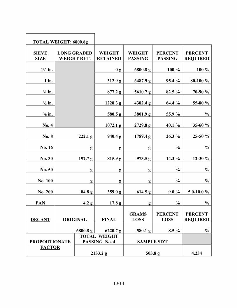
SIEVE ANALYSIS FOR DENSE GRADED (LONG GRADED) MATERIALS
Dense graded materials, such as compacted aggregates and some B borrows or subbase, consist of substantial quantities of material retained on and passing the No. 4 sieve.
The procedure for conducting a sieve analysis on a dense graded material is:
1) The entire sample is sieved and weighed in the same manner
as well-graded materials, except the smallest sieve is required to be the No. 4 sieve.
2) The portion of the sample passing the No. 4 sieve is weighed.
3) Using a sand sample splitter, the portion of the sample
passing the No. 4 sieve is reduced to approximately 500 grams.
4) The reduced sample is weighed and a proportionate factor is
determined by dividing the weight of the portion of the sample passing the No. 4 sieve by the weight of the reduced sample. For example, if the total weight of the portion of material passing the No. 4 sieve is 2221.4 grams and the reduced sample weight is 503.4 grams, the proportionate factor would be equal to 2221.4 grams divided by 503.4 grams, which equals 4.413.
5) The reduced sample is sieved for 15 minutes.
6) The material on each sieve is weighed and multiplied by the
proportionate factor. The calculated weight is recorded as the total weight of material retained on that sieve.
7) The calculations for percentage passing are completed as for
well-graded aggregates.
10-14
TOTAL WEIGHT: 6800.8g
SIEVE SIZE
LONG GRADED WEIGHT RET.
WEIGHT
RETAINED
WEIGHT PASSING
PERCENT PASSING
PERCENT
REQUIRED
1½ in.
0 g 6800.8 g
100 % 100 %
1 in. 312.9 g 6487.9 g
95.4 % 80-100 %
¾ in. 877.2 g 5610.7 g
82.5 % 70-90 %
½ in. 1228.3 g 4382.4 g
64.4 % 55-80 %
⅜ in. 580.5 g 3801.9 g
55.9 % %
No. 4 1072.1 g 2729.8 g
40.1 % 35-60 %
No. 8
222.1 g 940.4 g 1789.4 g
26.3 % 25-50 %
No. 16
g g g
% %
No. 30
192.7 g 815.9 g 973.5 g
14.3 % 12-30 %
No. 50
g g g
% %
No. 100
g g g
% %
No. 200
84.8 g 359.0 g 614.5 g
9.0 % 5.0-10.0 %
PAN
4.2 g 17.8 g g
% %
DECANT
ORIGINAL
FINAL
GRAMS
LOSS
PERCENT
LOSS
PERCENT
REQUIRED
6800.8 g 6220.7 g 580.1 g
8.5 % %
PROPORTIONATE FACTOR
TOTAL WEIGHT PASSING No. 4
SAMPLE SIZE
2133.2 g
503.8 g 4.234
10-15
DELETERIOUS MATERIALS
Most of the tests for deleterious materials apply to coarse aggregates. The only concern in fine aggregates for deleterious materials is organic impurities.
DELETERIOUS MATERIALS IN COARSE MATERIALS
Deleterious tests for coarse aggregates are based on visual inspection and require training and judgment. Deleterious substances of concern are clay lumps and friable particles, non-durable materials, coke, iron, and chert. Coke and iron are only of concern in slag, and no guidelines are given.
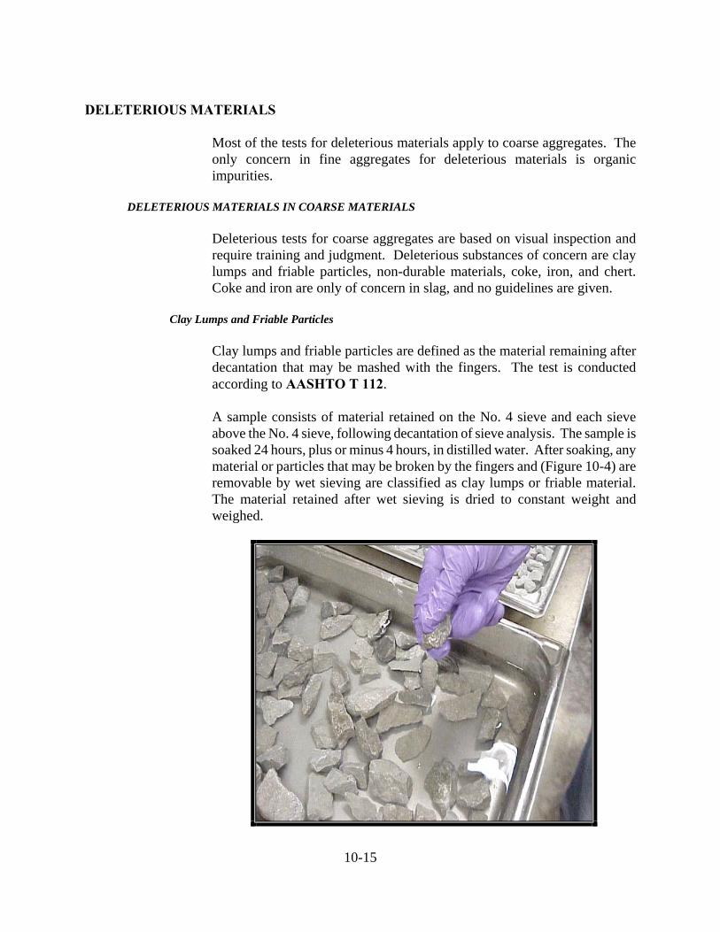
Clay Lumps and Friable Particles
Clay lumps and friable particles are defined as the material remaining after decantation that may be mashed with the fingers. The test is conducted according to AASHTO T 112.
A sample consists of material retained on the No. 4 sieve and each sieve above the No. 4 sieve, following decantation of sieve analysis. The sample is soaked 24 hours, plus or minus 4 hours, in distilled water. After soaking, any material or particles that may be broken by the fingers and (Figure 10-4) are removable by wet sieving are classified as clay lumps or friable material. The material retained after wet sieving is dried to constant weight and weighed.
10-15
Figure 10-4. Testing for Clay Lumps and Friable Particles
10-16
The percent clay or friable material is calculated by:
100 x Sample of Dry Wt.
Sieving)(Wet Retained Dry Wt. - Sample of Dry Wt. % FriableorClay
Non-Durable Materials
Non-durable materials are divided into two types:
1) Soft material as determined by ITM 206 2) Structurally weak material as determined by visual
inspection
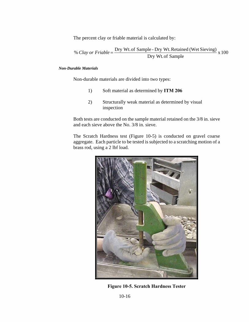
Both tests are conducted on the sample material retained on the 3/8 in. sieve and each sieve above the No. 3/8 in. sieve.
The Scratch Hardness test (Figure 10-5) is conducted on gravel coarse aggregate. Each particle to be tested is subjected to a scratching motion of a brass rod, using a 2 lbf load.
Figure 10-5. Scratch Hardness Tester
10-17
Particles are considered soft if a groove is made in the particle without deposition of metal from the brass rod or if separate particles are detached from the rock mass. A particle is classified as soft only if one-third or more of the volume is found to be soft. Structurally weak materials are visually identified and include:
1) Ocher
2) Unfossilized shells
3) Conglomerates -- cemented gravels
4) Shale -- laminated rock of clay-size minerals
5) Limonite -- iron oxide, ranging from yellow-brown to black
in color and is frequently a concretion around a soft core
6) Weathered rock that is structurally weak
7) Coal, wood, and other foreign materials
8) Materials with loosely cemented grains or a weathered coating
Particles determined to be soft or structurally weak are combined and the percent by weight of non-durable material is calculated by:
100 x Sieve in. 3/8 theabove Sample ofWeight
Sieve in. 3/8 above Material Durable-Non ofWeight Durable-Non %
Chert
Chert is a rock of varied color, composed of glassy silica, and very fine-grained quartz, and is only picked from coarse aggregate. Unweathered chert appears hard, dense, and brittle with a greasy texture. Weathered chert appears chalky and dull. Chert is likely to have concave surfaces with sharp outer edges when freshly broken.
Total chert is picked from the sample following decantation and gradation. Chert is picked from the material retained on the 3/8 in. sieve and each sieve above the 3/8 in. sieve for aggregate sizes 2 through 8, 43, 53, and 73. For aggregate sizes 9, 11, 12, and 91, chert is picked from the material retained on the No. 4 sieve and each sieve above the No. 4 sieve. The procedure for determining the total chert includes:
10-18
1) All chert, including questionable chert, is picked from the sample.
2) All pieces of questionable chert are further tested by the
following procedures:
a. Scratching glass. Chert pieces scratch glass.
b. Breaking Pieces. Chert breaks into rounded surfaces with sharp edges. If pieces do not break into rounded surfaces with sharp edges, they are added to the soft or non-durable material.
c. Reaction with acid. Chert does not react with 0.1 N
hydrochloric acid.
3) All material determined to be chert is weighed and the percent of total chert is calculated using the following formulas:
For aggregate sizes 2 through 8, 43, 53, and 73:
100 x Sieve in. 3/8 theabove Sample of Weight Total
Sieve in. 3/8 theaboveChert ofWeight Chert Total %
For aggregate sizes 9, 11, 12, and 91:
100 x Sieve 4 No. theabove Sample of Weight Total
Sieve 4 No. theaboveChert ofWeight Chert Total %
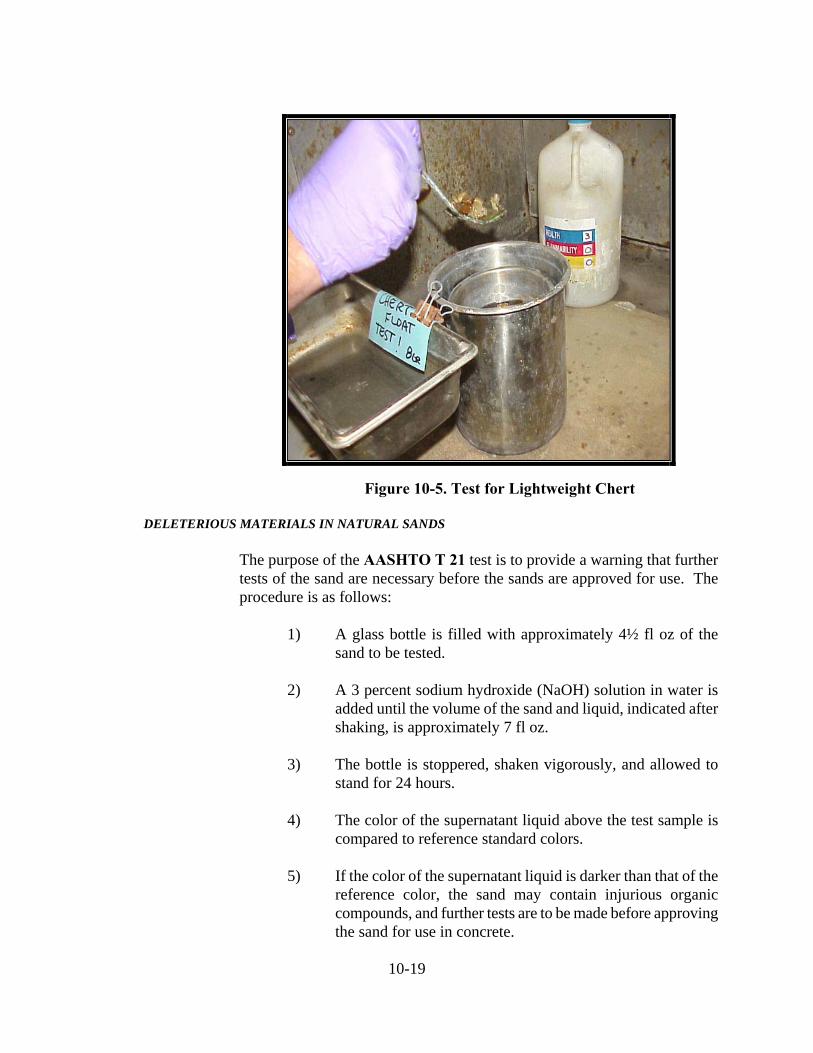
The percent chert requirement of 904.03(a) applies to chert less than 2.45 bulk specific gravity. If the percent total chert exceeds this chert requirement, the sample is tested for lightweight pieces in accordance with AASHTO T 113 to determine the percent chert less than 2.45 bulk specific gravity (Figure 10-6).
10-19
Figure 10-5. Test for Lightweight Chert
DELETERIOUS MATERIALS IN NATURAL SANDS
The purpose of the AASHTO T 21 test is to provide a warning that further tests of the sand are necessary before the sands are approved for use. The procedure is as follows:
1) A glass bottle is filled with approximately 4½ fl oz of the
sand to be tested. 2) A 3 percent sodium hydroxide (NaOH) solution in water is
added until the volume of the sand and liquid, indicated after shaking, is approximately 7 fl oz.
3) The bottle is stoppered, shaken vigorously, and allowed to
stand for 24 hours. 4) The color of the supernatant liquid above the test sample is
compared to reference standard colors. 5) If the color of the supernatant liquid is darker than that of the
reference color, the sand may contain injurious organic compounds, and further tests are to be made before approving the sand for use in concrete.
10-20
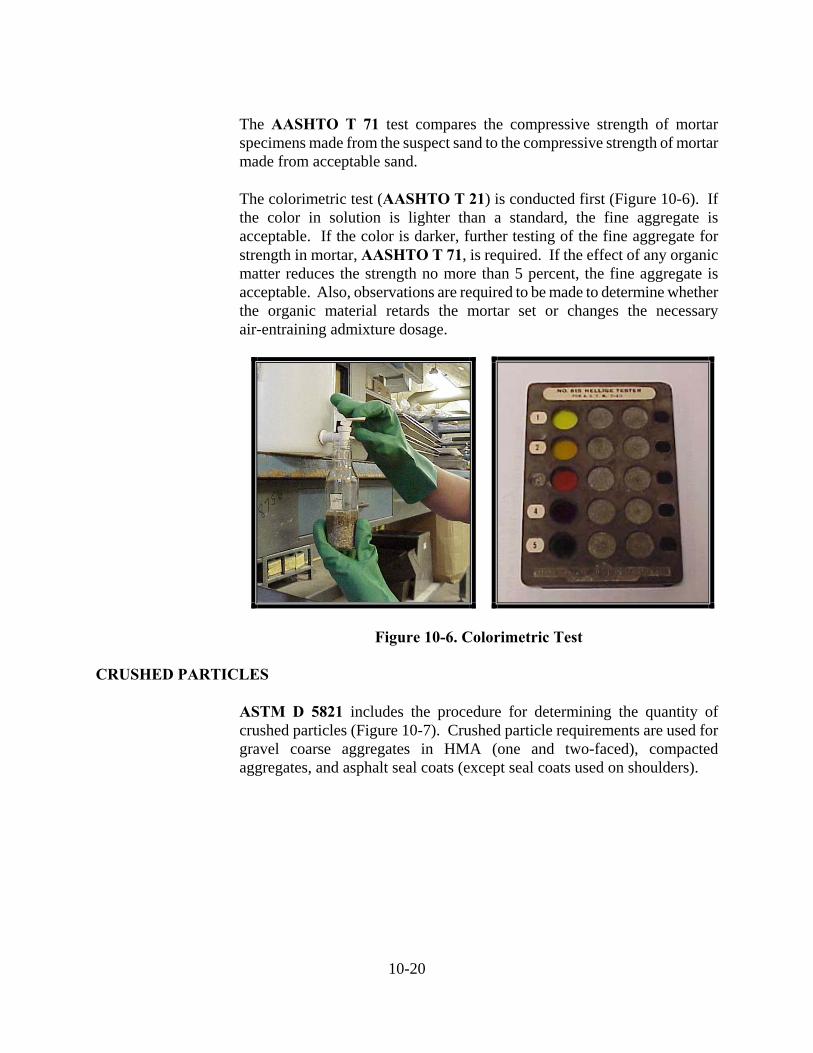
The AASHTO T 71 test compares the compressive strength of mortar specimens made from the suspect sand to the compressive strength of mortar made from acceptable sand.
The colorimetric test (AASHTO T 21) is conducted first (Figure 10-6). If the color in solution is lighter than a standard, the fine aggregate is acceptable. If the color is darker, further testing of the fine aggregate for strength in mortar, AASHTO T 71, is required. If the effect of any organic matter reduces the strength no more than 5 percent, the fine aggregate is acceptable. Also, observations are required to be made to determine whether the organic material retards the mortar set or changes the necessary air-entraining admixture dosage.
Figure 10-6. Colorimetric Test CRUSHED PARTICLES
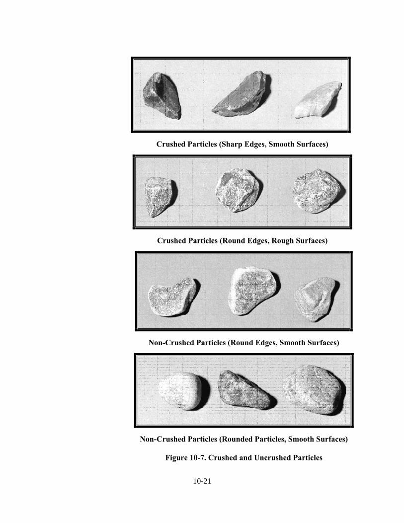
ASTM D 5821 includes the procedure for determining the quantity of crushed particles (Figure 10-7). Crushed particle requirements are used for gravel coarse aggregates in HMA (one and two-faced), compacted aggregates, and asphalt seal coats (except seal coats used on shoulders).
10-21
Crushed Particles (Sharp Edges, Smooth Surfaces)
Crushed Particles (Round Edges, Rough Surfaces)
Non-Crushed Particles (Round Edges, Smooth Surfaces)
Non-Crushed Particles (Rounded Particles, Smooth Surfaces)
Figure 10-7. Crushed and Uncrushed Particles
10-22
The test applies to all particles retained on the No. 4 sieve and is conducted as follows:
1) The total sample is washed over the No. 4 sieve and dried to a
constant weight.
2) Each particle is evaluated to verify that the crushed criteria is met. If the fractured face constitutes at least one-quarter of the maximum cross-sectional area of the rock particle and the face has sharp or slightly blunt edges, the particle is considered a crushed particle.
3) Particles are separated into two categories: (a) crushed
particles, and (b) non-crushed particles.
4) When two-faced crushed particles are required for aggregates used in HMA the procedure is repeated on the same sample.
5) The percent of crushed particles is determined by the
following formula:
100 x NF
F P
where:
P = percentage of crushed particles F = weight of crushed particles N = weight of uncrushed particles
10-23
FLAT AND ELONGATED PARTICLES
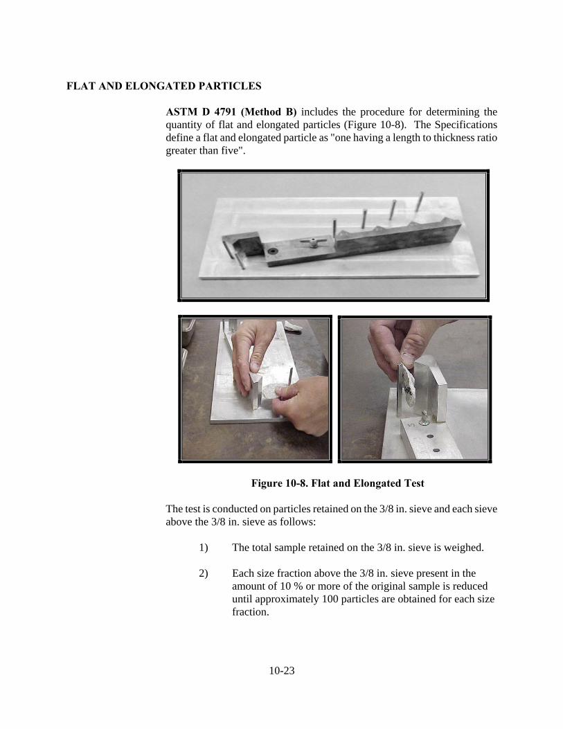
ASTM D 4791 (Method B) includes the procedure for determining the quantity of flat and elongated particles (Figure 10-8). The Specifications define a flat and elongated particle as "one having a length to thickness ratio greater than five".
Figure 10-8. Flat and Elongated Test
The test is conducted on particles retained on the 3/8 in. sieve and each sieve above the 3/8 in. sieve as follows:
1) The total sample retained on the 3/8 in. sieve is weighed.
2) Each size fraction above the 3/8 in. sieve present in the
amount of 10 % or more of the original sample is reduced until approximately 100 particles are obtained for each size fraction.
10-24
3) Each particle is measured with the proportionate caliper device set at the required ratio
4) The flat and elongated particles are weighed for each sieve.
5) The percent of the flat and elongated particles is then
determined on each sieve by the following formula:
100 x Sieveeach for Sample Reduced of Weight Total
Sieveeach for Particles E & F ofWeight Elongated andFlat %
PLASTIC LIMIT
Compacted aggregate materials, fine aggregate for SMA, mineral filler for SMA, and coarse aggregate sizes No. 43, 53, and 73, require tests for determining the plastic limit and liquid limit (Figure 10-9) of minus No. 40 sieve material. The plastic limit test may be conducted accurately only in a laboratory; however, the possibility of a plastic condition may be determined by a field check test. The liquid limit is required to be conducted in the laboratory.
Figure 10-9. Plastic Limit and Liquid Limit
The plastic limit test may not be conducted on the same sample used for any other field tests. Therefore, in addition to the sample selected for the other field tests, the Technician is required to split and dry a sample of approximately 1000 grams. The test is conducted using a small spatula, a ground-glass plate, and an evaporating dish in accordance with AASHTO T 90 as follows:
10-25
1) Using sufficient sieves, remove the material above the No. 40 sieve. All of the minus No. 40 sieve material in the sample is required. Any minus No. 40 sieve material clinging to the larger particles is required to be scraped free and all the dried composite particles retained above the No. 40 sieve is required to be broken up.
2) Thoroughly mix the minus No. 40 sieve material and select a
sample of about 20 grams.
3) Place the sample in a suitable container, preferably an evaporating dish, and thoroughly mix with distilled or de-mineralized water until the material becomes plastic enough to be easily shaped into a ball.
4) Take about half of the sample and squeeze and form the
sample into the shape of a small cigar. Place the specimen on a ground glass plate. With fingers, using just sufficient pressure, roll the specimen into a thread of uniform diameter throughout the sample length. The rate of rolling will be between 80 and 90 strokes per minute, counting a stroke as a complete motion of the hand forward and back to the starting position. The rolling continues until the thread is 1/8 in. in diameter.
Most compacted aggregate materials do not contain plastic fines. If the specimen cannot be rolled into a thread of 1/8 in. diameter, the Technician may assume that the material is either nonplastic or has a low plastic content, and no additional testing is required. If the specimen may be rolled into a thread of 1/8 in., the material is considered plastic and a sample is required to be sent to the District laboratory for an accurate determination of plasticity index.
TOTAL MOISTURE CONTENT
When aggregates are used in portland cement concrete mixtures, the moisture of the aggregates is required to be determined to adjust aggregate weights for moisture content and to determine the moisture contribution to the mixing water.
10-26
When a moisture content is desired, the sample is required to be reduced to test size and the test is conducted as quickly as possible after the sample has been obtained. Any delay in conducting the test after the sample has been selected may allow the material to lose moisture and result in inaccurate results.
The test is conducted in accordance with AASHTO T 255 as follows:
1) Weigh the sample before drying and record the weight.
2) Dry the sample and cool to room temperature.
3) Weigh the sample and record the weight.
4) Determine the moisture percent using this formula:
100 x DryWeight
Dry Weight - Weight Wet Moisture %