10” Table Saw - SIP Industrial Products Ltd · 10” Table Saw Please read and fully understand...
14
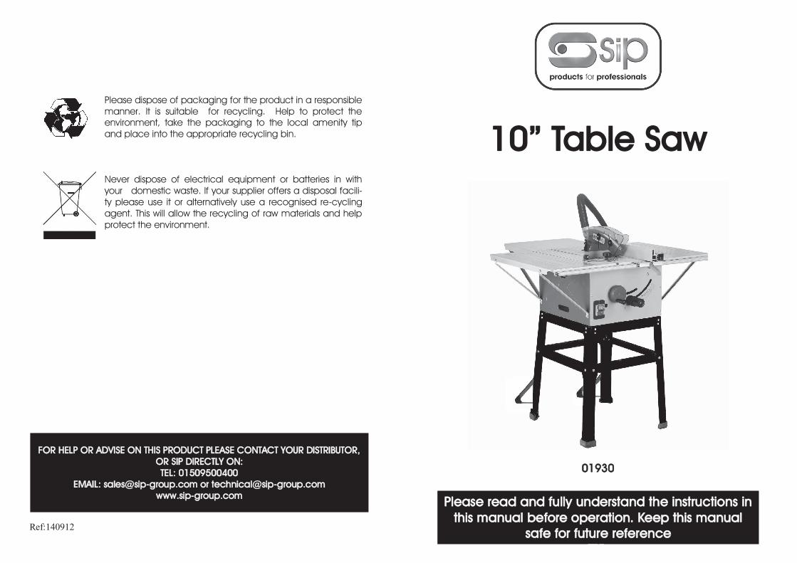
Please dispose of packaging for the product in a responsible manner. It is suitable for recycling. Help to protect the environment, take the packaging to the local amenity tip and place into the appropriate recycling bin. Never dispose of electrical equipment or batteries in with your domestic waste. If your supplier offers a disposal facili- ty please use it or alternatively use a recognised re-cycling agent. This will allow the recycling of raw materials and help protect the environment. Ref:140912 FOR HELP OR ADVISE ON THIS PRODUCT PLEASE CONTACT YOUR DISTRIBUTOR, OR SIP DIRECTLY ON: TEL: 01509500400 EMAIL: [email protected] or [email protected] www.sip-group.com 1 10” Table Saw Please read and fully understand the instructions in this manual before operation. Keep this manual safe for future reference 01930
-
Upload
nguyentuong -
Category
Documents
-
view
235 -
download
3
Transcript of 10” Table Saw - SIP Industrial Products Ltd · 10” Table Saw Please read and fully understand...
28
Please dispose of packaging for the product in a responsible
manner. It is suitable for recycling. Help to protect the
environment, take the packaging to the local amenity tip
and place into the appropriate recycling bin.
Never dispose of electrical equipment or batteries in with
your domestic waste. If your supplier offers a disposal facili-
ty please use it or alternatively use a recognised re-cycling
agent. This will allow the recycling of raw materials and help
protect the environment.
Ref:140912
FOR HELP OR ADVISE ON THIS PRODUCT PLEASE CONTACT YOUR DISTRIBUTOR,
OR SIP DIRECTLY ON:
TEL: 01509500400
EMAIL: [email protected] or [email protected]
www.sip-group.com
1
10” Table Saw
Please read and fully understand the instructions in
this manual before operation. Keep this manual
safe for future reference
01930

2 27
Declaration of Conformity
We
SIP (Industrial Products) Ltd Gelders Hall Road
Shepshed
Loughborough
Leicestershire
LE12 9NH
England
As the manufacturer's authorised representative within the EC
declare that the
10” Table Saw - SIP Part. No. 01930 Manufacturers Part No. M1YD-JF1C-250
Conforms to the requirements of the following directive(s), as indicated.
2006/42/EC Machinery Directive
2006/95/EC Low Voltage Directive
2004/108/EC EMC Directive
2002/95/EC ROHS Directive
And the following harmonised standard(s)
EN 55014-1/A1:2009
EN 55014-2/A2:2008 EN 61000-3-2/A2:2009
EN 61000-3-11:2000
EN 61029-1:2009
EN 61029-2-1:2010
Signed:
Mr P. Ippaso - Director - SIP (Industrial Products) Ltd
Date: 05/07/2011.
DECLARATION OF CONFORMITY
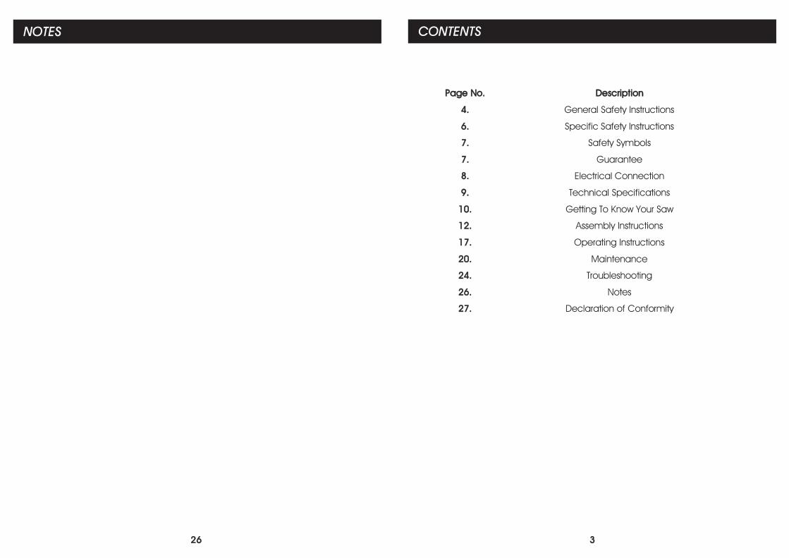
26
NOTES
3
Page No. Description
4. General Safety Instructions
6. Specific Safety Instructions
7. Safety Symbols
7. Guarantee
8. Electrical Connection
9. Technical Specifications
10. Getting To Know Your Saw
12. Assembly Instructions
17. Operating Instructions
20. Maintenance
24. Troubleshooting
26. Notes
27. Declaration of Conformity
CONTENTS
4
GENERAL SAFETY INSTRUCTIONS
Please read the following instructions carefully, failure to do so could lead to serious
personal injury.
When using electric tools, basic safety precautions should always be followed to re-
duce the risk of fire, electric shock and personal injury.
Read all these instructions before operating the tool and save this user manual for fu-
ture reference.
SIP recommends that this tool should not be modified or used for any application oth-
er than that for which it was designed. If you are unsure of its relative applications do
not hesitate to contact us and we will be more than happy to advise you.
KNOW YOUR POWER TOOL: Read and understand the owner's manual and labels af-
fixed to the tool. Learn its applications and limitations, as well as the potential hazards
specific to this tool.
KEEP WORK AREA CLEAN AND WELL LIT: Cluttered work benches and dark areas invite
accidents. Floors must not be slippery due to oil, water or sawdust etc.
DO NOT USE THE TOOL IN DANGEROUS ENVIRONMENTS: Do not use power tools in
damp or wet locations, or expose them to rain. Provide adequate space surrounding
the work area. Do not use in environments with a potentially explosive atmosphere.
KEEP CHILDREN AND UNTRAINED PERSONNEL AWAY FROM THE WORK AREA: All visitors
should be kept at a safe distance from the work area.
STORE TOOLS SAFELY WHEN THEY ARE NOT IN USE: All tools should be stored in a dry,
locked cupboard wherever possible and out of the reach of children.
WEAR THE CORRECT CLOTHING: Do not wear loose clothing, neckties, rings, bracelets,
or other jewellery, which may get caught in moving parts. Non-slip footwear is recom-
mended. Wear protective hair covering to contain long hair. Roll long sleeves up
above the elbow.
USE SAFETY GOGGLES AND EAR PROTECTION: Wear CE approved safety goggles at all
times, Normal spectacles only have impact resistant lenses, they are NOT safety glass-
es. A face or dust mask should be worn if the operation is dusty and ear protectors
(plugs or muffs) should be worn, particularly during extended periods of operation.
PROTECT YOURSELF FROM ELECTRIC SHOCK: When working with power tools, avoid
contact with any earthed items (e.g. pipes, radiators, hobs and refrigerators, etc.). It is
advisable wherever possible to use an RCD (residual current device) at the mains
socket.
STAY ALERT: Always watch what you are doing and use common sense. Do not oper-
ate a power tool when you are tired or under the influence of alcohol or drugs.
DISCONNECT THE TOOL FROM THE MAINS SUPPLY: When not in use, before servicing
and when changing accessories such as cutters, blades etc.
AVOID UNINTENTIONAL STARTING: Make sure the switch is in the OFF position before
connecting the tool to the mains supply.
NEVER LEAVE THE TOOL RUNNING / CONNECTED WHILST UNATTENDED: Turn off the tool
and disconnect it from the mains supply between jobs. Do not leave machine until it
25
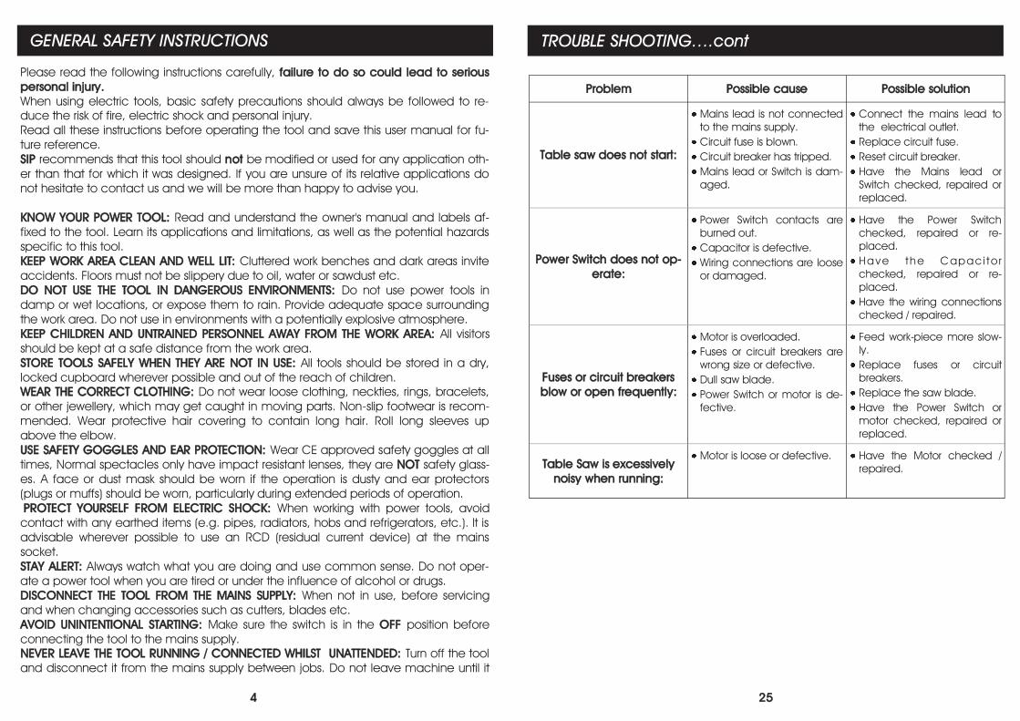
Problem Possible cause Possible solution
Table saw does not start:
Mains lead is not connected
to the mains supply.
Circuit fuse is blown.
Circuit breaker has tripped.
Mains lead or Switch is dam-
aged.
Connect the mains lead to
the electrical outlet.
Replace circuit fuse.
Reset circuit breaker.
Have the Mains lead or
Switch checked, repaired or
replaced.
Power Switch does not op-
erate:
Power Switch contacts are
burned out.
Capacitor is defective.
Wiring connections are loose
or damaged.
Have the Power Switch
checked, repaired or re-
placed.
Have the C apaci tor
checked, repaired or re-
placed.
Have the wiring connections
checked / repaired.
Fuses or circuit breakers
blow or open frequently:
Motor is overloaded.
Fuses or circuit breakers are
wrong size or defective.
Dull saw blade.
Power Switch or motor is de-
fective.
Feed work-piece more slow-
ly.
Replace fuses or circuit
breakers.
Replace the saw blade.
Have the Power Switch or
motor checked, repaired or
replaced.
Table Saw is excessively
noisy when running:
Motor is loose or defective. Have the Motor checked /
repaired.
TROUBLE SHOOTING….cont
24
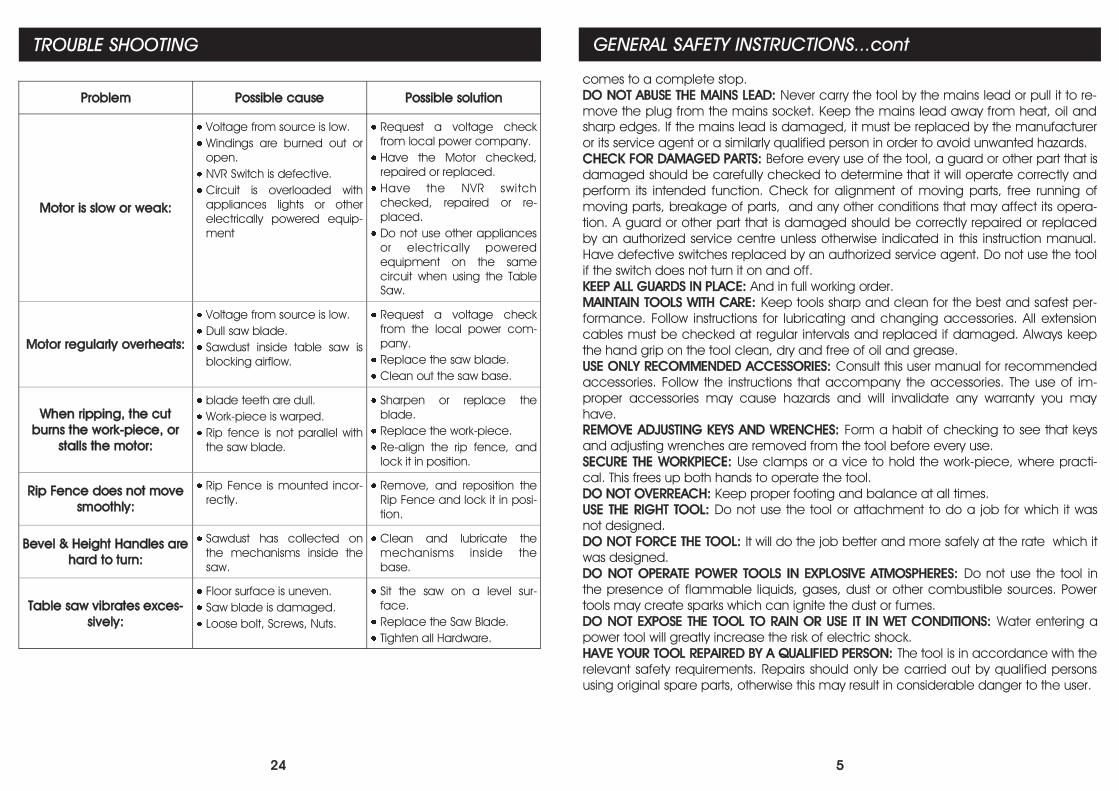
Problem Possible cause Possible solution
Motor is slow or weak:
Voltage from source is low.
Windings are burned out or
open.
NVR Switch is defective.
Circuit is overloaded with
appliances lights or other
electrically powered equip-
ment
Request a voltage check
from local power company.
Have the Motor checked,
repaired or replaced.
Have the NVR switch
checked, repaired or re-
placed.
Do not use other appliances
or electrically powered
equipment on the same
circuit when using the Table
Saw.
Motor regularly overheats:
Voltage from source is low.
Dull saw blade.
Sawdust inside table saw is
blocking airflow.
Request a voltage check
from the local power com-
pany.
Replace the saw blade.
Clean out the saw base.
When ripping, the cut
burns the work-piece, or
stalls the motor:
blade teeth are dull.
Work-piece is warped.
Rip fence is not parallel with
the saw blade.
Sharpen or replace the
blade.
Replace the work-piece.
Re-align the rip fence, and
lock it in position.
Rip Fence does not move
smoothly:
Rip Fence is mounted incor-
rectly.
Remove, and reposition the
Rip Fence and lock it in posi-
tion.
Bevel & Height Handles are
hard to turn:
Sawdust has collected on
the mechanisms inside the
saw.
Clean and lubricate the
mechanisms inside the
base.
Table saw vibrates exces-
sively:
Floor surface is uneven.
Saw blade is damaged.
Loose bolt, Screws, Nuts.
Sit the saw on a level sur-
face.
Replace the Saw Blade.
Tighten all Hardware.
TROUBLE SHOOTING
5
GENERAL SAFETY INSTRUCTIONS...cont
comes to a complete stop.
DO NOT ABUSE THE MAINS LEAD: Never carry the tool by the mains lead or pull it to re-
move the plug from the mains socket. Keep the mains lead away from heat, oil and
sharp edges. If the mains lead is damaged, it must be replaced by the manufacturer
or its service agent or a similarly qualified person in order to avoid unwanted hazards.
CHECK FOR DAMAGED PARTS: Before every use of the tool, a guard or other part that is
damaged should be carefully checked to determine that it will operate correctly and
perform its intended function. Check for alignment of moving parts, free running of
moving parts, breakage of parts, and any other conditions that may affect its opera-
tion. A guard or other part that is damaged should be correctly repaired or replaced
by an authorized service centre unless otherwise indicated in this instruction manual.
Have defective switches replaced by an authorized service agent. Do not use the tool
if the switch does not turn it on and off.
KEEP ALL GUARDS IN PLACE: And in full working order.
MAINTAIN TOOLS WITH CARE: Keep tools sharp and clean for the best and safest per-
formance. Follow instructions for lubricating and changing accessories. All extension
cables must be checked at regular intervals and replaced if damaged. Always keep
the hand grip on the tool clean, dry and free of oil and grease.
USE ONLY RECOMMENDED ACCESSORIES: Consult this user manual for recommended
accessories. Follow the instructions that accompany the accessories. The use of im-
proper accessories may cause hazards and will invalidate any warranty you may
have.
REMOVE ADJUSTING KEYS AND WRENCHES: Form a habit of checking to see that keys
and adjusting wrenches are removed from the tool before every use.
SECURE THE WORKPIECE: Use clamps or a vice to hold the work-piece, where practi-
cal. This frees up both hands to operate the tool.
DO NOT OVERREACH: Keep proper footing and balance at all times.
USE THE RIGHT TOOL: Do not use the tool or attachment to do a job for which it was
not designed.
DO NOT FORCE THE TOOL: It will do the job better and more safely at the rate which it
was designed.
DO NOT OPERATE POWER TOOLS IN EXPLOSIVE ATMOSPHERES: Do not use the tool in
the presence of flammable liquids, gases, dust or other combustible sources. Power
tools may create sparks which can ignite the dust or fumes.
DO NOT EXPOSE THE TOOL TO RAIN OR USE IT IN WET CONDITIONS: Water entering a
power tool will greatly increase the risk of electric shock.
HAVE YOUR TOOL REPAIRED BY A QUALIFIED PERSON: The tool is in accordance with the
relevant safety requirements. Repairs should only be carried out by qualified persons
using original spare parts, otherwise this may result in considerable danger to the user.
6
1. Use only the blade flange specified for this tool.
2. Be careful not to damage the arbor, flange (especially the installing surface) or
NUT. Damage to these parts could result in blade breakage. And / or operator injury.
3. Make sure that the table base is properly secured so it will not move during oper-
ation.
4. For your safety; remove the chippings and work debris etc. from the table top and
from inside the extraction port before each operation.
5. Avoid cutting nails / screws etc.; Remove all obstructions from the work-piece be-
fore cutting.
6. Make sure that all keys and wrenches are removed before switching on the saw.
7. Be sure that the blade does not come into contact with the table and / or table
insert when the blade is in operation.
8. Always use the supplied push stick whenever possible.
9. Keep hands out of path of saw blade, never reach around saw blade.
10. Make sure the blade is clear of the work-piece before the switch is turned on.
11. Before making the first cut using the saw, turn the blade by hand to ensure noth-
ing is catching, then turn the saw on and let it run for a while; Watch for vibration or
wobbling that could indicate poor installation or a poorly balanced blade. Adjust or
replace as necessary.
12. Allow the blade to run up to full speed before cutting.
13. Stop operation immediately if you notice anything abnormal.
14. Wait for the saw blade to stop completely and remove from mains supply before
servicing or adjusting tool.
15. Be alert at all times, especially during repetitive, monotonous operations. Don't
be lulled into a false sense of security. Blades are extremely unforgiving.
16. Use of improper accessories such as abrasive wheels may cause damage to
the saw and surrounding area as well as increasing the risk of injury.
17. Turn off the saw and wait for it to complete stop before moving work-piece or
changing settings.
18. Do not modify the saw to do tasks other than those intended.
19. Be sure to use a push stick (21) when making longitudinal cuts in work-pieces
smaller than 120 mm in width and wherever possible. A push stick is supplied with the
saw!
CAUTION: The warnings and cautions mentioned in this user manual
can not cover all possible conditions and situations that may occur. It
must be understood by the operator that common sense and caution
are factors which cannot be built into this product, but must be ap-
plied.
SPECIFIC SAFETY INSTRUCTIONS
23
MAINTENANCE….cont
Fig. 30
22
MAINTENANCE….cont
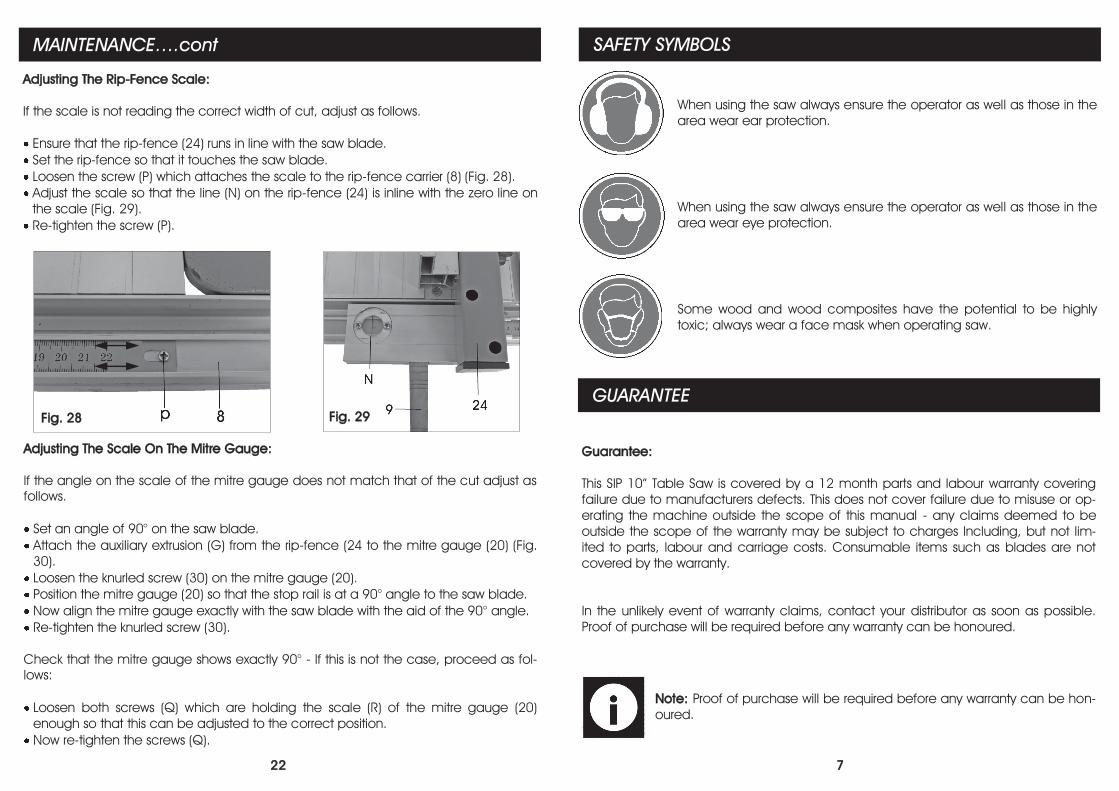
Adjusting The Rip-Fence Scale:
If the scale is not reading the correct width of cut, adjust as follows.
Ensure that the rip-fence (24) runs in line with the saw blade.
Set the rip-fence so that it touches the saw blade.
Loosen the screw (P) which attaches the scale to the rip-fence carrier (8) (Fig. 28).
Adjust the scale so that the line (N) on the rip-fence (24) is inline with the zero line on
the scale (Fig. 29).
Re-tighten the screw (P).
Fig. 29 Fig. 28
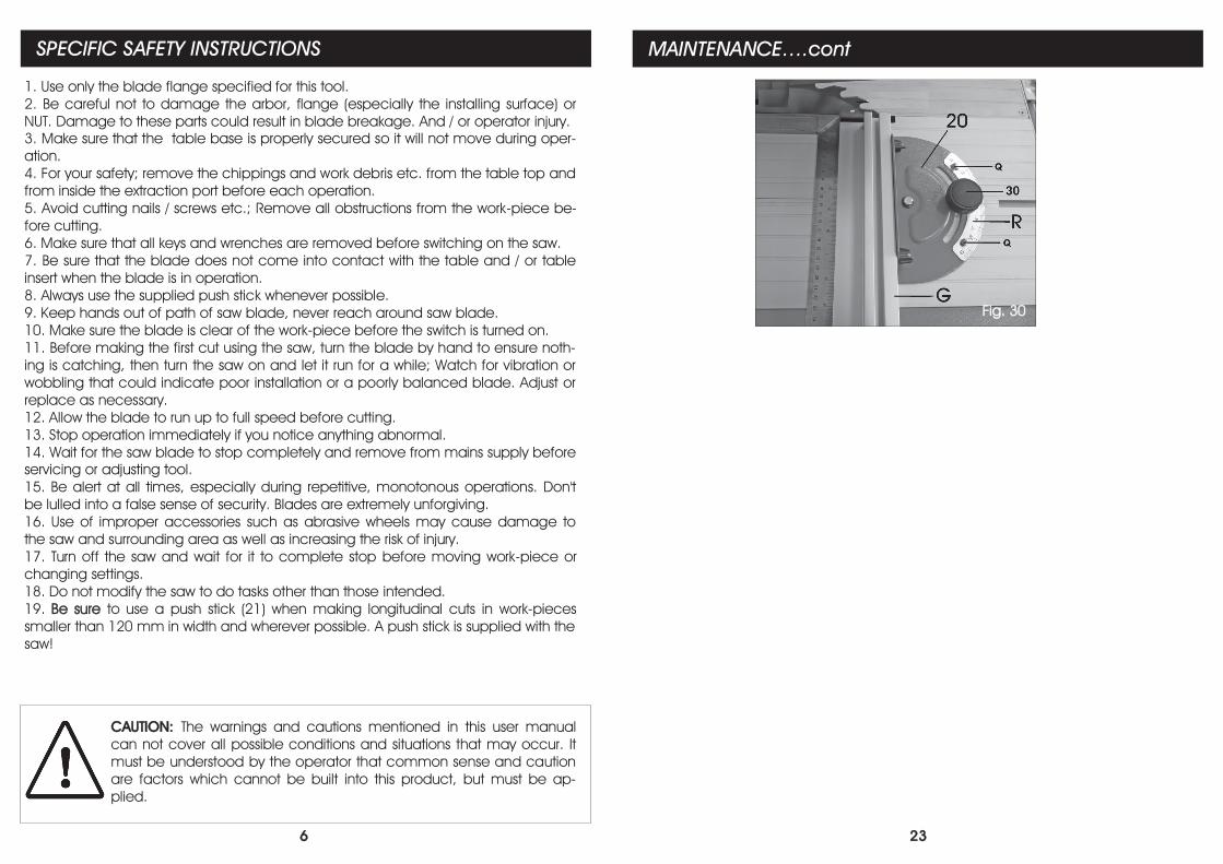
Adjusting The Scale On The Mitre Gauge:
If the angle on the scale of the mitre gauge does not match that of the cut adjust as
follows.
Set an angle of 90° on the saw blade.
Attach the auxiliary extrusion (G) from the rip-fence (24 to the mitre gauge (20) (Fig.
30).
Loosen the knurled screw (30) on the mitre gauge (20).
Position the mitre gauge (20) so that the stop rail is at a 90° angle to the saw blade.
Now align the mitre gauge exactly with the saw blade with the aid of the 90° angle.
Re-tighten the knurled screw (30).
Check that the mitre gauge shows exactly 90° - If this is not the case, proceed as fol-
lows:
Loosen both screws (Q) which are holding the scale (R) of the mitre gauge (20)
enough so that this can be adjusted to the correct position.
Now re-tighten the screws (Q).
7
SAFETY SYMBOLS
When using the saw always ensure the operator as well as those in the
area wear ear protection.
When using the saw always ensure the operator as well as those in the
area wear eye protection.
Some wood and wood composites have the potential to be highly
toxic; always wear a face mask when operating saw.
GUARANTEE
Guarantee:
This SIP 10” Table Saw is covered by a 12 month parts and labour warranty covering
failure due to manufacturers defects. This does not cover failure due to misuse or op-
erating the machine outside the scope of this manual - any claims deemed to be
outside the scope of the warranty may be subject to charges Including, but not lim-
ited to parts, labour and carriage costs. Consumable items such as blades are not
covered by the warranty.
In the unlikely event of warranty claims, contact your distributor as soon as possible.
Proof of purchase will be required before any warranty can be honoured.
Note: Proof of purchase will be required before any warranty can be hon-
oured.
8
ELECTRICAL CONNECTION
Note: Always make sure the mains supply is of the correct voltage and the
correct fuse protection is used. In the event of replacing the fuse always
replace the fuse with the same value as the original.
Note: If an extension lead is required in order to reach the mains supply;
ensure that this too is rated for the correct voltage and fuse rating.
Note: The cross section of the extension lead should be checked so that it
is of sufficient size so as to reduce the chances of voltage drops.
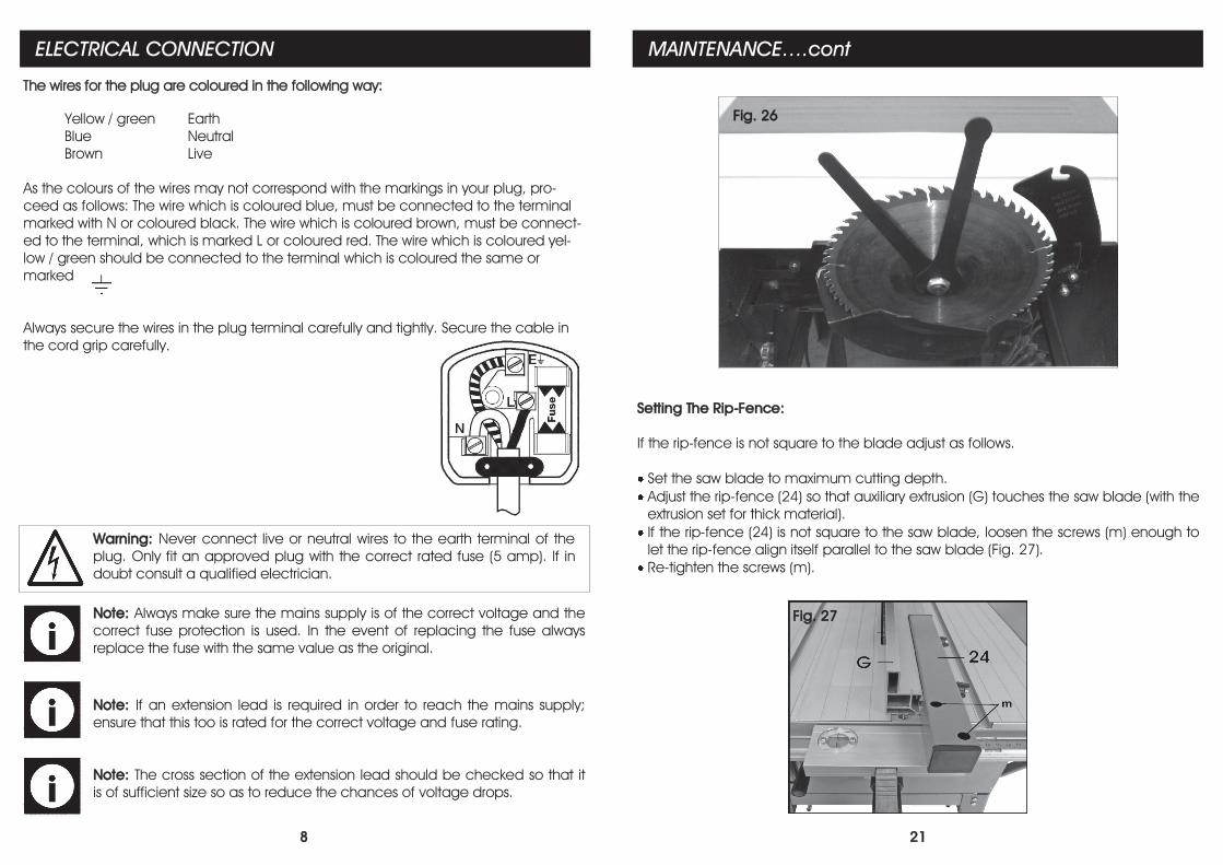
Warning: Never connect live or neutral wires to the earth terminal of the
plug. Only fit an approved plug with the correct rated fuse (5 amp). If in
doubt consult a qualified electrician.
Yellow / green Earth
Blue Neutral
Brown Live
As the colours of the wires may not correspond with the markings in your plug, pro-
ceed as follows: The wire which is coloured blue, must be connected to the terminal
marked with N or coloured black. The wire which is coloured brown, must be connect-
ed to the terminal, which is marked L or coloured red. The wire which is coloured yel-
low / green should be connected to the terminal which is coloured the same or
marked
Always secure the wires in the plug terminal carefully and tightly. Secure the cable in
the cord grip carefully.
The wires for the plug are coloured in the following way:
21
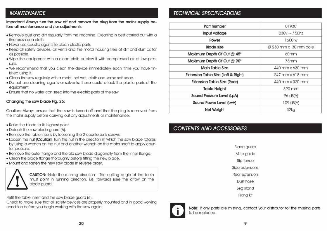
Setting The Rip-Fence:
If the rip-fence is not square to the blade adjust as follows.
Set the saw blade to maximum cutting depth.
Adjust the rip-fence (24) so that auxiliary extrusion (G) touches the saw blade (with the
extrusion set for thick material).
If the rip-fence (24) is not square to the saw blade, loosen the screws (m) enough to
let the rip-fence align itself parallel to the saw blade (Fig. 27).
Re-tighten the screws (m).
Fig. 27
MAINTENANCE….cont
Fig. 26
20
MAINTENANCE
Important! Always turn the saw off and remove the plug from the mains supply be-
fore all maintenance and / or adjustments.
Remove dust and dirt regularly from the machine. Cleaning is best carried out with a
fine brush or a cloth.
Never use caustic agents to clean plastic parts.
Keep all safety devices, air vents and the motor housing free of dirt and dust as far
as possible.
Wipe the equipment with a clean cloth or blow it with compressed air at low pres-
sure.
We recommend that you clean the device immediately each time you have fin-
ished using it.
Clean the saw regularly with a moist, not wet, cloth and some soft soap.
Do not use cleaning agents or solvents; these could attack the plastic parts of the
equipment.
Ensure that no water can seep into the electric parts of the saw.
Changing the saw blade Fig. 26:
Caution: Always ensure that the saw is turned off and that the plug is removed from
the mains supply before carrying out any adjustments or maintenance.
Raise the blade to its highest point.
Detach the saw blade guard (6).
Remove the table inserts by loosening the 2 countersunk screws.
Loosen the nut (Caution! Turn the nut in the direction in which the saw blade rotates)
by using a wrench on the nut and another wrench on the motor shaft to apply coun-
ter-pressure.
Remove the outer flange and the old saw blade diagonally from the inner flange.
Clean the blade flange thoroughly before fitting the new blade.
Mount and fasten the new saw blade in reverse order.
CAUTION: Note the running direction - The cutting angle of the teeth
must point in running direction, i.e. forwards (see the arrow on the
blade guard).
Refit the table insert and the saw blade guard (6).
Check to make sure that all safety devices are properly mounted and in good working
condition before you begin working with the saw again.
9
TECHNICAL SPECIFICATIONS
Part number 01930
Input voltage 230v ~ / 50hz
Power 1600 w
Blade size Ø 250 mm x 30 mm bore
Maximum Depth Of Cut @ 45° 60mm
Maximum Depth Of Cut @ 90° 73mm
Main Table Size 440 mm x 630 mm
Extension Table Size (Left & Right) 247 mm x 618 mm
Extension Table Size (Rear) 440 mm x 320 mm
Table Height 890 mm
Sound Pressure Level (LpA) 96 dB(A)
Sound Power Level (LwA) 109 dB(A)
Net Weight 32kg
CONTENTS AND ACCESSORIES
Blade guard
Mitre guide
Rip fence
Side extensions
Rear extension
Dust hose
Leg stand
Fixing kit
Note: If any parts are missing, contact your distributor for the missing parts
to be replaced.
10
GETTING TO KNOW YOUR SAW
1 2 3 4 5 6 7
8
9
10
11
12
13 14
15
16
17
18
19
20
24
25
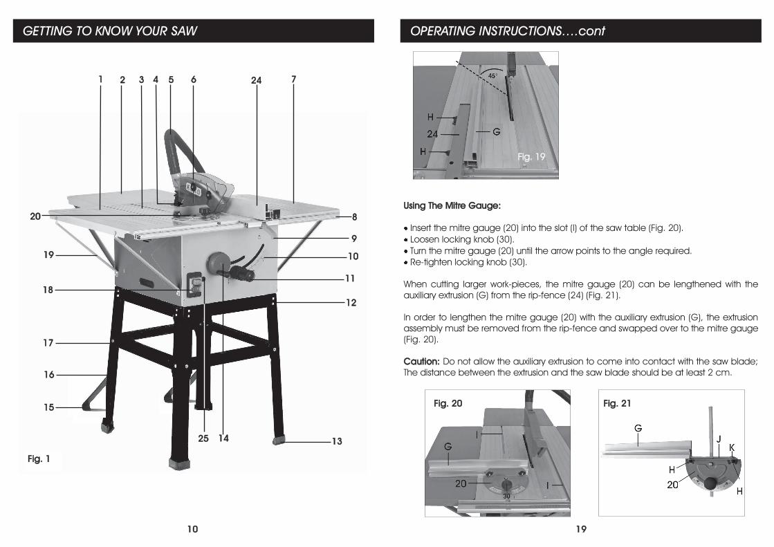
Fig. 1
19
OPERATING INSTRUCTIONS….cont
Fig. 19
Using The Mitre Gauge:
Insert the mitre gauge (20) into the slot (I) of the saw table (Fig. 20).
Loosen locking knob (30).
Turn the mitre gauge (20) until the arrow points to the angle required.
Re-tighten locking knob (30).
When cutting larger work-pieces, the mitre gauge (20) can be lengthened with the
auxiliary extrusion (G) from the rip-fence (24) (Fig. 21).
In order to lengthen the mitre gauge (20) with the auxiliary extrusion (G), the extrusion
assembly must be removed from the rip-fence and swapped over to the mitre gauge
(Fig. 20).
Caution: Do not allow the auxiliary extrusion to come into contact with the saw blade;
The distance between the extrusion and the saw blade should be at least 2 cm.
Fig. 20 Fig. 21
18
OPERATING INSTRUCTIONS….cont
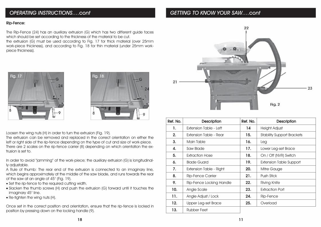
Loosen the wing nuts (H) in order to turn the extrusion (Fig. 19).
The extrusion can be removed and replaced in the correct orientation on either the
left or right side of the rip-fence depending on the type of cut and size of work-piece.
There are 2 scales on the rip-fence carrier (8) depending on which orientation the ex-
trusion is set to.
In order to avoid “jamming” of the work-piece; the auxiliary extrusion (G) is longitudinal-
ly adjustable.
A Rule of thumb: The rear end of the extrusion is connected to an imaginary line,
which begins approximately at the middle of the saw blade, and runs towards the rear
of the saw at an angle of 45° (Fig. 19).
Set the rip-fence to the required cutting width.
Slacken the thumb screws (H) and push the extrusion (G) forward until it touches the
imaginary 45° line.
Re-tighten the wing nuts (H).
Once set in the correct position and orientation, ensure that the rip-fence is locked in
position by pressing down on the locking handle (9).
Fig. 17 Fig. 18
Rip-Fence:
The Rip-Fence (24) has an auxiliary extrusion (G) which has two different guide faces
which should be set according to the thickness of the material to be cut.
the extrusion (G) must be used according to Fig. 17 for thick material (over 25mm
work-piece thickness), and according to Fig. 18 for thin material (under 25mm work-
piece thickness).
11
GETTING TO KNOW YOUR SAW….cont
Ref. No. Description Ref. No. Description
1. Extension Table - Left 14 Height Adjust
2. Extension Table - Rear 15. Stability Support Brackets
3. Main Table 16. Leg
4. Saw Blade 17. Lower Leg-set Brace
5. Extraction Hose 18. On / Off (NVR) Switch
6. Blade Guard 19. Extension Table Support
7. Extension Table - Right 20. Mitre Gauge
8. Rip-Fence Carrier 21. Push Stick
9. Rip-Fence Locking Handle 22. Riving Knife
10. Angle Scale 23. Extraction Port
11. Angle Adjust / Lock 24. Rip-Fence
12. Upper Leg-set Brace 25. Overload
13. Rubber Feet
12
Unpack the table saw and check it for damage which may have occurred in transit.
The saw should be set up where it can stand firmly on a flat level surface.
All covers and safety devices have to be correctly fitted and in full working order be-
fore the machine is switched on.
The saw blade should run freely.
When working with wood that has been processed before, watch out for foreign
bodies such as nails or screws etc. Always check and remove prior to running the
work-piece through the saw.
Before you actuate the On/Off switch, make sure that the saw blade is correctly and
securely fitted and that the machines moving parts run smoothly.
Before you connect the machine to the power supply, make sure the data on the
rating plate is the same as that for your mains supply.
Fitting the leg-set to the main saw:
Place the main saw assembly, table face down, onto a flat level surface.
Place the saw onto cardboard, or similar, to reduce the risk of damage and
ensure that the blade is in its lowest position.
ASSEMBLY INSTRUCTIONS
WARNING! Always ensure that the saw is turned off and that the plug is disconnected
from the mains supply before carrying out any adjustments, repairs or maintenance.
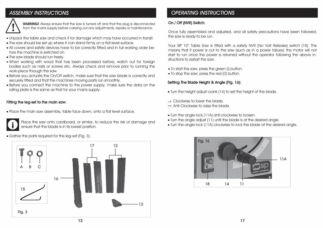
Gather the parts required for the leg-set (Fig. 3).
Fig. 3
A C B
15
16
12 17
13
17
OPERATING INSTRUCTIONS
On / Off (NVR) Switch:
Once fully assembled and adjusted, and all safety precautions have been followed;
the saw is ready to be run.
Your SIP 10” Table Saw is fitted with a safety NVR (No Volt Release) switch (18). This
means that if power is cut to the saw (such as in a power failure); the motor will not
start to run once the power is returned without the operator following the above in-
structions to restart the saw.
To start the saw; press the green (I) button.
To stop the saw; press the red (0) button.
Setting The Blade Height & Angle (Fig. 16):
Turn the height adjust crank (14) to set the height of the blade.
Clockwise to lower the blade.
Anti-Clockwise to raise the blade.
Turn the angle lock (11A) anti-clockwise to loosen.
Turn the angle adjust (11) until the blade is at the desired angle.
Turn the angle lock (11A) clockwise to lock the blade at the desired angle.
Fig. 16
18 14 11
11A
16
ASSEMBLY INSTRUCTIONS….cont
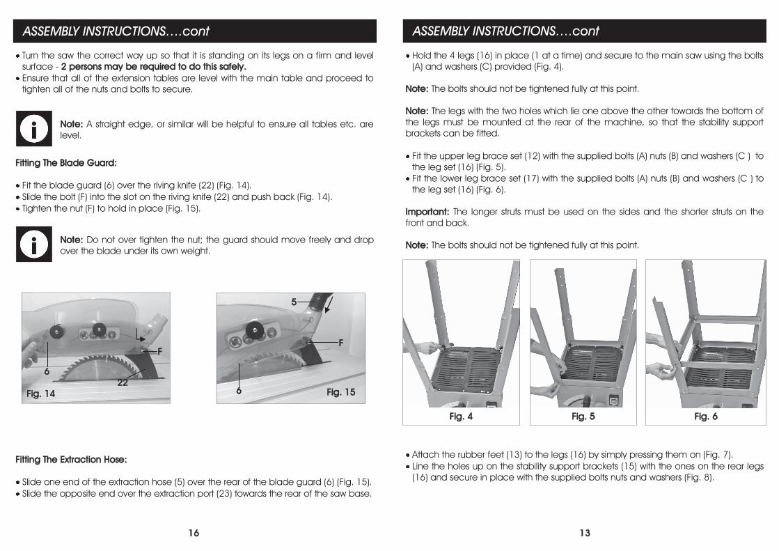
Fitting The Blade Guard:
Fit the blade guard (6) over the riving knife (22) (Fig. 14).
Slide the bolt (F) into the slot on the riving knife (22) and push back (Fig. 14).
Tighten the nut (F) to hold in place (Fig. 15).
Turn the saw the correct way up so that it is standing on its legs on a firm and level
surface - 2 persons may be required to do this safely.
Ensure that all of the extension tables are level with the main table and proceed to
tighten all of the nuts and bolts to secure.
Note: A straight edge, or similar will be helpful to ensure all tables etc. are
level.
Note: Do not over tighten the nut; the guard should move freely and drop
over the blade under its own weight.
Fitting The Extraction Hose:
Slide one end of the extraction hose (5) over the rear of the blade guard (6) (Fig. 15).
Slide the opposite end over the extraction port (23) towards the rear of the saw base.
6
F
5
Fig. 15
6
22
F
Fig. 14
13
ASSEMBLY INSTRUCTIONS….cont
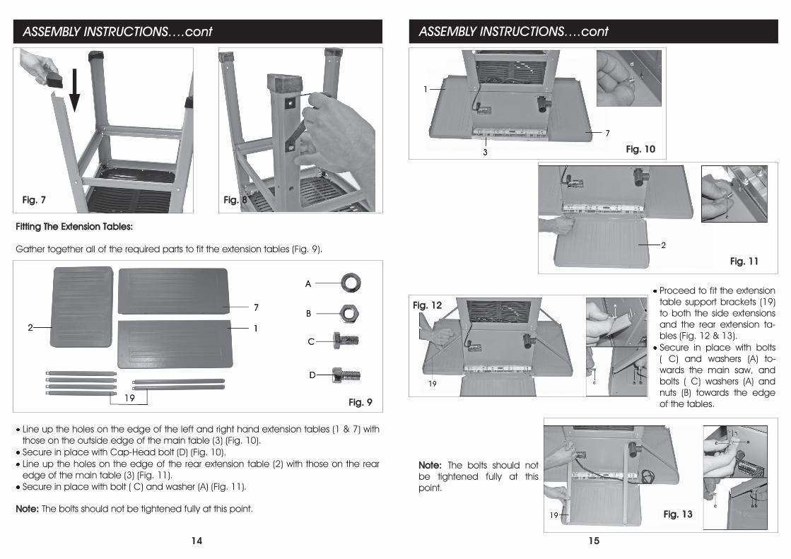
Attach the rubber feet (13) to the legs (16) by simply pressing them on (Fig. 7).
Line the holes up on the stability support brackets (15) with the ones on the rear legs
(16) and secure in place with the supplied bolts nuts and washers (Fig. 8).
Hold the 4 legs (16) in place (1 at a time) and secure to the main saw using the bolts
(A) and washers (C) provided (Fig. 4).
Note: The bolts should not be tightened fully at this point.
Note: The legs with the two holes which lie one above the other towards the bottom of
the legs must be mounted at the rear of the machine, so that the stability support
brackets can be fitted.
Fit the upper leg brace set (12) with the supplied bolts (A) nuts (B) and washers (C ) to
the leg set (16) (Fig. 5).
Fit the lower leg brace set (17) with the supplied bolts (A) nuts (B) and washers (C ) to
the leg set (16) (Fig. 6).
Important: The longer struts must be used on the sides and the shorter struts on the
front and back.
Note: The bolts should not be tightened fully at this point.
Fig. 6 Fig. 5 Fig. 4
14
ASSEMBLY INSTRUCTIONS….cont
Fig. 7 Fig. 8
Fitting The Extension Tables:
Gather together all of the required parts to fit the extension tables (Fig. 9).
Line up the holes on the edge of the left and right hand extension tables (1 & 7) with
those on the outside edge of the main table (3) (Fig. 10).
Secure in place with Cap-Head bolt (D) (Fig. 10).
Line up the holes on the edge of the rear extension table (2) with those on the rear
edge of the main table (3) (Fig. 11).
Secure in place with bolt ( C) and washer (A) (Fig. 11).
Note: The bolts should not be tightened fully at this point.
Fig. 9
15
ASSEMBLY INSTRUCTIONS….cont
Fig. 10
Fig. 11
Proceed to fit the extension
table support brackets (19)
to both the side extensions
and the rear extension ta-
bles (Fig. 12 & 13).
Secure in place with bolts
( C) and washers (A) to-
wards the main saw, and
bolts ( C) washers (A) and
nuts (B) towards the edge
of the tables.
Note: The bolts should not
be tightened fully at this
point.
Fig. 13
Fig. 12