10. M.E. Applied Electronics
40
1 UNIVERSI TY DEPARTMENTS ANNA UNIVERSI TY, CHENNAI 600 025 REGULAT IONS - 2013 M.E. APPLIED ELECTRONICS (FT & PT) CURRICULUM AND SYLL ABUS I TO IV SEMES TERS SEMESTER I SL. NO COURSE CODE COURSE TITLE L T P C THEORY 1. AP8151 Advanced Digital System Design 3 0 0 3 2. AP8152 Analog Integrated Circuit Design 3 0 0 3 3. AP8153 Embedded Systems Design 3 0 0 3 4. AP8154 Statistical Signal Processing 3 0 0 3 5. MA8 163 Advanced Applied Mathematics 3 1 0 4 6. Elective I 3 0 0 3 PRACTICAL 7. AP8111 Embedded Systems Design Laboratory 0 0 4 2 TOTAL 18 1 4 21 SEMESTER II SL. NO COURSE CODE COURSE TITLE L T P C THEORY 1. AP8251 Digital Control Engineering 3 0 0 3 2. AP8252 Digital Image Processing 3 0 2 4 3. Elective II 3 0 0 3 4. Elective III 3 0 0 3 5. Elective IV 3 0 0 3 6. Elective V 3 0 0 3 PRACTICAL 7 AP8211 Integrated Circuits Design Laboratory 0 0 4 2 TOTAL 18 0 6 21
-
Upload
raja-ramachandran -
Category
Documents
-
view
248 -
download
0
Transcript of 10. M.E. Applied Electronics

8/12/2019 10. M.E. Applied Electronics
http://slidepdf.com/reader/full/10-me-applied-electronics 1/40

8/12/2019 10. M.E. Applied Electronics
http://slidepdf.com/reader/full/10-me-applied-electronics 2/40
2
SEMESTER III
SL.NO
COURSECODE
COURSE TITLE L T P C
THEORY
1 Elective VI 3 0 0 3
2 Elective VII 3 0 0 3
3 Elective VIII 3 0 0 3
PRACTICAL
4 AP8311 Project Work Phase I 0 0 12 6
TOTAL 9 0 12 15
SEMESTER IV
SL.NO
COURSECODE
COURSE TITLE L T P C
PRACTICAL
1 AP8411 Project Work Phase II 0 0 24 12
TOTAL 0 0 24 12
TOTAL CREDITS TO BE EARNED FOR THE AWARD OF DEGREE = 69

8/12/2019 10. M.E. Applied Electronics
http://slidepdf.com/reader/full/10-me-applied-electronics 3/40
3
UNIVERSITY DEPARTMENTS
ANNA UNIVERSITY, CHENNAI 600 025
REGULATIONS - 2013
CURRICULUM I TO VI SEMESTERS (PART TIME)
M.E. APPLIED ELECTRONICS
SEMESTER I
SL.NO
COURSECODE
COURSE TITLE L T P C
THEORY1. MA8163 Advanced Applied Mathematics 3 1 0 4
2. AP8151 Advanced Digital System Design 3 0 0 3
3. AP8154 Statistical Signal Processing 3 0 0 3
TOTAL 9 1 0 10
SEMESTER II
SL.NO
COURSECODE
COURSE TITLE L T P C
THEORY
1. AP8252 Digital Image Processing 3 0 2 4
2. AP8251 Digital Control Engineering 3 0 0 3
3. Elective I 3 0 0 3
TOTAL 9 0 2 10
SEMESTER III
SL.NO
COURSECODE
COURSE TITLE L T P C
THEORY1. AP8152 Analog Integrated Circuit Design 3 0 0 3
2. AP8153 Embedded Systems Design 3 0 0 3
3. Elective II 3 0 0 3
PRACTICAL
4. AP8111 Embedded Systems Design Laboratory 0 0 4 2
TOTAL 9 0 4 11
8/12/2019 10. M.E. Applied Electronics
http://slidepdf.com/reader/full/10-me-applied-electronics 4/40
4
SEMESTER IV
SL.NO
COURSECODE
COURSE TITLE L T P C
THEORY1. Elective III 3 0 0 3
2.Elective IV 3 0 0 3
3. Elective V 3 0 0 3
PRACTICAL
4. AP8211 Integrated Circuits Design Laboratory 0 0 4 2
TOTAL 9 0 4 11
SEMESTER V
SL.
NO
COURSE
CODE
COURSE TITLE L T P C
THEORY1. Elective VI 3 0 0 3
2. Elective VII 3 0 0 3
3. Elective VIII 3 0 0 3
PRACTICAL4. AP8311 Project Work Phase I 0 0 12 6
TOTAL 9 0 12 15
SEMESTER VI
SL.NO
COURSECODE
COURSE TITLE L T P C
PRACTICAL
1. AP8411 Project Work Phase II 0 0 24 12
TOTAL 0 0 24 12
TOTAL NO.OF CREDITS TO BE EARNED FOR THE AWARD OF DEGREE=69

8/12/2019 10. M.E. Applied Electronics
http://slidepdf.com/reader/full/10-me-applied-electronics 5/40
5
LIST OF ELECTIVES
SL.
NO
COURSE
CODECOURSE TITLE L T P C
1. AP8001 Internet Working and Multimedia3 0 0 3
2. AP8002 Power Electronics 3 0 0 3
3. AP8003 Synthesis and Optimization of DigitalCircuits
3 0 0 3
4. AP8071 Advanced Microprocessors andMicrocontrollers
3 0 0 3
5. AP8072 Artificial Intelligence and OptimizationTechniques
3 0 0 3
6. AP8073 Design and Analysis of Algorithms 3 0 0 3
7. AP8074 DSP Integrated Circuits 3 0 0 3
8. AP8075 Electromagnetic Interference andCompatibility in System Design
3 0 0 3
9. AP8076 Hardware Software Co-Design 3 0 0 3
10. AP8077 High Speed Switching Architectures 3 0 0 3
11. AP8078 Introduction to MEMS System Design 3 0 0 3
12. AP8079 Nonlinear Signal Processing 3 0 0 3
13. AP8080 RF System design 3 0 0 3
14. AP8081 Selected Topics in ASIC Design 3 0 0 3
15. AP8082 Selected Topics in IC design 3 0 0 316. AP8083 Signal Integrity For High Speed Design 3 0 0 3
17. AP8084 Wireless Sensor Networks 3 0 0 3
18. IF8151 Advanced Computer Architecture 3 0 0 3
19. VL8071 Low Power VLSI Design 3 0 0 3
20. VL8072 Solid State Device Modeling andSimulation
3 0 0 3
21. VL8073 Testing of VLSI Circuits 3 0 0 3
22. VL8074 VLSI Signal Processing. 3 0 0 3
23. VL8151 CAD For VLSI Circuits 3 0 0 3
24. VL8152 Digital CMOS VLSI Design 3 0 0 3
25. VL8251 Data Converters 3 0 0 3

8/12/2019 10. M.E. Applied Electronics
http://slidepdf.com/reader/full/10-me-applied-electronics 6/40
6
AP8151 ADVANCED DIGITAL SYSTEM DESIGN L T P C3 0 0 3
OBJECTIVES:
To introduce methods to analyze and design synchronous and asynchronous sequential circuits
To introduce variable entered maps and techniques to simplify the Boolean expressions usingthese maps
To explain the design procedures for developing complex system controllers using digital ICs
UNIT I SYNCHRONOUS SEQUENTIAL CIRCUIT DESIGN 9 Analysis of clocked synchronous sequential circuits – Moore / Mealy State diagrams, State Table,State Reduction and Assignment - Design of synchronous sequential circuits.
UNIT II ASYNCHRONOUS SEQUENTIAL CIRCUIT DESIGN 9 Analysis of asynchronous sequential circuit – Cycles – Races - Static, Dynamic and Essentialhazards – Primitive Flow Table - State Reductions and State Assignment - Design of asynchronoussequential circuits.
UNIT III VEM AND INTRODUCTION TO MULTI-INPUT SYSTEM
CONTROLLER DESIGN 9Variable Entered Maps – simplification - System Controllers – Design Phases – MDS DiagramGeneration – MDSD Symbology – Choosing the controller architecture – State Assignment – NextState decoder – Examples of 2s complement system and Pop Vending Machine – Concepts relatedto the use of conditional outputs.
UNIT IV SYSTEM CONTROLLERS USING COMBINATIONAL MSI / LSICIRCUIT 9
Decoders and Multiplexers in system controllers – Indirect-Addressed MUX configuration – Systemcontrollers using ROM.
UNIT V SEQUENTIAL AND PROGRAMMABLE SYSTEM
CONTROLLERS 9 System controllers using Shift Registers and Counters – General requirements of a programmablecontroller - Microinstructions – Programmable controllers with fixed instruction set.
TOTAL: 45 PERIODSREFERENCES:
1. William I. Fletcher,” An Engineering Approach to Digital Design”, Prentice Hall India, 2011
2. Charles H.Roth Jr “Fundamentals of Logic Design” Thomson Learning 2004
3. Nripendra N Biswas “Logic Design Theory” Prentice Hall of India,2001
OUTCOMES:
Ability to analyze and design sequential digital circuits Ability to understand the requirements and specifications of the system required for a
given application
Decide a suitable system controller architecture
Design system controllers using different digital ICs
8/12/2019 10. M.E. Applied Electronics
http://slidepdf.com/reader/full/10-me-applied-electronics 7/40
7
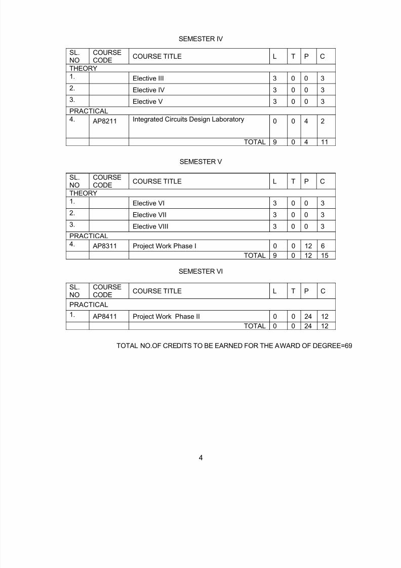
AP8152 ANALOG INTEGRATED CIRCUIT DESIGN L T P C3 0 0 3
OBJECTIVES:
Analog circuits play a very crucial role in all electronic systems and due to continuedminiaturization, many of the analog blocks are not getting realized in CMOS technology. Themost important building blocks of all CMOS analog ICs will be the topic of study in this course.
The basic principle of operation, the circuit choices and the tradeoffs involved in the MOS
transistor level design common to all analog CMOS ICs will be discussed in this course. The specific design issues related to single and multistage voltage, current and differential
amplifiers, their output and impedance issues, bandwidth, feedback and stability will be dealt within detail.
UNIT I SINGLE STAGE AMPLIFIERS 12Basic MOS physics and equivalent circuits and models, CS,, CG and Source Follower cascocde andfolded cascade configurations, differential amplifiers and current mirror configurations.
UNIT II HIGH FREQUENCY AND NOISE OF CHARACTERISTICS AMPLIFIERS 9
Current mirrors, cascode stages for current mirrors, current mirror loads for differential pairs. Miller
effect, association of poles with nodes, frequency response of CS, CG and source follower, cascodeand differential pair stages Statistical characteristics of noise, noise in single stage amplifiers, noise indifferential amplifiers.
UNIT III FEEDBACK AND OPERATIONAL AMPLIFIERS 9Properties and types of negative feedback circuits, effect of loading in feedback networks, operationalamplifier performance parameters, One-stage Op Amps, Two-stage Op Amps, Input range limitations,Gain boosting, slew rate, power supply rejection, noise in Op Amps.
UNIT IV STABILITY AND FREQUENCY COMPENSATION 9General considerations, Multipole systems, Phase Margin, Frequency Compensation, Compensationof two stage Op Amps, Slewing in two stage Op Amps, Other compensation techniques.
UNIT V BANDGAP REFERENCES 6Supply independent biasing, temperature independent references, PTAT current generation,Constant-Gm Biasing.
TOTAL: 45 PERIODS
REFERENCES:1. Behzad Razavi, “Design of Analog CMOS Integrated Circuits”, Tata McGraw Hill, 20012. Willey M.C. Sansen, “Analog Design Essentials”, Springer, 2006.3. Grebene, “Bipolar and MOS Analog Integrated circuit design”, John Wiley & sons,Inc., 2003.4. Phillip E.Allen, DouglasR.Holberg, “CMOS Analog Circuit Design”, Second edition, Oxford5. University Press, 20026. Recorded lecture available at http://www.ee.iitm.ac.in/~ani/ee5390/index.html
7. Jacob Baker “CMOS: Circuit Design, Layout, and Simulation, Third Edition”, Wiley IEEE Press2010 3rd Edition
OUTCOME:
Ability to carry out the design of single and two stage operational amplifiers and voltagereferences, and determine the device dimensions of each MOSFETs involved.

8/12/2019 10. M.E. Applied Electronics
http://slidepdf.com/reader/full/10-me-applied-electronics 8/40
8
AP8153 EMBEDDED SYSTEMS DESIGN L T P C 3 0 0 3
OBJECTIVES:
To expose the students to the fundamentals of embedded system design.
To enable the students to understand and use embedded computing platform.
To introduce networking principles in embedded devices.
To introduce RTOS in embedded devices.
UNIT I EMBEDDED PROCESSORS 9Embedded Computers, Characteristics of Embedded Computing Applications, Challenges inEmbedded Computing system design, Embedded system design process- Requirements,Specification, Architectural Design, Designing Hardware and Software Components, SystemIntegration, Formalism for System Design- Structural Description, Behavioural Description, DesignExample: Model Train Controller, ARM processor- processor and memory organization.
UNIT II EMBEDDED PROCESSOR AND COMPUTINGPLATFORM 9
Data operations, Flow of Control, SHARC processor- Memory organization, Data operations, Flow of
Control, parallelism with instructions, CPU Bus configuration, ARM Bus, SHARC Bus, Memorydevices, Input/output devices, Component interfacing, designing with microprocessor developmentand debugging, Design Example : Alarm Clock. Hybrid Architecture
UNIT III NETWORKS 9Distributed Embedded Architecture- Hardware and Software Architectures, Networks for embeddedsystems- I2C, CAN Bus, SHARC link supports, Ethernet, Myrinet, Internet, Network-Based design-Communication Analysis, system performance Analysis, Hardware platform design, Allocation andscheduling, Design Example: Elevator Controller.
UNIT IV REAL-TIME CHARACTERISTICS 9Clock driven Approach, weighted round robin Approach, Priority driven Approach, Dynamic Versus
Static systems, effective release times and deadlines, Optimality of the Earliest deadline first (EDF)algorithm, challenges in validating timing constraints in priority driven systems, Off-line Versus On-line scheduling.
UNIT V SYSTEM DESIGN TECHNIQUES 9Design Methodologies, Requirement Analysis, Specification, System Analysis and ArchitectureDesign, Quality Assurance, Design Example: Telephone PBX- System Architecture, Ink jet printer-Hardware Design and Software Design, Personal Digital Assistants, Set-top Boxes.
TOTAL: 45 PERIODSREFERENCES:1. Wayne Wolf, “Computers as Components: Principles of Embedded Computing System
Design”, Morgan Kaufman Publishers.2. Jane.W.S. Liu, “Real-Time systems”, Pearson Education Asia.3. C. M. Krishna and K. G. Shin, “Real-Time Systems” , McGraw-Hill, 19974. Frank Vahid and Tony Givargis, “Embedded System Design: A Unified5. Hardware/Software Introduction” , John Wiley & Sons.
OUTCOME:
Able to select and design suitable embedded systems for real world applications.
8/12/2019 10. M.E. Applied Electronics
http://slidepdf.com/reader/full/10-me-applied-electronics 9/40
9
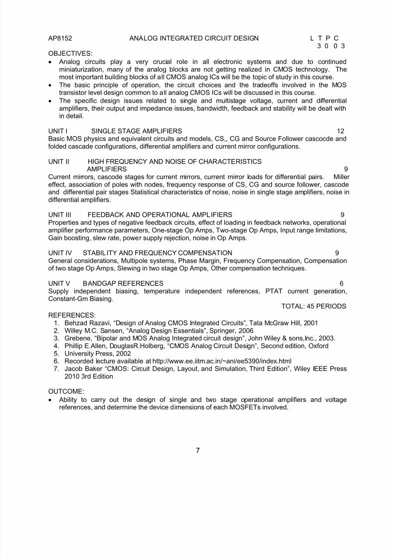
AP8154 STATISTICAL SIGNAL PROCESSING L T P C 3 0 0 3OBJECTIVES:
To introduce the basics of random signal processing
Concept wise introduction to estimation and prediction theory
To know about adaptive filtering and it’s applications
A brief overview of the processing of speech signals
UNIT I INTRODUCTION TO RANDOM SIGNAL PROCESSING 9Discrete Random Processes- Ensemble Averages, Stationary processes, Bias and Estimation,
Autocovariance, Autocorrelation, Parseval’s theorem, Wiener-Khintchine relation, White noise, PowerSpectral Density, Spectral factorization, Filtering Random Processes, Special types of RandomProcesses – ARMA, AR, MA – Yule-Walker equations.
UNIT II SPECTRAL ESTIMATION 9Estimation of spectra from finite duration signals, Nonparametric methods - Periodogram, Modifiedperiodogram, Bartlett, Welch and Blackman-Tukey methods, Parametric method, AR (p) spectralestimation and detection of Harmonic signals, MUSIC algorithm.
UNIT III LINEAR ESTIMATION AND PREDICTION 9Linear Prediction of Signals-Forward and Backward Predictions, Solution to Prony’s normal equation,Levinson Durbin Algorithm, Lattice filter realization of prediction error filters. Linear Minimum Mean-Square Error (LMMSE) Filtering: Wiener Hopf Equation, FIR Wiener filter, Noise Cancellation, CausalIIR Wiener filter, Noncausal IIR Wiener filter, Discrete Kalman filter
UNIT IV ADAPTIVE FILTERS 9FIR adaptive filters – adaptive filter based on steepest descent method- Widrow-Hopf LMS algorithm,Normalized LMS algorithm, Adaptive channel equalization, Adaptive echo cancellation, Adaptive noisecancellation, RLS adaptive algorithm.
UNIT V APPLICATION OVERVIEW-SPEECH PROCESSING 9
Speech Fundamentals: Articulatory Phonetics – Production and Classification of Speech Sounds; Acoustic Phonetics – acoustics of speech production; Short-term Fourier transform (STFT): overviewof Fourier representation, non-stationary signals, development of STFT, transform and filter-bankviews of STFT; Short time Homomorphic Filtering of Speech; Linear Prediction (LP) analysis: Basisand development, Levinson-Durbin’s method, normalized error, LPC spectrum.
TOTAL : 45 PERIODSREFERENCES1. Monson H. Hayes, “Statistical Digital Signal Processing and Modeling”, John Wiley and Sons,
Inc, Singapore, 2002.2. Lawrence Rabiner and Biing-Hwang Juang, “Fundamentals of Speech Recognition”,3. Pearson Education, 2003.4. Dimitris G. Manolakis and Vinay K .Ingle ,“Applied Digital Signal Processing”, Cambridge
University Press, 2011.5. L.R. Rabiner and R.W. Schafer, “Introduction to Digital Speech Processing” (Foundations and
Trends in Signal Processing), Now Publishers Inc., USA, 2007.
OUTCOMES:
Well equipped with the concepts of random signal processing
Prediction and Estimation concepts are well understood
Aware of adaptive filters and their applications
Gather basic knowledge about speech signal processing

8/12/2019 10. M.E. Applied Electronics
http://slidepdf.com/reader/full/10-me-applied-electronics 10/40
10
MA8163 ADVANCED APPLIED MATHEMATICS L T P C3 1 0 4
OBJECTIVES:
To encourage students to develop a working knowledge of the central ideas of linear algebra.
To study and understand the concepts of probability and random variable of the variousfunctions.
Understand the notion of a Markov chain, and how simple ideas of conditional probability andmatrices can be used to give a thorough and effective account of discrete-time Markov chains.
To formulate and construct a mathematical model for a linear programming problem in real lifesituation.
Introduce the Fourier Transform as an extension of Fourier techniques on periodic functionsand to solve partial differential equations.
UNIT I LINEAR ALGEBRA 9+3Vector spaces – norms – Inner Products – Eigenvalues using QR transformations – QR factorization -generalized eigenvectors – Canonical forms – singular value decomposition and applications -pseudo inverse – least square approximations --Toeplitz matrices and some applications.
UNIT II ONE DIMENSIONAL RANDOM VARIABLES 9+3
Random variables - Probability function – moments – moment generating functions and theirproperties – Binomial, Poisson, Geometric, Uniform, Exponential, Gamma and Normal distributions –Function of a Random Variable.
UNIT III RANDOM PROCESSES 9+3Classification – Auto correlation - Cross correlation - Stationary random process – Markov process –-Markov chain - Poisson process – Gaussian process.
UNIT IV LINEAR PROGRAMMING 9+3Formulation – Graphical solution – Simplex method – Two phase method - Transportation and
Assignment Models
UNIT V FOURIER TRANSFORM FOR PARTIAL DIFFERENTIAL EQUATION 9+3Fourier transforms: Definitions, properties-Transform of elementary functions, Dirac Delta functions –Convolution theorem – Parseval’s identity – Solutions to partial differential equations: Heat equations,Wave equations, Laplace and Poison’s equations.
TOTAL: 45+15:60 PERIODS
TEXT BOOKS:1. Bronson, R.Matrix Operation, Schaum’s outline series, McGraw Hill, New york (1989).2. Oliver C. Ibe, “Fundamentals of Applied Probability and Random Processes, Academic
Press, (An imprint of Elsevier), 2010.3. Taha H.A. “Operations Research: An introduction” Ninth Edition, Pearson Education, Asia, New
Delhi 2012.
4. Sankara Rao, K. “Introduction to partial differential equations” Prentice Hall of India, pvt, Ltd, NewDelhi, 1997.
REFERENCES:1. Andrews, L.C. and Philips. R. L. “Mathematical Techniques for engineering and scientists”,
Printice Hall of India, 2006.2. O’Neil P.V. “Advanced Engineering Mathematics”, (Thomson Asia pvt ltd, Singapore) 2007,
cengage learning India private limited.
8/12/2019 10. M.E. Applied Electronics
http://slidepdf.com/reader/full/10-me-applied-electronics 11/40
11
OUTCOME:
On successful completion of this course, all students will have developed knowledge andunderstanding in the fields of linear algebra, probability, stochastic process, linear programmingproblem and Fourier transform.
AP8111 EMBEDDED SYSTEMS DESIGN LABORATORY L T P C0 0 4 2
OBJECTIVES:
To give a hands on programming experience using microcontrollers.
To induce a programming skill in embedded system design using KEIL or RIDE “software.
1. Board development using 8051 microcontroller2. Assembly and High level language programs for 8051 - ports – timers –Seven Segment
display – UART – LCD interface3. RTOS – Simple task creation, Round Robin Scheduling, Preemptive scheduling,
Semaphores, Mailboxes.
4. Assembly and High level language programs for R8C - ports – timers -Seven Segmentdisplay – UART – LCD interface – Stepper Motor control
5. Assembly and High level language programs for MSP 430 - ports – timers - Seven Segmentdisplay – UART – LCD interface – Stepper Motor control
TOTAL: 60 PERIODSOUTCOME:
Ability to gain the skill of effective design of embedded systems using differentmicrocontrollers.
AP8251 DIGITAL CONTROL ENGINEERING L T P C 3 0 0 3
OBJECTIVES:
Students should acquire a fundamental understanding of digital control systems and design.
To teach the fundamental concepts of Digital Control systems and mathematical modeling of thesystem
To study the concept of time response and frequency response of the discrete time system
To teach the basics of stability analysis of the digital system
UNIT I PRINCIPLES OF CONTROLLERS 9Review of frequency and time response analysis and specifications of control systems, need for
controllers, continues time compensations, continues time PI, PD, PID controllers, digital PIDcontrollers.
UNIT II SIGNAL PROCESSING IN DIGITAL CONTROL 9 Sampling, time and frequency domain description, aliasing, hold operation, mathematical model ofsample and hold, zero and first order hold, factors limiting the choice of sampling rate,reconstruction.

8/12/2019 10. M.E. Applied Electronics
http://slidepdf.com/reader/full/10-me-applied-electronics 12/40
12
UNIT III MODELING AND ANALYSIS OF SAMPLED DATACONTROL SYSTEM 9
Difference equation description, Z-transform method of description, pulse transfer function, time andfrequency response of discrete time control systems, stability of digital control systems, Jury'sstability test, state variable concepts, first companion, second companion, Jordan canonicalmodels, discrete state variable models, elementary principles.
UNIT IV DESIGN OF DIGITAL CONTROL ALGORITHMS 9 Review of principle of compensator design, Z-plane specifications, digital compensator design usingfrequency response plots, discrete integrator, discrete differentiator, development of digital PIDcontroller, transfer function, design in the Z-plane.
UNIT V PRACTICAL ASPECTS OF DIGITAL CONTROL ALGORITHMS 9
Algorithm development of PID control algorithms, software implementation, implementation usingmicroprocessors and microcontrollers, finite word length effects, choice of data acquisition systems,microcontroller based temperature control systems, microcontroller based motor speed controlsystems.
TOTAL: 45 PERIODS
REFERENCES:1. M.Gopal, "Digital Control and Static Variable Methods", Tata McGraw Hill, New Delhi, 1997. 2. John J. D'Azzo, "Constantive Houpios, Linear Control System Analysis and Design", McGraw
Hill, 1995.3. Kenneth J. Ayala, "The 8051 Microcontroller- Architecture, Programming and Applications",
Penram International, 2nd Edition, 1996.
OUTCOMES:
Acquire working knowledge of discrete system science-related mathematics.
Design a discrete system, component or process to meet desired needs.
Identify, formulate and solve discrete control engineering problems.
Use the techniques, tools and skills related to discrete signals, computer science and
modern discrete control engineering in modern engineering practice Communicate system related concepts effectively
AP8252 DIGITAL IMAGE PROCESSING L T P C3 0 2 4
OBJECTIVES:
To understand the techniques for image enhancement.
To understand techniques for image segmentation.
To understand the techniques for compression.
OUTCOMES:
To be able to design and implement image enhancement schemes.
To be able to design and implement compression schemes.
To be able to design and implement restoration schemes.
To be able to design and implement segmentation schemes.

8/12/2019 10. M.E. Applied Electronics
http://slidepdf.com/reader/full/10-me-applied-electronics 13/40
13
UNIT I IMAGE REPRESENTATION (9+6)Image representation-Image Basis Functions- Two dimensional DFT- Discrete Cosine Transform-Walsh- Hadamard transform-Wavelet transform- Principal component analysis.
UNIT II IMAGE ENHANCEMENT AND RESTORATION (9+6) Gray level transformation techniques- Spatial domain techniques - Half toning, Median filtering,contrast stretching, Histogram Equalization- Frequency domain techniques - Weiner filtering-
Homomorphic filtering- PSFs for different forms of blur - noise models- color image processing.
UNIT III IMAGE SEGMENTATION (9+6)Segmentation - Similarity and dissimilarity methods- Thresholding - Edge based and Region basedmethods- Hough transform- Morphological operations - Clustering methods.
UNIT IV IMAGE COMPRESSION (9+6)Source coding techniques - Run length coding - Shannon-Fano coding- Huffman coding- Arithmeticcoding- LZW coding - Transform and Predictive compression methods - Vector quantization- casestudies - JPEG-MPEG.
UNIT V SIMULATION (9+6)
Implementation of Image processing algorithms - Image Enhancement - Restoration- Segmentation-Coding techniques- Applications.
TOTAL: 45+0+ 30 = 75 PERIODS REFERENCES:1. Gonzalez R. C. and Woods R.E., “Digital Image Processing”, 3rd Edition, Prentice-Hall, 2008.2. Jain A.K., “Fundamentals of Digital Image Processing”, PHI Learning Private Ltd., 1989.3. William K. Pratt, “Digital Image Processing”, John Wiley, 4th Edition, 2007.4. Sonka M, “Image Processing, Analysis and Machine Vision”, Vikas Publishing Home (Thomson)
2001.5. Schalkoff R.J., “Digital Image Processing & Computer Vision”, John Wiley & Sons, 1992.6. Richard O. Duda, Peter E. Hart and David G. Stork., “Pattern Classification”, Wiley, 2001.7. J.W. Woods, "Multidimensional Signal, Image, Video Processing and Coding", 2nd Edition,
Academic Press, 2012.
AP8211 INTEGRATED CIRCUITS DESIGN LABORATORY L T P C0 0 4 2
OBJECTIVES:
To introduce the programming concepts using Verilog or VHDL
To introduce the concepts of system design using FPGA
1. Design Entry Using VHDL or Verilog, examples for circuit descriptions using HDLlanguages sequential and concurrent statements.
2. Structural and behavioral descriptions, principles of operation and limitation of HDLsimulators. Examples of sequential and combinational logic design and simulation. Testvector generation.
3. CPLD – Board development. I/O interfacing, Analog interfacing, Real time applicationdevelopment.
4. FPGA- Board development. I/O interfacing, Analog interfacing, Real time applicationdevelopment.
5. System development using either PSPICE or FPGAs

8/12/2019 10. M.E. Applied Electronics
http://slidepdf.com/reader/full/10-me-applied-electronics 14/40
14
OUTCOMES:
Ability to develop FPGA based system design.
TOTAL : 60 PERIODS
AP8001 INTERNET WORKING AND MULTIMEDIA L T P C3 0 0 3OBJECTIVES:
To introduce the characteristics of text, graphics, video and speech.
To teach techniques for efficient transmission of multimedia signals over networks.
To introduce different network standards and parameters for quality of service.
UNIT I MULTIMEDIA NETWORKING 9Digital sound, video and graphics, basic multimedia networking, multimedia characteristics, evolutionof Internet services model, network requirements for audio/video transform, multimedia coding andcompression for text, image, audio and video.
UNIT II BROAD BAND NETWORK TECHNOLOGY 9 Broadband services, ATM and IP , IPV6, High speed switching, resource reservation, Buffermanagement, traffic shaping, caching, scheduling and policing, throughput, delay and jitterperformance.
UNIT III MULTICAST AND TRANSPORT PROTOCOL 9 Multicast over shared media network, multicast routing and addressing, scaping multicast and NBMAnetworks, Reliable transport protocols, TCP adaptation algorithm, RTP, RTCP.
UNIT IV MEDIA - ON – DEMAND 9 Storage and media servers, voice and video over IP, MPEG over ATM/IP, indexing synchronization ofrequests, recording and remote control.
UNIT V APPLICATIONS 9 MIME, Peer-to-peer computing, shared application, video conferencing, centralized and distributedconference control, distributed virtual reality, light weight session philosophy.
TOTAL: 45 PERIODSREFERENCES:1. Jon Crowcroft, Mark Handley, Ian Wakeman. Internetworking Multimedia, Harcourt Asia
Pvt.Ltd. Singapore, 1998.2. B.O. Szuprowicz, Multimedia Networking, McGraw Hill, NewYork. 19953. Tay Vaughan, Multimedia making it to work, 4ed,Tata McGrawHill, NewDelhi,2000.
OUTCOMES:
Capability to design efficient protocols for transmission of multimedia signals over networks.
Ability to analyze the network performance.
8/12/2019 10. M.E. Applied Electronics
http://slidepdf.com/reader/full/10-me-applied-electronics 15/40
15
AP8002 POWER ELECTRONICS L T P C3 0 0 3
OBJECTIVES:
To introduce electronic circuits for power control in industry and home applications
To design electronic circuits for efficient power control.
UNIT I CONVERTERS IN EQUILIBRIUM 9
Principles of Steady State Converter Analysis – Boost and Buck Converter Examples Steady-StateEquivalent Circuit Modeling, Losses, and Efficiency – Equivalent circuit model – complete circuitmodel - - Switch Realization- Switching loss - Converter Circuits – Circuit manipulation – Transformerisolation – Converter evaluation and design
UNIT II CONVERTER DYNAMICS AND CONTROL 9The Basic AC Modeling Approach - Averaging the Inductor and capacitor Waveforms - A Nonideal Flyback Converter - State-Space Averaging - Circuit Averaging and Averaged Switch Modeling - TheCanonical Circuit Model - Converter Transfer Functions - Analysis of Converter Transfer Functions -Graphical Construction of Impedances and Transfer Functions - Controller Design - Input FilterDesign- Current Programmed Control
UNIT III MAGNETICS 9Basic Magnetics Theory - Transformer Modeling - Loss Mechanisms in Magnetic Devices - EddyCurrents in Winding Conductors - Inductor Design - Filter Inductor Design Constraints - A Step-by-Step Procedure - Transformer Design - A Step-by-Step Transformer Design Procedure
UNIT IV MODERN RECTIFIERS AND POWER SYSTEM HARMONICS 9Power Phasors in Sinusoidal Systems - Harmonic Currents in Three-Phase Systems - AC LineCurrent Harmonic Standards - Line-Commutated Rectifiers - The Single-Phase Full-Wave Rectifier- The Three-Phase Bridge Rectifier - Phase Control - Pulse-Width Modulated Rectifiers -Realization of a Near-Ideal Rectifier - Control of the Current Waveform - Ideal Three-Phase Rectifiers
UNIT V RESONANT CONVERTERS 9
Resonant Conversion - Sinusoidal Analysis of Resonant Converters – Examples - Soft Switching -Soft-Switching Mechanisms of Semiconductor Devices - The Zero-Current-Switching Quasi-ResonantSwitch Cell - Resonant Switch Topologies - Soft Switching in PWM Converters
TOTAL: 45 PERIODS REFERENCES:1. Robert W. Erickson, Dragan Maksimovic,” Fundamentals of Power Electronics”, Kluwer
Academic Publishers, Second Edition, New York, Boston, Dordrecht, London, Moscow.2. Muhammad H Rashid, “ Power Electronics – Circuits, Devices and Applications”, Third
Edition, Prentice Hall of India, 2004.3. M.D. Singh, K.B.Khanchandani, “ Power Electronics”, Tata McGraw Hill, 1998.4. Ned Mohan, Tore M Undeland, William P. Robbins, Power Electronics, Converters,
Applications and Design”, John Wiley & Sons, 1994.
OUTCOME:
Ability to analyze and design electronic circuits for efficient power control.

8/12/2019 10. M.E. Applied Electronics
http://slidepdf.com/reader/full/10-me-applied-electronics 16/40
16
AP8003 SYNTHESIS AND OPTIMIZATION OF DIGITAL CIRCUITS L T P C 3 0 0 3
OBJECTIVES:
Deals with the basics of synthesis optimization, scheduling algorithms and resource allocationalgorithms for CAD synthesis.
To teach the logic level synthesis for combinational as well as sequential circuits and technologymapping.
UNIT I CIRCUITS AND HARDWARE MODELING 9Design of Microelectronic Circuits - Computer Aided Synthesis and optimization-Combinatorialoptimization-Boolean Algebra and Application-Hardware Modeling Languages –Compilation andBehavioral optimization.
UNIT II ARCHITECTURAL LEVEL SYNTHESIS AND OPTIMIZATION 9 The Fundamental Architectural synthesis Problems-Area and performance Estimation-Control unitsynthesis-synthesis of pipelined circuits.
UNIT III SCHEDULING ALGORITHMS AND RESOURCE SHARING 9Unconstrained Scheduling-ASAP Algorithm-ALAP Scheduling Algorithm- Scheduling with Resource
Constraints- Scheduling pipelined circuits-Sharing and binding for Dominated circuits-Area Binding-Concurrent Binding –Module selection problems-Structural testability.
UNIT IV LOGIC-LEVEL SYNTHESIS AND OPTIMIZATION 9Logic optimization Principles-Algorithms and logic Minimization –Encoding problems- Multiple-leveloptimization of logic networks-Algebraic and Boolean model-Algorithm for delay Evaluation-Rulebased logic optimization.
UNIT V SEQUENTIAL LOGIC OPTIMIZATION 9Sequential circuit -State Encoding-Minimization methods-Retiming- Finite state machine-testability forsynchronous circuits-Algorithm for library binding- Look-Up table - FPGA- Rule-based library binding.
TOTAL : 45 PERIODS REFERENCES: 1. Giovanni De Micheli, “Synthesis and optimization of Digital Circuits”, Tata McGraw-Hill, 2003.2. John Paul Shen, Mikko H. Lipasti, “Modern processor Design”, Tata McGraw Hill, 2003
OUTCOMES:
Capability to design, synthesize and optimize combinational as well as sequential circuits.
Ability to modify the digital designs for optimal performance using different scheduling andresource allocation algorithms.
AP8071 ADVANCED MICROPROCESSORS AND MICROCONTROLLERS L T P C3 0 0 3
OBJECTIVES:
To expose the students to the fundamentals of microprocessor architecture.
To introduce the advanced features in microprocessors and microcontrollers.
To enable the students to understand various microcontroller architectures.

8/12/2019 10. M.E. Applied Electronics
http://slidepdf.com/reader/full/10-me-applied-electronics 17/40
17
UNIT I MICROPROCESSOR ARCHITECTURE 9Instruction Set – Data formats –Addressing modes – Memory hierarchy –register file – Cache – Virtualmemory and paging – Segmentation- pipelining –the instruction pipeline – pipeline hazards –instruction level parallelism – reduced instruction set –Computer principles – RISC versus CISC.
UNIT II HIGH PERFORMANCE CISC ARCHITECTURE –PENTIUM 9
CPU Architecture- Bus Operations – Pipelining – Brach predication – floating point unit- OperatingModes –Paging – Multitasking – Exception and Interrupts – Instruction set – addressing modes –Programming the Pentium processor.
UNIT III HIGH PERFORMANCE RISC ARCHITECTURE – ARM 9Organization of CPU – Bus architecture –Memory management unit - ARM instruction set- ThumbInstruction set- addressing modes – Programming the ARM processor.
UNIT IV MOTOROLA 68HC11 MICROCONTROLLERS 9Instruction set addressing modes – operating modes- Interrupt system- RTC-Serial CommunicationInterface – A/D Converter PWM and UART.
UNIT V PIC MICROCONTROLLER 9
CPU Architecture – Instruction set – interrupts- Timers- I2C Interfacing –UART- A/D Converter –PWMand introduction to C-Compilers.
TOTAL: 45 PERIODS
REFERENCES:
1. Daniel Tabak , ‘’ Advanced Microprocessors” McGraw Hill.Inc., 19952. James L. Antonakos , “ The Pentium Microprocessor ‘’ Pearson Education, 1997.3. Steve Furber , ‘’ ARM System –On –Chip architecture “Addision Wesley , 2000.4. Gene .H.Miller .” Micro Computer Engineering ,” Pearson Education , 2003.5. John .B.Peatman , “ Design with PIC Microcontroller , Prentice hall, 1997.6. James L.Antonakos ,” An Introduction to the Intel family of Microprocessors ‘’ Pearson
Education 1999.
7. Barry.B.Breg,” The Intel Microprocessors Architecture, Programming and Interfacing“ ,PHI,2002.
8. Valvano "Embedded Microcomputer Systems" Thomson Asia PVT LTD first reprint 2001.Readings: Web links www.ocw.nit.edu www.arm.com
OUTCOME:
The student will be able to work with suitable microprocessor / microcontroller for a specific realworld application.
AP8072 ARTIFICIAL INTELLIGENCE AND OPTIMIZATION TECHNIQUES L T P C
3 0 0 3OBJECTIVES:To introduce the techniques of computational methods inspired by nature, such as neuralnetworks, genetic algorithms and other evolutionary computation systems, ant swarmoptimization, artificial immune systems, cellular automata, and multi-agent systems.
To present main rules underlying in these techniques.
To present selected case-studies.
To adopt these techniques in solving problems in the real world.
8/12/2019 10. M.E. Applied Electronics
http://slidepdf.com/reader/full/10-me-applied-electronics 18/40
18
UNIT I NEURAL NETWORKS 9 Neural Networks: Back Propagation Network, generalized delta rule, Radial Basis Function Network,interpolation and approximation RBFNS, comparison between RBFN and BPN, Support VectorMachines : Optimal hyperplane for linearly separable patterns, optimal hyperplane for non-linearlyseparable patterns, Inverse Modeling.
UNIT II FUZZY LOGIC SYSTEMS 9
Fuzzy Logic System: Basic of fuzzy logic theory , crisp and fuzzy sets, Basic set operation like union ,interaction , complement , T-norm , T-conorm , composition of fuzzy relations, fuzzy if-then rules ,fuzzy reasoning, Neuro-Fuzzy Modeling: Adaptive Neuro-Fuzzy Inference System (ANFIS) , ANFISarchitecture , Hybrid Learning Algorithm.
UNIT III EVOLUTIONARY COMPUTATION AND GENETIC ALGORITHMS 9
Evolutionary Computation (EC) – Features of EC – Classification of EC – Advantages – Applications.Genetic Algorithms: Introduction – Biological Background – Operators in GA-GA Algorithm –Classification of GA – Applications
UNIT IV ANT COLONY OPTIMIZATION 9 Ant Colony Optimization: Introduction – From real to artificial ants- Theoretical considerations –
Convergence proofs – ACO Algorithm – ACO and model based search – Application principles of ACO.
UNIT V PARTICLE SWARM OPTIMIZATION 9 Particle Swarm Optimization: Introduction – Principles of bird flocking and fish schooling – Evolutionof PSO – Operating principles – PSO Algorithm – Neighborhood Topologies – Convergence criteria –
Applications of PSO, Honey Bee Social Foraging Algorithms, Bacterial Foraging Optimization Algorithm.
TOTAL: 45 PERIODS
REFERENCES:1. Christopher M. Bishop, “Neural Networks for Pattern Recognition”, Oxford University
Press
2. Nello Cristianini, John Shawe-Taylor, "An Introduction to Support Vector Machines and OtherKernel-based Learning Methods”,Cambridge University Press.
3. Jyh-Shing Roger Jang, Chuen-Tsai Sun, Eiji Mizutani,” Neuro-fuzzy and4. soft computing: a computational approach to learning and machine intelligence”, Prentice Hall of
India, New Delhi.5. H.J. Zimmermann, “Fuzzy Set Theory and its Applications”, Springer.6. David E. Goldberg, “Genetic Algorithms in search, Optimization & Machine Learning”, Pearson
Education.7. Kenneth A DeJong,“Evolutionary Computation A Unified Approach”, Prentice Hall of India, New
Delhi.8. Marco Dorigo and Thomas Stutzle, “Ant Colony optimization”, Prentice Hall of India, New Delhi.9. N P Padhy, Artificial Intelligence and Intelligent Systems, Oxford University Press, 2005
10. Engelbrecht, A.P. Fundamentals of Computational Swarm Intelligence, Wiley.
OUTCOMES:
An understanding of the fundamental Computational Intelligence models
Understanding the concepts of neural networks, genetic algorithms, fuzzy neuralnetworks, and ant colony optimization algorithms
Application of computational Intelligence techniques to classification, pattern recognition,prediction, rule extraction, and optimization problems.
8/12/2019 10. M.E. Applied Electronics
http://slidepdf.com/reader/full/10-me-applied-electronics 19/40
19
AP8073 DESIGN AND ANALYSIS OF ALGORITHMS L T P C
3 0 0 3
OBJECTIVES:
Discusses the algorithmic complexity parameters and the basic algorithmic design techniques.
To discuss the graph algorithms, algorithms for NP Completeness Approximation Algorithms andNP Hard Problems.
UNIT I INTRODUCTION 9Polynomial and Exponential algorithms, big "oh" and small "oh" notation, exact algorithms andheuristics, direct / indirect / deterministic algorithms, static and dynamic complexity, stepwiserefinement.
UNIT II DESIGN TECHNIQUES 9 Subgoals method, working backwards, work tracking, branch and bound algorithms for travelingsalesman problem and knapsack problem, hill climbing techniques, divide and conquer method,dynamic programming, greedy methods.
UNIT III SEARCHING AND SORTING 9 Sequential search, binary search, block search, Fibonacci search, bubble sort, bucket sorting, quicksort, heap sort, average case and worst case behavior
UNIT IV GRAPH ALGORITHMS 9 Minimum spanning, tree, shortest path algorithms, R-connected graphs, Even's and Kleitman'salgorithms,max-flow min cut theorem, Steiglitz's link deficit algorithm.
UNIT V SELECTED TOPICS 9 NP Completeness Approximation Algorithms, NP Hard Problems, Strasseu's Matrix Multiplication
Algorithms, Magic Squares, Introduction To Parallel Algorithms and Genetic Algorithms, Monte-CarloMethods, Amortised Analysis.
TOTAL : 45 PERIODS
REFERENCES:
1. Sara Baase, "Computer Algorithms : Introduction to Design and Analysis", AddisonWesley,1988.
2. T.H.Cormen, C.E.Leiserson and R.L.Rivest, "Introduction to Algorithms", McGraw Hill,1994.
3. E.Horowitz and S.Sahni, "Fundamentals of Computer Algorithms", GalgotiaPublications, 1988.
4. D.E.Goldberg, "Genetic Algorithms: Search Optimization and Machine Learning", AddisonWesley, 1989.
OUTCOMES:
Will be able to apply the suitable algorithm according to the given optimization problem. Ability to modify the algorithms to refine the complexity parameters.

8/12/2019 10. M.E. Applied Electronics
http://slidepdf.com/reader/full/10-me-applied-electronics 20/40
20
AP8074 DSP INTEGRATED CIRCUITS L T P C3 0 0 3
OBJECTIVES:
To familiarize the concept of DSP and DSP algorithms.
Introduction to Multirate systems and finite word length effects
To know about the basic DSP processor architectures and the synthesis of the processingelements
To gather an idea about the VLSI circuit layout design styles.
UNIT I INTRODUCTION TO DSP INTEGRATED CIRCUITS 9Introduction to Digital signal processing, Sampling of analog signals, Selection of sample frequency,Signal- processing systems, Frequency response, Transfer functions, Signal flow graphs, Filterstructures, Adaptive DSP algorithms, DFT-The Discrete Fourier Transform, FFT-The Fast FourierTransform Algorithm, Image coding, Discrete cosine transforms, Standard digital signal processors,
Application specific IC’s for DSP, DSP systems, DSP system design, Integrated circuit design.
UNIT II DIGITAL FILTERS AND FINITE WORD LENGTH EFFECTS 9FIR filters, FIR filter structures, FIR chips, IIR filters, Specifications of IIR filters, Mapping of analogtransfer functions, Mapping of analog filter structures, Multirate systems, Interpolation with an integer
factor L, Sampling rate change with a ratio L/M, Multirate filters. Finite word length effects -Parasiticoscillations, Scaling of signal levels, Round-off noise, Measuring round-off noise, Coefficientsensitivity, Sensitivity and noise.
UNIT III DSP ARCHITECTURES 9DSP system architectures, Standard DSP architecture-Harvard and Modified Harvard architecture.TMS320C54x and TMS320C6x architecture, Motorola DSP56002 architecture, Ideal DSParchitectures, Multiprocessors and multicomputers, Systolic and Wave front arrays, Shared memoryarchitectures.
UNIT IV SYNTHESIS OF DSP ARCHITECTURES AND ARITHMETIC UNIT 9Synthesis: Mapping of DSP algorithms onto hardware, Implementation based on complex PEs,Shared memory architecture with Bit – serial PEs.
Arithmetic Unit : Conventional number system, Redundant Number system, Residue Number System,Bit-parallel and Bit-Serial arithmetic, Digit Serial arithmetic, CORDIC Algorithm, Basic shiftaccumulator, Reducing the memory size, Complex multipliers, Improved shift-accumulator.
UNIT V CASE STUDY-INTEGRATED CIRCUIT DESIGN 9 Layout of VLSI circuits, Layout Styles, Case Study : FFT processor, DCT processor and Interpolator.
TOTAL: 45 PERIODSREFERENCES:1. Lars Wanhammer, “DSP Integrated Circuits”, Academic press, New York, 1999.2. John J. Proakis, Dimitris G. Manolakis, “Digital Signal Processing”, Pearson Education,
2002.3. B.Venkatramani, M.Bhaskar, “Digital Signal Processors”, Tata McGraw-Hill, 2002.4. Emmanuel C. Ifeachor, Barrie W. Jervis, “ Digital signal processing – A practical
approach”, Tata McGraw-Hill, 2002.5. Keshab K.Parhi, “VLSI Digital Signal Processing Systems design and Implementation”,
John Wiley & Sons, 1999.
8/12/2019 10. M.E. Applied Electronics
http://slidepdf.com/reader/full/10-me-applied-electronics 21/40
21
OUTCOMES:
Get to know about the Digital Signal Processing concepts and it’s algorithms
Get an idea about finite word length effects in digital filters
Concept behind multirate systems is understood.
Get familiar with the DSP processor architectures and how to perform synthesis ofprocessing elements
Acquire an general idea about VLSI circuit layout design aspects
AP8075 ELECTROMAGNETIC INTERFERENCE AND COMPATIBIL ITY IN L T P CSYSTEM DESIGN 3 0 0 3
OBJECTIVES:
To introduce concepts related to Electromagnetic interference in PCBs
To teach solutions for minimizing EMI in PCBs
To teach EMI standards in the design of PCBs
UNIT I EMI/EMC CONCEPTS 9EMI-EMC definitions and Units of parameters; Sources and victim of EMI; Conducted and RadiatedEMI Emission and Susceptibility; Transient EMI, ESD; Radiation Hazards.
UNIT II EMI COUPLING PRINCIPLES 9 Conducted, radiated and transient coupling; Common ground impedance coupling; Common modeand ground loop coupling; Differential mode coupling ; Near field cable to cable coupling, cross talk ;Field to cable coupling; Power mains and Power supply coupling.
UNIT III EMI CONTROL TECHNIQUES 9Shielding, Filtering, Grounding, Bonding, Isolation transformer, Transient suppressors, Cable routing,
Signal control.
UNIT IV EMC DESIGN OF PCBS 9Component selection and mounting; PCB trace impedance; Routing; Cross talk control; Powerdistribution decoupling; Zoning; Grounding; VIAs connection; Terminations.
UNIT V EMI MEASUREMENTS AND STANDARDS 9 Open area test site; TEM cell; EMI test shielded chamber and shielded ferrite lined anechoicchamber; Tx/Rx Antennas, Sensors, Injectors/Couplers, and coupling factors; EMI Rx and spectrumanalyzer; Civilian standards - CISPR, FCC, IEC, EN; Military standards-MIL461E/462.
TOTAL : 45 PERIODS
REFERENCES:1. V.P.Kodali, “Engineering EMC Principles, Measurements and Technologies”, IEEE Press,
Newyork, 1996.
2. Henry W.Ott.,”Noise Reduction Techniques in Electronic Systems”, A Wiley Inter Science
Publications, John Wiley and Sons, Newyork, 1988.
3. Bemhard Keiser, “Principles of Electromagnetic Compatibility”, 3rd Ed, Artech house,
Norwood, 1986.
4. C.R.Paul,”Introduction to Electromagnetic Compatibility” , John Wiley and Sons, Inc, 1992.
5. Don R. J.White Consultant Incorporate, “Handbook of EMI/EMC”, Vol I-V, 1988.

8/12/2019 10. M.E. Applied Electronics
http://slidepdf.com/reader/full/10-me-applied-electronics 22/40
22
OUTCOMES:
Ability to analyze Electromagnetic interference effects in PCBs
Ability to propose solutions for minimizing EMI in PCBs’’
AP8076 HARDWARE SOFTWARE CO-DESIGN L T P C3 0 0 3
OBJECTIVES:
The students will learn various design steps starting from system specifications tohardware/software implementation and will experience process optimization while consideringvarious design decisions.
Students will gain design experience with project/case studies using contemporary high-levelmethods and tools.
UNIT I SYSTEM SPECIFICATION AND MODELLING 9Embedded Systems , Hardware/Software Co-Design , Co-Design for System Specification and
Modelling Co-Design for Heterogeneous Implementation - Processor Synthesis , Single-Processor Architectures with one ASIC , Single-Processor Architectures with many ASICs, Multi-Processor Architectures , Comparison of Co-Design Approaches , Models of Computation ,Requirements forEmbedded System Specification .
UNIT II HARDWARE/SOFTWARE PARTITIONING 9The Hardware/Software Partitioning Problem, Hardware-Software Cost Estimation, Generation of thePartitioning Graph , Formulation of the HW/SW Partitioning Problem, Optimization , HW/SWPartitioning based on Heuristic Scheduling, HW/SW Partitioning based on Genetic Algorithms .
UNIT III HARDWARE/SOFTWARE CO-SYNTHESIS 9The Co-Synthesis Problem, State-Transition Graph, Refinement and Controller Generation,
Distributed System Co-Synthesis
UNIT IV PROTOTYPING AND EMULATION 9Introduction, Prototyping and Emulation Techniques , Prototyping and Emulation Environments,Future Developments in Emulation and Prototyping ,Target Architecture- Architecture SpecializationTechniques ,System Communication Infrastructure, Target Architectures and Application SystemClasses, Architectures for Control-Dominated Systems, Architectures for Data-Dominated Systems,Mixed Systems and Less Specialized Systems
UNIT V DESIGN SPECIFICATION AND VERIFICATION 9Concurrency, Coordinating Concurrent Computations, Interfacing Components, Verification ,Languages for System-Level Specification and Design System-Level Specification ,Design
Representation for System Level Synthesis, System Level Specification Languages, HeterogeneousSpecification and Multi-Language Co-simulationTOTAL : 45 PERIODS
REFERENCES:1. Ralf Niemann, “Hardware/Software Co-Design for Data Flow Dominated Embedded
Systems”, Kluwer Academic Pub, 1998.2. Jorgen Staunstrup , Wayne Wolf ,”Hardware/Software Co-Design: Principles and Practice” ,
Kluwer Academic Pub,1997.3. Giovanni De Micheli , Rolf Ernst Morgon,” Reading in Hardware/Software Co-Design
“Kaufmann Publishers,2001.

8/12/2019 10. M.E. Applied Electronics
http://slidepdf.com/reader/full/10-me-applied-electronics 23/40
23
OUTCOMES:On completion of the course, a student should be able:
To understand and to apply design methodologies
To appreciate the fundamental building blocks of the using hardware and software co-design andrelated implementation and testing environments and techniques and their inter-relationships
To be familiar with modern hardware/software tools for building prototypes
To demonstrate practical competence in these areas.
AP8077 HIGH SPEED SWITCHING ARCHITECTURES L T P C3 0 0 3
OBJECTIVES:
To enable the student to understand the basics of switching technologies and theirimplementation LANs, ATM networks and IP networks.
To enable the student to understand the different switching architectures and queuingstrategies and their impact on the blocking performances.
To expose the student to the advances in packet switching architectures and IP addressing
and switching solutions and approaches to exploit and integrate the best features ofdifferent architectures for high speed switching.
UNIT I LAN SWITCHING TECHNOLOGY 9 Switching Concepts, LAN Switching, switch forwarding techniques - cut through and store andforward, Layer 3 switching, Loop Resolution, Switch Flow control, virtual LANs.
UNIT II ATM SWITCHING ARCHITECTURES 9 Blocking networks - basic - and- enhanced banyan networks, sorting networks - merge sorting,
re-arrangable networks - full-and- partial connection networks, non blocking networks -Recursive network construction, comparison of non-blocking network, Switching with deflectionrouting - shuffle switch, tandem banyan switch.
UNIT III QUEUES IN ATM SWITCHES 9Internal Queueing -Input, output and shared queueing, multiple queueing networks – combinedInput, output and shared queueing - performance analysis of Queued switches.
UNIT IV PACKET SWITCHING ARCHITECTURES 9 Architectures of Internet Switches and Routers- Bufferless and buffered Crossbar switches,Multi-stage switching, Optical Packet switching; Switching fabric on a chip; Internally bufferedCrossbars.
UNIT V IP SWITCHING 9 Addressing model, IP Switching types - f low driven and topology driven solutions, IP Over ATM
address and next hop resolution, multicasting, Ipv6 over ATM.
TOTAL : 45 PERIODS
8/12/2019 10. M.E. Applied Electronics
http://slidepdf.com/reader/full/10-me-applied-electronics 24/40
24
REFERENCES:1. Achille Pattavina, “Switching Theory: Architectures and performance in Broadband ATM
networks ",John Wiley & Sons Ltd, New York. 19982. Rich Siefert, Jim Edwards, “The All New Switch Book – The Complete Guide to LAN
Switching Technology”, Wiley Publishing, Inc., Second Edition, 2008.
3. Elhanany M. Hamdi, “High Performance Packet Switching architectures”, SpringerPublications, 2007.
4. Christopher Y Metz, “Switching protocols & Architectures”, McGraw - Hill ProfessionalPublishing, NewYork.1998.
5. Rainer Handel, Manfred N Huber, Stefan Schroder, “ATM Networks - Concepts Protocols, Applications”, 3rd Edition, Addison Wesley, New York. 1999.
OUTCOMES:
The student would be able to identify suitable switch architectures for a specified networkingscenario and demonstrate its blocking performance.
The student would be in a position to apply his knowledge of switching technologies, architecturesand buffering strategies for designing high speed communication networks and analyze theirperformance.
AP8078 INTRODUCTION TO MEMS SYSTEM DESIGN L T P C3 0 0 3
OBJECTIVES:
To give them hands on experience for the fabrication processes using micro-fabrication tools inthe clean room.
Briefly review on various application fields of the micro sensors, MEMS, and smart devices. Thematerials and the processes required to make different kinds of the micro devices.
The standard microelectronics technology to produce ultra large-scale integrated circuits andpackage them will also be reviewed. The new techniques that have been developed to make microsensors and micro actuators, such as bulk and surface silicon micromachining will be followed.
The fabrication process will include metal thin film e-beam evaporation, dielectric thin film growingusing oxidation tube furnace, electrochemical deposition, and various kinds of chemicalprocesses.
UNIT I INTRODUCTION TO MEMS 9MEMS and Microsystems, Miniaturization, Typical products, Micro sensors, Micro actuation, MEMSwith micro actuators, Micro accelorometers and Micro fluidics, MEMS materials, Micro fabrication
UNIT II MECHANICS FOR MEMS DESIGN 9Elasticity, Stress, strain and material properties, Bending of thin plates, Spring configurations,
torsional deflection, Mechanical vibration, Resonance, Thermo mechanics – actuators, force andresponse time, Fracture and thin film mechanics.
UNIT III ELECTRO STATIC DESIGN 9Electrostatics: basic theory, electro static instability. Surface tension, gap and finger pull up, Electrostatic actuators, Comb generators, gap closers, rotary motors, inch worms, Electromagnetic actuators.bistable actuators.

8/12/2019 10. M.E. Applied Electronics
http://slidepdf.com/reader/full/10-me-applied-electronics 25/40
25
UNIT IV CIRCUIT AND SYSTEM ISSUES 9Electronic Interfaces, Feed back systems, Noise , Circuit and system issues, Case studies –Capacitive accelerometer, Peizo electric pressure sensor, Modelling of MEMS systems, CAD forMEMS.
UNIT V INTRODUCTION TO OPTICAL AND RF MEMS 9Optical MEMS, - System design basics – Gaussian optics, matrix operations, resolution. Case
studies, MEMS scanners and retinal scanning display, Digital Micro mirror devices. RF Memes –design basics, case study – Capacitive RF MEMS switch, performance issues.
TOTAL : 45 PERIODS TEXT BOOKS:
1. Stephen Santuria,” Microsystems Design”, Kluwer publishers, 2000.
REFERENCES:1. Nadim Maluf,” An introduction to Micro electro mechanical system design”, Artech
House, 20002. Mohamed Gad-el-Hak, editor,” The MEMS Handbook”, CRC press Baco Raton, 2000.3. Tai Ran Hsu,” MEMS & Micro systems Design and Manufacture” Tata McGraw Hill, New
Delhi, 2002.
OUTCOMES:On completion of the module students should:
Be able to extend the principles of micro fabrication to the development of micromechanicaldevices and the design of micro systems
Understand the principles of energy transduction, sensing and actuation on a microscopicscale.
Appreciate the effects of scaling, and the similarities and differences betweenmicromechanical assemblies and macroscopic machines.
Be able to analyse and model the behaviour of micro electromechanical devices andsystems
AP8079 NONLINEAR SIGNAL PROCESSING L T P C3 0 0 3
OBJECTIVES:
To introduce nonlinear filtering concepts, algorithms and architectures
To apply these algorithms in Image processing
UNIT I INTRODUCTION TO NONLINEAR FILTERS AND STATISTICAL
PRELIMINARIES 8 Nonlinear filters – measure of robustness – M estimators – L estimators – R estimators – orderstatistics – median filter and their characteristics – impulsive noise filtering by median filters –Recursive and weighted median filters – stock filters.
UNIT II NON LINEAR DIGITAL SIGNAL PROCESSING BASED ON ORDERSTATISTICS 7
Time ordered nonlinear filters – rank ordered nonlinear filters – max/median filtering – median hybridfilters – characteristics of ranked order filters – L filters – M filters – R filters – comparison.

8/12/2019 10. M.E. Applied Electronics
http://slidepdf.com/reader/full/10-me-applied-electronics 26/40
26
UNIT III ADAPTIVE NONLINEAR AND POLYNOMIAL FILTERS 10 Definition of polynomial filters – Wiener filters – robust estimation of scale – Adaptive filter based onlocal statistics – Decision directed filters – Adaptive L filters – Comparison of adaptive nonlinear filters
– Neural networks for nonlinear filter
UNIT IV ALGORITHMS AND ARCHITECTURES 10Sorting and selection algorithm – running median algorithm – fast structures for median and order
statistics filtering – systolic array implementation – Wavefront array implementation – quadratic digitalfilters implementation
UNIT V APPLICATIONS OF NONLINEAR FILTERS 10 Power spectrum analysis – Morphological image processing – nonlinear edge detection impulsenoise rejection in image and bio signals – two component image filtering – speech processing
TOTAL : 45 PERIODSREFERENCES:1. Loannis Pitas, Anastarios, N.Venetsanopoulos, Nonlinear Digital filters – Principles and
Applications Kluwer Academic Publishers, 19902. Jaakko T.Astola, Jaakko Astola Kuosmanen, Fundamentals of Nonlinear Digital filtering ,
CRC Press LLC, 19973. Wing Kuen Ling, Nonlinear Digital filters: Analysis and Applications , Elsevier Science &
Tech. 20074. GonzaloR. Arce, Nonlinear Signal Processing – A statistical approach , Wiley Publishers,
2005
OUTCOMES:
Know and understand the optimal solution to the filtering problem
Ability to solve linear and nonlinear filtering problem as applied to signal and imageprocessing
AP8080 RF SYSTEM DESIGN L T P C3 0 0 3
OBJECTIVES:
The CMOS RF Front End (RFE) is a very crucial building block and in all of wireless and manyhigh frequency wire-line systems. The RFE has few important building blocks within including theLow Noise Amplifiers, Phase Locked Loop Synthesizers, Mixers, Power Amplifiers, andimpedance matching circuits.
The present course will introduce the principles of operation and design principles associated with
these important blocks. The course will also provide and highlight the appropriate digital communication related design
objectives and constraints associated with the RFEs
UNITI , , ,, , , ,CMOS PHYSICS, TRANSCEIVER SPECIFICATIONS AND ARCHITECTURES 9
Introduction to MOSFET Physics, Noise: Thermal, shot, flicker, popcorn noise, Two port Noise theory,Noise Figure, THD, IP2, IP3, Sensitivity, SFDR, Phase noise - Specification distribution over acommunication link, Homodyne Receiver, Heterodyne Receiver, Image reject, Low IF Receiver
Architectures Direct upconversion Transmitter, Two step upconversion Transmitter

8/12/2019 10. M.E. Applied Electronics
http://slidepdf.com/reader/full/10-me-applied-electronics 27/40
27
UNIT II IMPEDANCE MATCHING AND AMPLIFIERS 9 S-parameters with Smith chart, Passive IC components, Impedance matching networks, CommonGate, Common Source Amplifiers, OC Time constants in bandwidth estimation and enhancement,High frequency amplifier design, Power match and Noise match, Single ended and Differential LNAs,Terminated with Resistors and Source Degeneration LNAs.
UNIT III FEEDBACK SYSTEMS AND POWER AMPLIFIERS 9
Stability of feedback systems: Gain and phase margin, Root-locus techniques, Time and Frequencydomain considerations , Compensation, General model – Class A, AB, B, C, D, E and F amplifiers,Power amplifier Linearisation Techniques, Efficiency boosting techniques, ACPR metric, Designconsiderations
UNIT IV MIXERS AND OSCILLATORS 9 Mixer characteristics, Non-linear based mixers, Quadratic mixers, Multiplier based mixers, Singlebalanced and double balanced mixers, subsampling mixers, Oscillators describing Functions, Colpittsoscillators Resonators, Tuned Oscillators, Negative resistance oscillators, Phase noise.
UNIT V PLL AND FREQUENCY SYNTHESIZERS 9 Linearised Model, Noise properties, Phase detectors, Loop filters and Charge pumps, Integer-N
frequency synthesizers, Direct Digital Frequency synthesizers.TOTAL : 45 PERIODS
TEXT BOOKS1. T.Lee, “Design of CMOS RF Integrated Circuits”, Cambridge, 2004.2. B.Razavi, “RF Microelectronics”, Pearson Education, 1997.3. Jan Crols, Michiel Steyaert, “CMOS Wireless Transceiver Design”, Kluwer Academic4. Publishers, 1997.5. B.Razavi, “Design of Analog CMOS Integrated Circuits”, McGraw Hill, 20016. Recorded lectures and notes available at. http://www.ee.iitm.ac.in/~ani/ee6240/
OUTCOMES:
The student after completing this course must be able to translate the top level Wireless
Communications system specifications into block level specifications of the RFE. The student should also able to carry out transistor level design of the entire RFE.
AP8081 SELECTED TOPICS IN ASIC DESIGN L T P C3 0 0 3
OBJECTIVES:
The course focuses on the semi custom IC Design and introduces the principles of designlogic cells, I/O cells and interconnect architecture, with equal importance given to FPGA and
ASIC styles.
The entire FPGA and ASIC design flow is dealt with from the circuit and layout design point ofview.
UNIT I INTRODUCTION TO ASICS, CMOS LOGIC AND ASICLIBRARY DESIGN 9
Types of ASICs - Design flow - CMOS transistors - Combinational Logic Cell – Sequential logic cell -Data path logic cell - Transistors as Resistors - Transistor Parasitic Capacitance- Logical effort.

8/12/2019 10. M.E. Applied Electronics
http://slidepdf.com/reader/full/10-me-applied-electronics 28/40
28
UNIT II PROGRAMMABLE ASICS, PROGRAMMABLE ASIC LOGIC CELLS AND PROGRAMMABLE ASIC I/O CELLS 9
Anti fuse - static RAM - EPROM and EEPROM technology - Actel ACT - Xilinx LCA –Altera FLEX - Altera MAX DC & AC inputs and outputs - Clock & Power inputs - Xilinx I/O blocks.
UNIT III PROGRAMMABLE ASIC ARCHITECUTRE 9 Architecture and configuration of Spartan / Cyclone and Virtex / Stratix FPGAs – Micro-Blaze / Nios
based embedded systems – Signal probing techniques.
UNIT IV LOGIC SYNTHESIS, PLACEMENT AND ROUTING 9Logic synthesis - ASIC floor planning- placement and routing – power and clocking strategies.
UNIT V HIGH PERFORMANCE ALGORITHMS FOR ASICS/ SOCS.SOC CASE STUDIES 9
DAA and computation of FFT and DCT. High performance filters using delta-sigma modulators. CaseStudies: Digital camera, SDRAM, High speed data standards.
TOTAL: 45 PERIODSREFERENCES:
1. M.J.S.Smith, " Application - Specific Integrated Circuits", Pearson,20032. Steve Kilts, “Advanced FPGA Design,” Wiley Inter-Science.3. Roger Woods, John McAllister, Dr. Ying Yi, Gaye Lightbod, “FPGA-based Implementation of
Signal Processing Systems”, Wiley, 20084. Mohammed Ismail and Terri Fiez, "Analog VLSI Signal and Information Processing ", Mc Graw
Hill, 1994.5. Douglas J. Smith, HDL Chip Design, Madison, AL, USA: Doone Publications, 1996.6. Jose E. France, Yannis Tsividis, "Design of Analog - Digital VLSI Circuits for Telecommunication
and Signal Processing", Prentice Hall, 1994
OUTCOMES: After completing this course,
The student would have gained knowledge in the circuit design aspects at the next transistor andblock level abstractions of FPGA and ASIC design. In combination with the course on CAD forVLSI, the student would have gained sufficient theoretical knowledge for carrying out FPGA and
ASIC designs.
AP8082 SELECTED TOPICS IN IC DESIGN L T P C3 0 0 3
OBJECTIVES:
This course deals with the supply circuit modules which are crucial modules in an IC design.
Clock generation circuits play a major role in High Speed Broad Band Communication circuits,High Speed I/O’s, Memory modules and Data Conversion Circuits.
This course focuses on the design aspect of Clock Generation circuits and their designconstraints.
UNIT I VOLTAGE AND CURRENT REFERENCES 9Current Mirrors, Self Biased Current Reference, startup circuits, VBE based Current Reference, VTBased Current Reference, Band Gap Reference , Supply Independent Biasing, TemperatureIndependent Biasing, PTAT Current Generation, Constant Gm Biasing

8/12/2019 10. M.E. Applied Electronics
http://slidepdf.com/reader/full/10-me-applied-electronics 29/40
29
UNIT II LOW DROP OUT REGULATORS 9 Analog Building Blocks, Negative Feedback, AC Design, Noise and Noise Reduction Techniques,Stability, LDO Efficiency, LDO Current Source, LDO Current Source Using Opamp.
UNIT III OSCILLATOR FUNDAMENTALS 9General considerations, Ring oscillators, LC oscillators, Colpitts Oscillator, Jitter and Phase noise inRing Oscillators, Impulse Sensitivity Function for Ring Oscillators, Phase Noise in Differential LC
Oscillators.
UNIT IV PHASE LOCK LOOPS 9PLL Fundamental, PLL stability, Noise Performance, Charge-Pump PLL Topology, CPPLL Buildingblocks, Jitter and Phase Noise performance.
UNIT V CLOCK AND DATA RECOVERY 9CDR Architectures, Tias and Limiters, CMOS Interface, Linear Half Rate CMOS CDR Circuits, Widecapture Range CDR Circuits.
TOTAL: 45 PERIODS
REFERENCES
1. Gabriel. A. Rincon-Mora, "Voltage references from diode to precision higher order
bandgap circuits”,John wiley & Sons, Inc 2002.2. Floyd M. Gardner ,”Phase LocK Techniques” John wiley & Sons, Inc 2005.3. High Speed Clock and Data Recovery, High-performance Amplifiers Power4. Management “ springer, 2008.5. Behzad Razavi, “Design of Integrated circuits for Optical Communications”, McGraw Hill, 2003.
OUTCOMES: This course provides the essential know how to a designer to construct Supply reference circuits andClock Generation Circuits for given design specifications and aids the designer to understand thedesign specifications related to Supply and Clock Generation Circuits.
AP8083 SIGNAL INTEGRITY FOR HIGH SPEED DESIGN L T P C3 0 0 3
OBJECTIVES:
To identify sources affecting the speed of digital circuits.
To introduce methods to improve the signal transmission characteristics
UNIT I SIGNAL PROPAGATION ON TRANSMISSION LINES 9Transmission line equations, wave solution, wave vs. circuits, initial wave, delay time, Characteristicimpedance , wave propagation, reflection, and bounce diagrams Reactive terminations – L, C , static
field maps of micro strip and strip line cross-sections, per unit length parameters, PCB layer stackupsand layer/Cu thicknesses, cross-sectional analysis tools, Zo and Td equations for microstrip andstripline Reflection and terminations for logic gates, fan-out, logic switching , input impedance into atransmission-line section, reflection coefficient, skin-effect, dispersion
UNIT II MULTI-CONDUCTOR TRANSMISSION LINES AND CROSS-TALK 9Multi-conductor transmission-lines, coupling physics, per unit length parameters, Near and far-endcross-talk, minimizing cross-talk (stripline and microstrip) Differential signalling, termination, balancedcircuits ,S-parameters, Lossy and Lossles models

8/12/2019 10. M.E. Applied Electronics
http://slidepdf.com/reader/full/10-me-applied-electronics 30/40
30
UNIT III NON-IDEAL EFFECTS 9Non-ideal signal return paths – gaps, BGA fields, via transitions , Parasitic inductance and
capacitance , Transmission line losses – Rs, tanδ, routing parasitic, Common-mode current,differential-mode current , Connectors
UNIT IV POWER CONSIDERATIONS AND SYSTEM DESIGN 9SSN/SSO , DC power bus design , layer stack up, SMT decoupling ,, Logic families, power
consumption, and system power delivery , Logic families and speed Package types and parasitic,SPICE, IBIS models Bit streams, PRBS and filtering functions of link-path components , Eyediagrams , jitter , inter-symbol interference Bit-error rate, Timing analysis
UNIT V CLOCK DISTRIBUTION AND CLOCK OSCILLATORS 9Timing margin, Clock slew, low impedance drivers, terminations, Delay Adjustments, cancelingparasitic capacitance, Clock jitter.
TOTAL : 45 PERIODS REFERENCES:
1. H. W. Johnson and M. Graham, High-Speed Digital Design: A Handbook of Black Magic,PrenticeHall, 1993.
2. Douglas Brooks, Signal Integrity Issues and Printed Circuit Board Design,Prentice Hall
PTR , 2003.3. S. Hall, G. Hall, and J. McCall, High-Speed Digital System Design: A Handboo4. of Interconnect Theory and Design Practices, Wiley-Interscience, 2000.5. Eric Bogatin , Signal Integrity – Simplified , Prentice Hall PTR, 2003.
TOOLS REQUIRED 1. SPICE, source - http://www-cad.eecs.berkeley.edu/Software/software.html2. HSPICE from synopsis, www.synopsys.com/products/mixedsignal/hspice/spice.html3. SPECCTRAQUEST from Cadence, http://www.specctraquest.com
OUTCOMES:
Ability to identify sources affecting the speed of digital circuits.
Able to improve the signal transmission characteristics.
AP8084 WIRELESS SENSOR NETWORKS L T P C3 0 0 3
OBJECTIVES:
To enable the student to understand the role of sensors and the networking of sensed data fordifferent applications.
To expose the students to the sensor node essentials and the architectural details, the
medium access and routing issues and the energy constrained operational scenario. To enable the student to understand the challenges in synchronization and localization of
sensor nodes, topology management for effective and sustained communication, datamanagement and security aspects.
UNIT I OVERVIEW OF WIRELESS SENSOR NETWORKS 9 Challenges for Wireless Sensor Networks-Characteristics requirements-required mechanisms,Difference between mobile ad-hoc and sensor networks, Applications of sensor networks- case study,Enabling Technologies for Wireless Sensor Networks.

8/12/2019 10. M.E. Applied Electronics
http://slidepdf.com/reader/full/10-me-applied-electronics 31/40
31
UNIT II ARCHITECTURES 9 Single-Node Architecture - Hardware Components, Energy Consumption of Sensor Nodes ,OperatingSystems and Execution Environments, Network Architecture - Sensor Network Scenarios,Optimization Goals and Figures of Merit, Gateway Concepts. Physical Layer and Transceiver DesignConsiderations
UNIT III MAC AND ROUTING 9
MAC Protocols for Wireless Sensor Networks, IEEE 802.15.4, Zigbee, Low Duty Cycle Protocols And Wakeup Concepts - S-MAC , The Mediation Device Protocol, Wakeup Radio Concepts, Address and Name Management, Assignment of MAC Addresses, Routing Protocols- Energy-Efficient Routing, Geographic Routing.
UNIT IV INFRASTRUCTURE ESTABLISHMENT 9Topology Control, Clustering, Time Synchronization, Localization and Positioning, Sensor Taskingand Control.
UNIT V DATA MANAGEMENT AND SECURITY 9Data management in WSN, Storage and indexing in sensor networks, Query processing in sensor,Data aggregation, Directed diffusion, Tiny aggregation, greedy aggregation, security in WSN.
TOTAL: 45 PERIODSREFERENCES:
1. Ian F. Akyildiz, Mehmet Can Vuran, “ Wireless Sensor Networks” John Wiley, 20102. Yingshu Li, My T. Thai,Weili Wu, “ Wireless Sensor Networks and Applications” Springer
20083. Holger Karl & Andreas Willig, " Protocols And Architectures for Wireless Sensor
Networks" , John Wiley, 2005.4. Feng Zhao & Leonidas J. Guibas, “Wireless Sensor Networks- An Information
Processing Approach", Elsevier, 2007.5. Kazem Sohraby, Daniel Minoli, & Taieb Znati, “Wireless Sensor Networks-s6. Technology, Protocols, And Applications”, John Wiley, 2007.
7. Anna Hac, “Wireless Sensor Network Designs”, John Wiley, 2003.8. Bhaskar Krishnamachari, ”Networking Wireless Sensors”, Cambridge Press,2005.9. Mohammad Ilyas And Imad Mahgaob,”Handbook Of Sensor Networks: Compact
WirelessAnd10. Wired Sensing Systems”, CRC Press,2005.11. Wayne Tomasi, “Introduction To Data Communication And Networking”, Pearson
Education, 2007.
OUTCOMES:1. The student would be able to appreciate the need for designing energy efficient sensor nodes
and protocols for prolonging network lifetime.
2. The student would be able to demonstrate an understanding of the different implementation
challenges and the solution approaches.

8/12/2019 10. M.E. Applied Electronics
http://slidepdf.com/reader/full/10-me-applied-electronics 32/40
32
IF8151 ADVANCED COMPUTER ARCHITECTURE L T P C3 0 0 3
OBJECTIVES:
To understand the evolution of computer architecture.
To understand the state-of-the-art in computer architecture.
To understand the design challenges in building a system.
UNIT I PIPELINING AND ILP 11Fundamentals of Computer Design - Measuring and Reporting Performance - Instruction LevelParallelism and Its Exploitation - Concepts and Challenges - Overcoming Data Hazards with DynamicScheduling – Dynamic Branch Prediction - Speculation - Multiple Issue Processors – Case Studies.
UNIT II THREAD-LEVEL PARALLELISM 8Multi-threading – Multiprocessors - Centralized and Distributed Shared Memory Architectures –Cache Coherence Issues - Performance Issues – Synchronization Issues – Models of MemoryConsistency - Interconnection Networks – Buses, Crossbar and Multi-Stage Switches – Multi-CoreProcessor Architectures - Case Study.
UNIT III SIMD AND GPU ARCHITECTURES 8
SIMD Extensions for Multimedia – Graphics Processing Units – GPU Computational Structures –GPY ISA – GPU Memory Structures – Case Study.
UNIT IV MEMORY HIERARCHY DESIGN 9Introduction - Optimizations of Cache Performance - Memory Technology and Optimizations – NameMapping Implementations - Virtual Memory and Virtual Machines - Design of Memory Hierarchies -Case Studies.
UNIT V WAREHOUSE-SCALE COMPUTERS 9Programming Models and Workloads – Storage Architectures – Physical Infrastructure – CloudInfrastructure – Case Study
TOTAL : 45 PERIODS
OUTCOMES:
At the end of the course, the student will be able to:
Compare and evaluate the performance of various architectures.
Design sub-systems to meet specific performance requirements.
Analyze the requirements of large systems to select and build the right infrastructure.
REFERENCES:1. John L. Hennessey and David A. Patterson, “Computer Architecture – A quantitative approach”,
Morgan Kaufmann / Elsevier, Fifth edition, 2012.2. Richard Y. Kain, “Advanced Computer Architecture a Systems Design Approach”, PHI, 2011.

8/12/2019 10. M.E. Applied Electronics
http://slidepdf.com/reader/full/10-me-applied-electronics 33/40
33
VL8071 LOW POWER VLSI DESIGN L T P C3 0 0 3
OBJECTIVES:
Identify sources of power in an IC.
Identify the power reduction techniques based on technology independent and
technology dependent
Power dissipation mechanism in various MOS logic style.
Identify suitable techniques to reduce the power dissipation.
Design memory circuits with low power dissipation.
UNIT I POWER DISSIPATION IN CMOS 9Hierarchy of limits of power – Sources of power consumption – Physics of power dissipation inCMOS FET devices – Basic principle of low power design.
UNIT II POWER OPTIMIZATION 9Logic level power optimization – Circuit level low power design – circuit techniques for reducingpower consumption in adders and multipliers.
UNIT III DESIGN OF LOW POWER CMOS CIRCUITS 9
Computer arithmetic techniques for low power system – reducing power consumption in memories –low power clock, Inter connect and layout design – Advanced techniques –Special techniques.
UNIT IV POWER ESTIMATION 9Power Estimation techniques – logic power estimation – Simulation power analysis –Probabilisticpower analysis.
UNIT V SYNTHESIS AND SOFTWARE DESIGN FOR LOW POWER 9Synthesis for low power – Behavioral level transform – software design for low power.
TOTAL: 45 PERIODS
REFERENCES:
1. Kaushik Roy and S.C.Prasad, “Low power CMOS VLSI circuit design”, Wiley, 2000.2. Dimitrios Soudris, Chirstian Pignet, Costas Goutis, “Designing CMOS Circuits for3. Low Power”, Kluwer, 2002.4. J.B.Kulo and J.H Lou, “Low voltage CMOS VLSI Circuits”, Wiley 1999.5. A.P.Chandrasekaran and R.W.Broadersen, “Low power digital CMOS design”,6. Kluwer,1995.7. Gary Yeap, “Practical low power digital VLSI design”, Kluwer, 1998.8. Abdelatif Belaouar, Mohamed.I.Elmasry, “Low power digital VLSI design”, Kluwer,1995.9. James B.Kulo, Shih-Chia Lin, “Low voltage SOI CMOS VLSI devices and Circuits”,John Wiley and
sons, inc. 2001.
OUTCOMES:
The student will get to know the basics and advanced techniques in low powerdesign which is a hot topic in today’s market where the power plays major role.
The reduction in power dissipation by an IC earns a lot including reduction in size, cost and etc.
8/12/2019 10. M.E. Applied Electronics
http://slidepdf.com/reader/full/10-me-applied-electronics 34/40
34
VL8072 SOLID STATE DEVICE MODELING AND SIMULATION L T P C
3 0 0 3
OBJECTIVES:
The three areas of circuit design, device modeling and CAD tools are the mainpillars based on which all VLSI system designs are carried out.
This course introduces the principles of device modeling wherein device physics andexperimentally observed device performance characteristics combined so as to lead topredictable equations and expressions for device performance under various scenarios ofexcitation.
The most widely used device models used by the industry including BSIM and EKV modelsdiscussed.
UNIT I MOSFET DEVICE PHYSICS 9Band theory of solids, carrier transport mechanism, MOS capacitor - surface potential,accumulation, depletion, inversion, electrostatic potential and charge distribution, thresholdvoltage, polysilicon work function, interface states and oxide traps, drain current model, sub-thresholdcharacteristics.
UNIT II MOSFET MODELING 9
Basic modeling, SPICE Level-1, 2 and 3 models, Short channel effects, Advanced MOSFETmodeling, RF modeling of MOS transistors, Equivalent circuit representation of MOS transistor, Highfrequency behavior of MOS transistor and A.C small signal modeling.
UNIT III NOISE MODELING 9Noise sources in MOSFET, Flicker noise modeling, Thermal noise modeling, model for accuratedistortion analysis, nonlinearities in CMOS devices and modeling, calculation of distortion in analogCMOS circuit .
UNIT IV BSIM4 MOSFET MODELING 9Gate dielectric model, Enhanced model for effective DC and AC channel length and width, Thresholdvoltage model, Channel charge model, Mobility model, Source/drain resistance model, I-V model,gate tunneling current model, substrate current models, Capacitance models, High speed model, RF
model, Noise model, Junction diode models, Layout-dependent parasitics model.
UNIT V OTHER MOSFET MODELS 9The EKV model, model features, long channel drain current model, modeling second order effects ofthe drain current, modeling of charge storage effects, Non-quasi-static modeling, Noise model,temperature effects, MOS model 9, MOSAI model, PSP model, Influence of process variation,Modeling of device mismatch for Analog/RF Applications.
TOTAL:45 PERIODS
REFERENCES:1. Trond Ytterdal, Yuhua Cheng and Tor A. Fjeldly, Wayne Wolf, “Device Modeling for Analog and
RF CMOS Circuit Design”, John Wiley & Sons Ltd.2. B.G.Streetman and S. Banarjee, “Solid State Electronic Devices”, Prentice-Hall
of India Pvt. Ltd, New Delhi, India.3. B. Bhattacharyya, “Compact MOSFET Models for VLSI Design”, John Wiley &
Sons Inc., 2009.

8/12/2019 10. M.E. Applied Electronics
http://slidepdf.com/reader/full/10-me-applied-electronics 35/40
35
OUTCOMES:
The student who completes this course will be in a position understand the procedures used toconstruct the complicated device models that are widely used in VLSI CAD tools.
As the CMOS technology progresses, the student will be in a position to understand thechanges introduced in the device models as well as contribute to the development ofappropriate device models
VL8073 TESTING OF VLSI CIRCUITS L T P C3 0 0 3
OBJECTIVES:
In the VLSI design industry, a significant portion of work force and resources are been
deployed in the test and validation of VLSI designs. The complexity of multimillion transistor
based VLSI deign calls for special techniques for efficiently testing and validating the VLSI
design across all possible input, supply, speed and process corners. This has given rise to
systematic areas of study in the form of design for test, automatic test pattern generation, fault
diagnosis and these have all become very important areas from both research as well as
routine industrial practice point of view. The present course will introduce the student to the mathematical and scientific principles based
on which systematic test and validation can be carried out on multimillion transistor VLSI design.
UNIT I BASICS OF TESTING AND FAULT MODELLING 9Introduction to Testing - Faults in digital circuits - Modeling of faults - Logical Fault Models - Faultdetection - Fault location - Fault dominance - Logic Simulation - Types of simulation - Delay models- Gate level Event-driven simulation.
UNIT II TEST GENERATION FOR COMBINATIONAL AND SEQUENTIALCIRCUITS 9
Test generation for combinational logic circuits - Testable combinational logic circuit design - Test
generation for sequential circuits - design of testable sequential circuits.
UNIT III DESIGN FOR TESTABILITY 9Design for Testability - Ad-hoc design - Generic scan based design - Classical scan based design -
System level DFT approaches.
UNIT IV SELF-TEST AND TEST ALGORITHMS 9Built-In Self Test - Test pattern generation for BIST - Circular BIST - BIST Architectures - Testable
Memory Design - Test algorithms - Test generation for Embedded RAMs.
UNIT V FAULT DIAGNOSIS 9 Logic Level Diagnosis - Diagnosis by UUT reduction - Fault Diagnosis for Combinational Circuits -
Self-checking design - System Level Diagnosis.TOTAL : 45 PERIODS
REFERENCES:1. M. Abramovici, M.A. Breuer and A.D. Friedman, "Digital Systems and Testable Design",
Jaico Publishing House, 2002.2. P.K. Lala, "Digital Circuit Testing and Testability", Academic Press, 2002.3. M.L. Bushnell and V.D. Agrawal, "Essentials of Electronic Testing for Digital,Memory and
Mixed-Signal VLSI Circuits", Kluwer Academic Publishers, 2002.4. A.L. Crouch, "Design Test for Digital IC's and Embedded Core Systems", Prentice Hall
International, 2002.

8/12/2019 10. M.E. Applied Electronics
http://slidepdf.com/reader/full/10-me-applied-electronics 36/40
36
OUTCOMES:
The student who completes this course will be familiar with the principles used in theconstruction VLSI Design For Test (DFT) tools.
The student will be able to adapt these to his specific industrial needs, also contribute tothe development of more efficient tools from the fault overage andspeed point of view.
.
VL8074 VLSI SIGNAL PROCESSING L T P C3 0 0 3
OBJECTIVES:
To introduce techniques for altering the existing DSP structures to suit VLSIimplementations.
To introduce efficient design of DSP architectures suitable for VLSI
UNIT I INTRODUCTION TO DSP SYSTEMS, PIPELINING AND PARALLEL
PROCESSING OF FIR FILTERS 9Introduction to DSP systems – Typical DSP algorithms, Data flow and Dependence graphs - criticalpath, Loop bound, iteration bound, Longest path matrix algorithm,Pipelining and Parallel processingof FIR filters, Pipelining and Parallel processing for low power.
UNIT II RETIMING, ALGORITHMIC STRENGTH REDUCTION 9Retiming – definitions and properties, Unfolding – an algorithm for unfolding, properties of unfolding,sample period reduction and parallel processing application, Algorithmic strength reduction in filtersand transforms – 2-parallel FIR filter, 2-parallel fast FIR filter, DCT architecture, rank-order filters,Odd-Even merge-sort architecture, parallel rank-order f ilters.
UNIT III FAST CONVOLUTION, PIPELINING AND PARALLEL
PROCESSING OF IIR FILTERS 9Fast convolution – Cook-Toom algorithm, modified Cook-Toom algorithm, Pipelined and parallelrecursive filters – Look-Ahead pipelining in first-order IIR filters, Look-Ahead pipelining with power-of-2 decomposition, Clustered look-ahead pipelining, Parallel processing of IIR filters, combinedpipelining and parallel processing of IIR filters.
UNIT IV BIT-LEVEL ARITHMETIC ARCHITECTURES 9Bit-level arithmetic architectures – parallel multipliers with sign extension, parallel carry-ripple andcarry-save multipliers, Design of Lyon’s bit-serial multipliers using Horner’s rule, bit-serial FIR filter,CSD representation, CSD multiplication using Horner’s rule for precision improvement, Distributed
Arithmetic fundamentals and FIR filters
UNIT V NUMERICAL STRENGTH REDUCTION, SYNCHRONOUS, WAVE
AND ASYNCHRONOUS PIPELINING 9
Numerical strength reduction – subexpression elimination, multiple constant multiplication, iterative
matching, synchronous pipelining and clocking styles, clock skew in edge-triggered single phase
clocking, two-phase clocking, wave pipelining. Asynchronous pipelining bundled data versus dual rail
protocol.
TOTAL: 45 PERIODS
8/12/2019 10. M.E. Applied Electronics
http://slidepdf.com/reader/full/10-me-applied-electronics 37/40
37
REFERENCES:
1. Keshab K. Parhi, “VLSI Digital Signal Processing Systems, Design and implementation “,Wiley, Inter science, 2007.
2. U. Meyer – Baese, “ Digital Signal Processing with Field Programmable Gate Arrays”,Springer, Second Edition, 2004
OUTCOME:
Ability to modify the existing or new DSP architectures suitable for VLSI
VL8151 CAD FOR VLSI CIRCUITS L T P C
3 0 0 3OBJECTIVES : The design of all VLSI circuits is carried out by making extensive use Computer Aided Design
(CAD) VLSI design tool. Due to continuous scaling of semiconductor technology, most of theVLSI designs employ millions of transistors and circuits of this size can only be carried out with
the aid of CAD VLSI design tools. The VLSI design professional needs to have a good understanding of the operation of these
CAD VLSI design tools as these are developed primarily for and by the VLSI designprofessionals.
As part of the present introductory course the principles of operation of all the importantmodules that go into the construction of a complete VLSI CAD tool will be discussed. Theseinclude the design flow organization for VLSI, the standard cell based synthesis methodologiesfor digital VLSI, floor planning and placement principles and related topics will be covered.
UNIT I VLSI DESIGN METHODOLOGIES 9Introduction to VLSI Design methodologies - Review of Data structures and algorithms - Review of
VLSI Design automation tools - Algorithmic Graph Theory and Computational Complexity - Tractable
and Intractable problems - general purpose methods for combinatorial optimization.
UNIT II DESIGN RULES 9Layout Compaction - Design rules - problem formulation - algorithms for constraint graphcompaction - placement and partitioning - Circuit representation - Placement algorithms - partitioning
UNIT III FLOOR PLANNING 9Floor planning concepts - shape functions and floorplan sizing - Types of local routing problems -
Area routing - channel routing - global routing - algorithms for global routing.
UNIT IV SIMULATION 9Simulation - Gate-level modeling and simulation - Switch-level modeling and simulation -
Combinational Logic Synthesis - Binary Decision Diagrams - Two Level Logic Synthesis.
UNIT V MODELLING AND SYNTHESIS 9
High level Synthesis - Hardware models - Internal representation - Allocation assignment and
scheduling - Simple scheduling algorithm - Assignment problem - High level transformations.
TOTAL : 45 PERIODS

8/12/2019 10. M.E. Applied Electronics
http://slidepdf.com/reader/full/10-me-applied-electronics 38/40
38
REFERENCES:1. S.H. Gerez, "Algorithms for VLSI Design Automation", John Wiley & Sons, 2002.
2. N.A. Sherwani, "Algorithms for VLSI Physical Design Automation", Kluwer Academic Publishers,
2002.
OUTCOMES : In the VLSI industry, the both user and the developer of the VLSI tools must have a firm have a
firm understanding of how these tools are developed and the constraints and limitation underwhich they an be operated successfully. After completing this course, students are expected tohave completed one of the important prerequisites for professionals in the area of VLSI design.
VL8152 DIGITAL CMOS VLSI DESIGN L T P C3 0 0 3
OBJECTIVES:
This course deals comprehensively with all aspects of transitor level design of all the digitalbuilding blocks common to all CMOS microproceesors, DPSs, network processors, digital
backend of all wireless systems etc.
The focus will on the transistor level design and will address all important issues related to size,speed and power consumption. The units are classified according to the important buildingand will introduce the principles and design methodology in terms of the dominant circuitchoices, constraints and performance measures.
UNIT I MOS TRANSISTOR PRINCIPLES AND CMOS INVERTER 12MOS(FET) Transistor Characteristic under Static and Dynamic Conditions, MOS TransistorSecondary Effects, Process Variations, Technology Scaling, CMOS Inverter - Static Characteristic,Dynamic Characteristic, Power, Energy, and Energy Delay parameters.
UNIT II COMBINATIONAL LOGIC CIRCUITS 9Propagation Delays, Stick diagram, Layout diagrams, Examples of combinational logic design,Elmore’s constant, Dynamic Logic Gates, Pass Transistor Logic, Power Dissipation, Low PowerDesign principles.
UNIT III SEQUENTIAL LOGIC CIRCUITS 9Static Latches and Registers, Dynamic Latches and Registers, Timing Issues, Pipelines, Pulse andsense amplifier based Registers, Nonbistable Sequential Circuits.
UNIT IV ARITHMETIC BUILDING BLOCKS AND MEMORY ARCHITECTURES 9
Data path circuits, Architectures for Adders, Accumulators, Multipliers, Barrel Shifters, Speed and Area Tradeoffs, Memory Architectures, and Memory control circuits.
UNIT V INTERCONNECT AND CLOCKING STRATEGIES 6Interconnect Parameters – Capacitance, Resistance, and Inductance, Electrical Wire Models, Timingclassification of Digital Systems, Synchronous Design, Self-Timed Circuit Design.
TOTAL : 45 PERIODS

8/12/2019 10. M.E. Applied Electronics
http://slidepdf.com/reader/full/10-me-applied-electronics 39/40
39
REFERENCES:1. Jan Rabaey, Anantha Chandrakasan, B Nikolic, “Digital Integrated Circuits: A Design
Perspective”. Second Edition, Feb 2003, Prentice Hall of India.2. N.Weste, K. Eshraghian, “ Principles of CMOS VLSI Design”. Second Edition, 1993 Addision
Wesley,3. M J Smith, “Application Specific Integrated Circuits”, Addisson Wesley, 19974. Jacob Baker “CMOS: Circuit Design, Layout, and Simulation, Third Edition”, Wiley IEEE
Press 2010 3rd
Edition
OUTCOMES:
The student should able to carry out transistor level hand calculation based design of themost important building blocks used in digital CMOS VLSI circuits.
The student would have developed strong understanding of the design methodology andtradeoffs of the various circuit choices for each of all the blocks discussed.
VL8251 DATA CONVERTERS L T P C
3 0 0 3OBJECTIVES:
Analog to Digital (AD) and Digital to Analog (DA) converters constitute a very importantbuilding block in all electronics systems. It is these blocks which provide the crucial interfacebetween the primarily analog real world signals and the predominantly digital electronicsystems.
These are critical blocks which are utilized in all major industrial sectors including computers,wireless communication, audio and video systems, biomedical systems, aerospace andautomotive systems and so on. There are a few established circuit architectures andprinciples for design of AD and DA converters.
The performance limits of both these blocks have been continuously and rapidly improved
upon over the last thirty years and this trend is expected to continue at the same pace in theforeseeable future too.
The present course will explain the basic operational and design principles of the mostimportant CMOS AD and DA converter architectures.
UNIT I INTRODUCTION AND CHARACTERISTICS OF AD/DA CONVERTERCHARACTERISTICS 9
Evolution, types and applications of AD/DA characteristics, issues in sampling, quantization andreconstruction, oversampling and antialiasing filters.
UNIT II SWITCH CAPACITOR CIRCUITS AND COMPARATORS 9
Switched-capacitor amplifiers, switched capacitor integrator, switched capacitor common modefeedback. Single stage amplifier as comparator, cascaded amplifier stages as comparator, latchedcomparators. offset cancellation, Op Amp offset cancellation, Calibration techniques
UNIT III NYQUIST RATE D/A CONVERTERS 9Current Steering DACs, capacitive DACs, Binary weighted versus thermometer DACs, issues incurrent element matching, clock feed through, zero order hold circuits, DNL, INL and otherperformance metrics of ADCs and DACs
8/12/2019 10. M.E. Applied Electronics
http://slidepdf.com/reader/full/10-me-applied-electronics 40/40
UNIT IV PIPELINE AND OTHER ADCs 9Performance metrics, Flash architecture, Pipelined Architecture, Successive approximationarchitecture, Time interleaved architecture.
UNIT V SIGMA DELTA CONVERTERS 9STF, NTF, first order and second order sigma delta modulator characteristics,Estimating themaximum stable amplitude, CTDSMs, Opamp nonlinearities,
TOTAL:45 PERIODSREFERENCES:1. Behzad Razavi, “Principles of data conversion system design”, IEEE press, 1995.2. M. Pelgrom, Analog-to-Digital Conversion, Springer, 2010.3. Rudy van de Plassche, “CMOS Integrated Analog-to-Digital and Digital-to-Analog Converters”
Kluwer Acedamic Publishers, Boston, 2003.4. R. Schreier, G. Temes, Understanding Delta-Sigma DataConverters, Wiley-IEEE Press,5. 20046. J. G. Proakis, D. G. Manolakis, Digital Signal Processing,Prentice Hall, 19957. VLSI Data Conversion Circuits EE658 recorded lectures available at
http://www.ee.iitm.ac.in/~nagendra/videolecture
OUTCOMES: The student who undergoes this course will be able to carry out the design calculations for
developing the various blocks associated with a typical CMOS AD or DA converter, select anappropriate configuration as per the required specifications on overall converter, andeventually arrive at the dimensions and bias conditions of all the MOS transistors involved inthe design.