
ADVANCED ALGORITHMS FOR ETCHING SIMULATION OF 3D MEMS-TUNABLE LASERS

10-Gb/s direct modulation of polymer-based tunable external cavity lasers
Byung-Seok Choi,1,2,* Su Hwan Oh,2 Ki Soo Kim,2 Ki-Hong Yoon,2 Hyun Soo Kim,2 Mi-Ran Park,2 Jong Sool Jeong,2 O-Kyun Kwon,2 Jun-Kyu Seo,3 Hak-Kyu Lee,3 and Yun C.
Chung1 1Department of Electrical Engineering, Korea Advanced Institute of Science and Technology, 291 Daehak-ro
Yuseong-gu, Daejeon 305-701, South Korea 2Photonic-Wireless Convergence Components Department, Electronics and Telecommunications Research Institute,
138 Gajeong-ro, Yuseong-gu, Daejeon, 305-350, South Korea 3ChemOptics Inc., 836 Tamrip-dong, Yuseong-gu, Daejeon, 305-510, South Korea
Abstract: We demonstrate a directly-modulated 10-Gb/s tunable external cavity laser (ECL) fabricated by using a polymer Bragg reflector and a high-speed superluminescent diode (SLD). The tuning range and output power of this ECL are measured to be >11nm and 2.6 mW (@ 100 mA), respectively. We directly modulate this laser at 10 Gb/s and transmit the modulated signal over 20 km of standard single-mode fiber. The power penalty is measured to be <2.8 dB at the bit-error rate (BER) of 10−10.
©2012 Optical Society of America
OCIS codes: (130.5460) Polymer waveguide; (3600) Tunable laser; (1480) Bragg reflectors; (3120) Integrated optics devices; (250.5960) Semiconductor lasers.
References and links
1. D. Nesset, “Network operator perspective on WDM-PON systems and applications,” in Proc. European Conf. on Opt. Commun. (ECOC), (2011), Paper Th.12.C.6.
2. M. J. Wale, “Technology options for future WDM-PON access systems,” in Proc. OptoElectron. and Commun. Conf. (OECC), (2009), Paper TuH4.
3. J. S. Lee, Y. C. Chung, and D. J. DiGiovanni, “Spectrum-sliced fiber amplifier light source for multichannel WDM applications,” IEEE Photon. Technol. Lett. 5(12), 1458–1461 (1993).
4. M. D. Feuer, J. M. Wiesenfeld, J. S. Perino, C. A. Burrus, G. Raybon, S. C. Shunk, and N. K. Dutta, “Single-port laser amplifier modulators,” IEEE Photon. Technol. Lett. 8(9), 1175–1177 (1996).
5. Y.-O. Noh, H.-J. Lee, J. J. Ju, M.-S. Kim, S. H. Oh, and M.-C. Oh, “Continuously tunable compact lasers based on thermo-optic polymer waveguides with Bragg gratings,” Opt. Express 16(22), 18194–18201 (2008).
6. K.-H. Yoon, S. H. Oh, K. S. Kim, O.-K. Kwon, D. K. Oh, Y.-O. Noh, and H.-J. Lee, “2.5-Gb/s hybridly-integrated tunable external cavity laser using a superluminescent diode and a polymer Bragg reflector,” Opt. Express 18(6), 5556–5561 (2010).
7. K.-H. Yoon, O.-K. Kwon, K. S. Kim, B.-S. Choi, S. H. Oh, H. S. Kim, J.-S. Sim, and C. S. Kim, “Ring-resonator-integrated tunable external cavity laser employing EAM and SOA,” Opt. Express 19(25), 25465–25470 (2011).
8. M. F. Ferreira, J. F. Rocha, and J. L. Pinto, “Noise and modulation performance of Fabry-Perot and DFB semiconductor lasers with arbitrary external optical feedback,” IEEE Proc., J Optoelectron. 137(6), 361–369 (1990).
9. K. Vahala and A. Yariv, “Detuned loading in coupled cavity semiconductor lasers-Effect on quantum noise and dynamics,” Appl. Phys. Lett. 45(5), 501–503 (1984).
10. U. Feiste, “Optimization of modulation bandwidth in DBR lasers with detuned Bragg reflectors,” IEEE J. Quantum Electron. 34(12), 2371–2379 (1998).
11. S. Lin, S. Lee, and C. Yang, “Spectral filtering of multiple directly modulated channels for WDM access networks by using an FP etalon,” J. Opt. Netw. 8(3), 306–316 (2009).
12. G. P. Agrawal and C. H. Henry, “Modulation performance of a semiconductor laser coupled to an external high-Q resonator,” IEEE J. Quantum Electron. 24(2), 134–142 (1988).
13. M. Aoki, M. Komori, T. Tsuchiya, H. Sato, K. Nakahara, and K. Uomi, “InP-based reverse-mesa ridge-waveguide structure for high-performance long-wavelength laser diodes,” IEEE J. Sel. Top. Quantum Electron. 3(2), 672–683 (1997).
14. A. Godard, G. Pauliat, G. Roosen, and E. Ducloux, “Modal competition via four-wave mixing in single-mode extended-cavity semiconductor lasers,” IEEE J. Quantum Electron. 40(8), 970–981 (2004).
15. E. Detoma, B. Tromborg, and I. Montrosset, “The complex way to laser diode spectra: example of an external cavity laser strong optical feedback,” IEEE J. Quantum Electron. 41(2), 171–182 (2005).
#171590 - $15.00 USD Received 28 Jun 2012; revised 3 Aug 2012; accepted 16 Aug 2012; published 21 Aug 2012(C) 2012 OSA 27 August 2012 / Vol. 20, No. 18 / OPTICS EXPRESS 20368

1. Introduction
The wavelength-division-multiplexed passive optical network (WDM-PON) is one of the most promising solutions to accommodate the growing demand for broadband access services. However, it has been considered to be too expensive for the practical deployment mainly due to the wavelength-inventory problem inherent in this network [1]. There have been numerous efforts to solve this problem by utilizing the colorless light sources such as the tunable laser, spectrum-sliced light source, and reflective semiconductor optical amplifier [2–4]. However, the network based on the tunable laser is conceptually simple and usually provides better performances. Nevertheless, it is challenging to fabricate cost-effective tunable lasers suitable for the use in WDM-PON [2].
Recently, it has been reported that a low-cost tunable laser can be implemented by using a polymer-based Bragg grating [5]. Due to the high thermo-optic coefficient of polymer, this laser can provide a wide tuning range with a simple tuning mechanism. By using this grating and a superluminescent diode (SLD), a directly modulated external-cavity laser (ECL) has been demonstrated [6]. However, its operating speed has been limited to 2.5 Gb/s due to the narrow modulation bandwidth of the SLD and its long cavity (~15 mm). To overcome this speed limitation and operate it at 10 Gb/s, it has been proposed to use the SLD integrated with an electro-absorption modulator (EAM) [7]. In this ECL, the laser cavity is formed between the polymer Bragg grating reflector (PBR) and the integrated ring resonator (which is used as a comb reflector). In addition, an additional semiconductor optical amplifier is integrated to compensate for the insertion loss of EAM. These complexities can reduce the device yield and increase the packaging cost of this ECL.
In this paper, we develop a polymer-based directly modulated 10-Gb/s tunable ECL. For this development, we first fabricate a high-speed SLD in a ridge waveguide structure and a PBR with optimal width of the stopband. We then minimize the cavity length of ECL to achieve the 10-Gb/s direct modulation. The output power and tuning range of the fabricated ECL are measured to be 2.6 mW and 11.2 nm (@ bias current 100 mA), respectively. We directly modulate this ECL at 10 Gb/s and evaluate its performance after the transmission over 20-km long single-mode fiber (SMF). The laser chirp is minimized by slightly detuning the operating wavelength of this ECL (~0.17 nm) to the longer wavelength side of the peak PBR reflectivity. Under these conditions, the power penalty is measured to be less than 2.8 dB at the bit-error rate (BER) of 10−10.
2. Design of the proposed ECL
To fabricate an ECL operating at >10 Gb/s, it is crucial to shorten the cavity length and utilize a gain medium having a large modulation bandwidth. Figure 1(a) shows the schematic diagram of the proposed ECL. In this ECL, we used an SLD in ridge waveguide structure as a gain medium. The SLD was integrated with a spot-size converter (SSC) to enhance the coupling to the PBR. To determine the maximum cavity length needed for the 10-Gb/s operation, we first evaluated its frequency responses at various cavity lengths [8]. In this evaluation, we set the lengths of SLD and PBR to be identical to their actual physical lengths and varied only the distance between the SLD and PBR, Lext. The distributed reflection from the PBR was also considered. In addition, we assumed that the reflection peak of the PBR was located at the center wavelength between the neighboring ECL modes to obtain the maximum bandwidth by the detuned loading effect [9, 10]. The ECL parameters used in this evaluation are listed in Table 1. The results in Fig. 1(b) show that the 3-dB modulation bandwidth of this ECL can be increased to >6.6 GHz when Lext is <3 mm. Thus, to fabricate an ECL operating at 10 Gb/s, it is required to set Lext to be <3 mm. This can be achieved by using the butt coupling method instead of using a coupling lens with a very short focal length.
#171590 - $15.00 USD Received 28 Jun 2012; revised 3 Aug 2012; accepted 16 Aug 2012; published 21 Aug 2012(C) 2012 OSA 27 August 2012 / Vol. 20, No. 18 / OPTICS EXPRESS 20369

Fig. 1. (a) Schematic diagram of the proposed tunable ECL (b) electric-to-optic responses of the ECL at various cavity lengths.
Table 1. ECL Parameters
Parameter Value Description
lgain lSSC
300 μm 200 μm
Gain medium length Spot-size-converter length
ng 3.56 Group refractive index
α 3.5 Linewidth enhancement factor
dg/dN 3.8 x 10⁻²⁰ m2 Differential gain
dg/dP −2 x 10⁻³ m−1 Gain saturation factor
Γ 0.1 Confinement factor
αi 500 m−1 Internal loss in gain medium and SSC I r1, r2
100 mA 0.9, 5 x 10⁻⁵
Bias current Facet reflectivities of SLD
lWG, lgr 0.5 mm, 3.6 mm Lengths of input waveguide and grating in PBR κ CE
150 m−1 15%
Coupling coefficient of grating in PBR Coupling efficiency from SLD to PBR
The chirp is an important parameter for any directly-modulated lasers [11]. For the ECL, it can be reduced by detuning the operating wavelength of the ECL to the longer wavelength side of the reflectivity peak [9]. Figure 2 shows the effective reflectivity of the etalon-like
#171590 - $15.00 USD Received 28 Jun 2012; revised 3 Aug 2012; accepted 16 Aug 2012; published 21 Aug 2012(C) 2012 OSA 27 August 2012 / Vol. 20, No. 18 / OPTICS EXPRESS 20370

cavity mirror formed by the PBR and SLD (shown as rR in Fig. 1(a)) and the effective linewidth enhancement factor (LEF) [12]. In this evaluation, the coupling coefficient and length of the Bragg grating in the PBR were assumed to be 150 m−1 and 3.6 mm, respectively. The resulting 3-dB width of the PBR’s stopband and peak reflectivity were 0.24 nm and 25%, respectively. We could further reduce the width of the stopband of PBR by decreasing the coupling coefficient or increasing the grating’s length. However, these changes could reduce the peak reflectivity and modulation bandwidth, respectively. For the material LEF, we used the measured value of 3.5. When the ECL operates at point A (i.e., reflectivity peak), the effective LEF becomes identical to the material LEF because there is no detuned loading at this wavelength. As the lasing wavelength is moved toward the long wavelength part of the reflection curve of the PBR, the effective LEF is reduced due to the steeper slope of the curve. Figure 2 also shows that it becomes ~1 when the lasing wavelength reaches point B (which is located at the wavelength 0.17 nm longer than the peak PBR reflectivity).
Fig. 2. Effective reflectivity and effective linewidth enhancement factor calculated as a function of the lasing wavelength when Lext of ECL is 10 μm.
3. Fabrication
The high-speed SLD consisted of an active straight section and a passive SSC section. The lengths of these sections were determined to be 300 μm and 200 μm, respectively. These were the minimum required lengths to function as a gain medium and a mode converter. The active section was fabricated in the reverse mesa ridge waveguide structure to obtain the high-speed characteristics [13]. The passive SSC had a double-core structure where the optical mode was evanescently coupled. The active section was integrated with the passive SSC through the bending and tapering section. The far field angles of the horizontal and vertical directions were 17° and 23°, respectively. To reduce the facet reflection, we applied anti-reflection coating to the passive section, which was tilted at 7°. A high-reflection coating was applied to the other facet. The epitaxial structures were the same as reported earlier in [6].
The PBR had a 5 μm x 5 μm waveguide core with the refractive index of 1.39. Its mode size was adjusted to increase the coupling tolerance with the high-speed SLD. The 5th-order Bragg gratings were engraved on the waveguide core with a length of 3.6 mm. The resulting stopband width and reflectivity were 25% and 0.24 nm, respectively. To change the refractive index of the grating section using the thermo-optic effect, a metal heater was deposited on the upper cladding layer. The PBR also had tilted facets at both sides to minimize the effect of reflection. The output of the ECL was coupled through a pigtailed fiber.
#171590 - $15.00 USD Received 28 Jun 2012; revised 3 Aug 2012; accepted 16 Aug 2012; published 21 Aug 2012(C) 2012 OSA 27 August 2012 / Vol. 20, No. 18 / OPTICS EXPRESS 20371
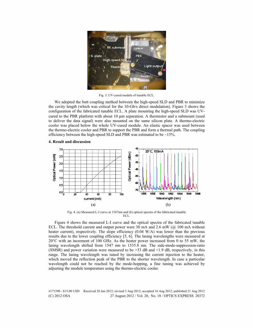
Fig. 3. UV-cured module of tunable ECL.
We adopted the butt coupling method between the high-speed SLD and PBR to minimize the cavity length (which was critical for the 10-Gb/s direct modulation). Figure 3 shows the configuration of the fabricated tunable ECL. A plate mounting the high-speed SLD was UV-cured to the PBR platform with about 10 μm separation. A thermistor and a submount (used to deliver the data signal) were also mounted on the same silicon plate. A thermo-electric cooler was placed below the whole UV-cured module. An elastic spacer was used between the thermo-electric cooler and PBR to support the PBR and form a thermal path. The coupling efficiency between the high-speed SLD and PBR was estimated to be ~15%.
4. Result and discussion
Fig. 4. (a) Measured L-I curve at 1547nm and (b) optical spectra of the fabricated tunable ECL.
Figure 4 shows the measured L-I curve and the optical spectra of the fabricated tunable ECL. The threshold current and output power were 30 mA and 2.6 mW (@ 100 mA without heater current), respectively. The slope efficiency (0.04 W/A) was lower than the previous results due to the lower coupling efficiency [5, 6]. The lasing wavelengths were measured at 20°C with an increment of 100 GHz. As the heater power increased from 0 to 55 mW, the lasing wavelength shifted from 1547 nm to 1535.8 nm. The side-mode-suppression-ratio (SMSR) and power variation were measured to be >33 dB and <1.9 dB, respectively, in this range. The lasing wavelength was tuned by increasing the current injection to the heater, which moved the reflection peak of the PBR to the shorter wavelength. In case a particular wavelength could not be reached by the mode-hopping, a fine tuning was achieved by adjusting the module temperature using the thermo-electric cooler.
#171590 - $15.00 USD Received 28 Jun 2012; revised 3 Aug 2012; accepted 16 Aug 2012; published 21 Aug 2012(C) 2012 OSA 27 August 2012 / Vol. 20, No. 18 / OPTICS EXPRESS 20372

The fine tuning (obtained by using the thermo-electric cooler) could also be used for the detuned loading effect. Figure 5 shows the wavelength shifts measured by using the thermo-electric cooler which changes the temperature of the whole UV-cured module. As will be described later, two lasing modes were possible under the same operating condition. However, we could select one particular lasing wavelength by either increasing or decreasing the temperature of the UV-cured module. In this bistable region, the longer wavelength lasing can be achieved by increasing the module temperature although the static properties such as SMSR and lasing mode power are slightly degraded.
Fig. 5. Measured wavelength of the fabricated ECL as a function of the UV-module temperature.
Fig. 6. Bandwidths of the fabricated tunable ECL measured at three different wavelengths.
Figure 6 shows the modulation bandwidth of the fabricated ECL measured at three different wavelengths of 1547 nm (heater current 0 mA, module temperature 21.4°C), 1545 nm (13.7 mA, 21.4°C), and 1538 nm (27.85 mA, 20.2°C). All data show sufficient bandwidths for the 10-Gb/s operation although the detailed shapes are slightly different from each other due to different detuned loading conditions. Figure 7 shows the results of the bit-error ratio (BER) measurements under the same conditions. The tunable ECL was directly modulated at 9.953 Gb/s using a pseudo-random binary sequence with a pattern length of 231-1. The bias current and the peak-to-peak modulation voltage were set to be 100 mA and 2.8V, respectively. Under these conditions, the extinction ratios were measured to be in the range of
#171590 - $15.00 USD Received 28 Jun 2012; revised 3 Aug 2012; accepted 16 Aug 2012; published 21 Aug 2012(C) 2012 OSA 27 August 2012 / Vol. 20, No. 18 / OPTICS EXPRESS 20373
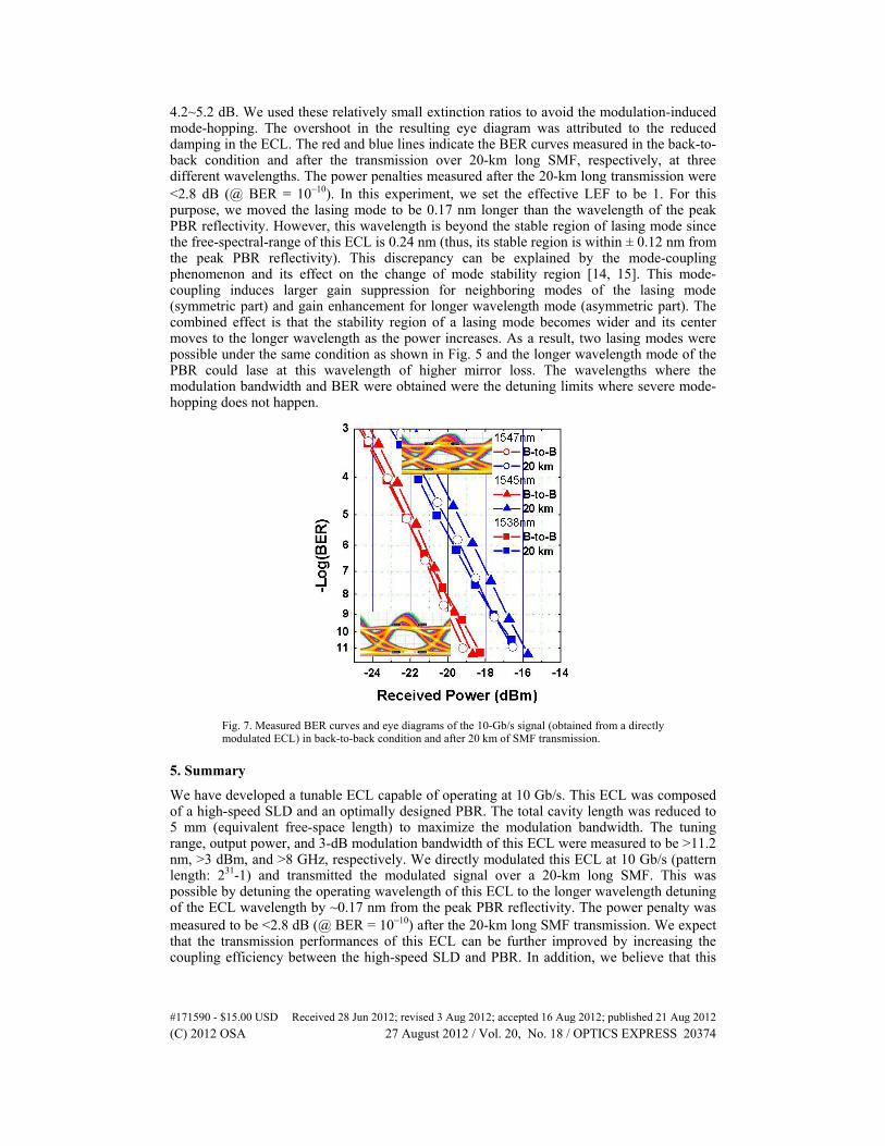
4.2~5.2 dB. We used these relatively small extinction ratios to avoid the modulation-induced mode-hopping. The overshoot in the resulting eye diagram was attributed to the reduced damping in the ECL. The red and blue lines indicate the BER curves measured in the back-to-back condition and after the transmission over 20-km long SMF, respectively, at three different wavelengths. The power penalties measured after the 20-km long transmission were <2.8 dB (@ BER = 10−10). In this experiment, we set the effective LEF to be 1. For this purpose, we moved the lasing mode to be 0.17 nm longer than the wavelength of the peak PBR reflectivity. However, this wavelength is beyond the stable region of lasing mode since the free-spectral-range of this ECL is 0.24 nm (thus, its stable region is within ± 0.12 nm from the peak PBR reflectivity). This discrepancy can be explained by the mode-coupling phenomenon and its effect on the change of mode stability region [14, 15]. This mode-coupling induces larger gain suppression for neighboring modes of the lasing mode (symmetric part) and gain enhancement for longer wavelength mode (asymmetric part). The combined effect is that the stability region of a lasing mode becomes wider and its center moves to the longer wavelength as the power increases. As a result, two lasing modes were possible under the same condition as shown in Fig. 5 and the longer wavelength mode of the PBR could lase at this wavelength of higher mirror loss. The wavelengths where the modulation bandwidth and BER were obtained were the detuning limits where severe mode-hopping does not happen.
Fig. 7. Measured BER curves and eye diagrams of the 10-Gb/s signal (obtained from a directly modulated ECL) in back-to-back condition and after 20 km of SMF transmission.
5. Summary
We have developed a tunable ECL capable of operating at 10 Gb/s. This ECL was composed of a high-speed SLD and an optimally designed PBR. The total cavity length was reduced to 5 mm (equivalent free-space length) to maximize the modulation bandwidth. The tuning range, output power, and 3-dB modulation bandwidth of this ECL were measured to be >11.2 nm, >3 dBm, and >8 GHz, respectively. We directly modulated this ECL at 10 Gb/s (pattern length: 231-1) and transmitted the modulated signal over a 20-km long SMF. This was possible by detuning the operating wavelength of this ECL to the longer wavelength detuning of the ECL wavelength by ~0.17 nm from the peak PBR reflectivity. The power penalty was measured to be <2.8 dB (@ BER = 10−10) after the 20-km long SMF transmission. We expect that the transmission performances of this ECL can be further improved by increasing the coupling efficiency between the high-speed SLD and PBR. In addition, we believe that this
#171590 - $15.00 USD Received 28 Jun 2012; revised 3 Aug 2012; accepted 16 Aug 2012; published 21 Aug 2012(C) 2012 OSA 27 August 2012 / Vol. 20, No. 18 / OPTICS EXPRESS 20374

ECL has a potential to be low cost and can be used as colorless light source in 10-Gb/s WDM-PON systems.
Acknowledgments
This work is supported by the IT R&D Program of MK/IIT (10039164), Rep. of Korea.
#171590 - $15.00 USD Received 28 Jun 2012; revised 3 Aug 2012; accepted 16 Aug 2012; published 21 Aug 2012(C) 2012 OSA 27 August 2012 / Vol. 20, No. 18 / OPTICS EXPRESS 20375


