1.0 Exercises - Forsiden - Universitetet i Oslo\Subsea\Dept\Production Performance...
12
G:\Subsea\Dept\Production Performance Services\Department\C - Flow Assurance CC\M - Ongoing Projects\MEK4450- Tine\2013\MEK4450_Exercises_2013.doc 1.0 Exercises 1.1 Screening calculation: temperature loss over a Subsea Process Station and the effect of pipe insulation. A rough estimation of how much the fluid temperature drops in the Subsea Separation Station has been performed. The calculations show that the water line temperature is way outside the hydrate formation area when in production even without insulation. The sea temperature is assumed to be 8 degrees and the input fluid temperature 54 degrees. As this is a screening calculation to reveal whether there is a potential challenge or not conservative estimates are used for all numbers. For the heat exchange the two equations that will be used is Where is total rate of heat exchanged is mass rate in kg/s≈50kg/s is specific heat capacity of water≈4200J/kgK is the unknown loss of temperature over the SSAO And Where is total rate of heat exchanged is W/m2K is total area that the heat exchanges with surroundings is difference in temperature between production fluid and surroundings The U value will probably be between 100 and 10 depending on insulation The Area: Assumptions: L≈100m U≈100 W/m2K (without insulation) U≈10 W/m2K (with insulation) A≈2·3.14·0.05m·100m≈30m2 ≈46°C Without insulation:
Transcript of 1.0 Exercises - Forsiden - Universitetet i Oslo\Subsea\Dept\Production Performance...
G:\Subsea\Dept\Production Performance Services\Department\C - Flow Assurance CC\M - Ongoing Projects\MEK4450-
Tine\2013\MEK4450_Exercises_2013.doc
1.0 Exercises
1.1 Screening calculation: temperature loss over a Subsea Process Station and the effect of pipe insulation.
A rough estimation of how much the fluid temperature drops in the Subsea Separation Station has been performed. The calculations show that the water line temperature is way outside the hydrate formation area when in production even without insulation. The sea temperature is assumed to be 8 degrees and the input fluid temperature 54 degrees. As this is a screening calculation to reveal whether there is a potential challenge or not conservative estimates are used for all numbers. For the heat exchange the two equations that will be used is
Where
is total rate of heat exchanged
is mass rate in kg/s≈50kg/s
is specific heat capacity of water≈4200J/kgK
is the unknown loss of temperature over the SSAO And
Where
is total rate of heat exchanged
is W/m2K
is total area that the heat exchanges with surroundings
is difference in temperature between production fluid and surroundings The U value will probably be between 100 and 10 depending on insulation The Area: Assumptions: L≈100m U≈100 W/m2K (without insulation) U≈10 W/m2K (with insulation) A≈2·3.14·0.05m·100m≈30m2
≈46°C Without insulation:

G:\Subsea\Dept\Production Performance Services\Department\C - Flow Assurance CC\M - Ongoing Projects\MEK4450-
Tine\2013\MEK4450_Exercises_2013.doc
With insulation:
Conclusion: In both cases the change in the process fluid temperature is less than one degree. Extra: Look at the different variables and figure out the significance of the mass rate, the specific heat capacity and the rate. What would be the difference with a gas instead of water? Assume is specific heat capacity of gas≈2200J/kgK
What is the U value needed to keep the gas warm over the process station?
G:\Subsea\Dept\Production Performance Services\Department\C - Flow Assurance CC\M - Ongoing Projects\MEK4450-
Tine\2013\MEK4450_Exercises_2013.doc
1.2 Heat losses over a long pipe section
1.2.1 Problem
Crude oil is flowing down a 50 km subsea pipeline of external diameter 40 cm at a mass flow rate of 100 kg/s. Given the sea water temperature, the pipeline U-value and the oil temperature at the pipeline inlet, calculate the oil temperature at the pipeline outlet.
1.2.2 Inputs and assumptions
The U-value is the overall heat transfer coefficient of the pipeline expressed in W/K.m2. In this
example a U-value of 3 will be considered, corresponding to a weakly insulated pipeline.
The sea temperature Tsea is 7°C, the oil inlet temperature is Tin=50°C.
The crude oil has a specific heat capacity of cp=2 kJ/kg.K
The pressure is assumed to stay constant along the pipe length.
1.2.3 Solution
We need to find the evolution of the oil temperature in the pipeline as a function of the distance x from the inlet. Let us consider a small element of the pipeline extending between x and x+dx. A balance must be achieved between the heat transferred to the surrounding environment per second Qsea and the heat lost by the fluid over this small element (per second), Qfluid. By definition,
and where is the surface of contact area between the pipe and the sea over the element of length dx. By equalizing these two terms and letting dx tend towards zero we obtain the following first order differential equation:
This can be further simplified by posing :
The solution is simply with the constant C being determined with the inlet condition:
yielding finally: .

G:\Subsea\Dept\Production Performance Services\Department\C - Flow Assurance CC\M - Ongoing Projects\MEK4450-
Tine\2013\MEK4450_Exercises_2013.doc
After 50km, the oil temperature will then be down to 23.75 °C.
1.2.4 Extra
Use the linear approach from the solution in 1.1. What is necessary to know to be able to use a linear approach?

G:\Subsea\Dept\Production Performance Services\Department\C - Flow Assurance CC\M - Ongoing Projects\MEK4450-
Tine\2013\MEK4450_Exercises_2013.doc
1.3 Calculations of effect on pressure when enclosed system is cooled
Premises:
During a shutdown the SPS will be isolated from the rest of the system by enclosing of inlet and outlet valve on the bypass module, the system shall be able to produce in bypass modus
The isolated volume is the volume between inlet valve through the SPS, to outlet valve on the bypass module
As water is incompressible the effect of cooling on pressure in enclosed liquid lines can be neglected
In the multiphase part of the SSAO the gas will contract during a cooldown from normal operational temperature of 60°C to ambient temperature of 4°C
The amount of gas present in the multiphase part of the system is relatively low (actual GLR 0.5-1)
Because it is the gas that is going to contract any movement between parts of system will be from liquid lines to multiphase lines, it is therefore no gas entrainment into liquid lines
The differential pressure over the enclosed valves has been estimated As this is a screening calculation to reveal whether there is a potential challenge or not, conservative estimates are used for all numbers. We will assume that the SPS is not depressurized as a conservative approach, and that the shut-in pressure on the station is equal to a typical operating pressure of 60bara. To approach the problem we assume that we can use Avogadro's law and add 100% uncertainty.
2
22
1
11
T
VP
T
VP
21 PPP
Where
1P is pressure in gas before cooling
2P is pressure in gas after cooling
21 PPP
1T is operational temperature in Kelvin (333K)
2T is temperature after cooling in Kelvin equal to ambient temperature (277K)
V is enclosed volume before and after cooling
21 VV = Total volume needed to flush SSAO = 18,23m³
Target of interest is the potential P over a valve Insertion of values gives:
barPK
KP 9.49
333
27712

G:\Subsea\Dept\Production Performance Services\Department\C - Flow Assurance CC\M - Ongoing Projects\MEK4450-
Tine\2013\MEK4450_Exercises_2013.doc
barbarbarP 1.109.4960 Adding 100% uncertainty gives 20.2bar Conclusion: In a shutdown situation the multiphase part of the system will be filled with MEG, which will modify the contraction of the gas. The differential pressure over the valve is therefore with a high probability less than 20bar. High pressure is defined as above 210bars, but 20 bars dP over a valve could set some constraints on type and size. Notice: Avogadro's law is an experimental gas law relating volume of a gas to the amount of substance of gas present. For a given mass of an ideal gas, the volume and amount (moles) of the gas are directly proportional of the temperature and pressures are constant.
G:\Subsea\Dept\Production Performance Services\Department\C - Flow Assurance CC\M - Ongoing Projects\MEK4450-
Tine\2013\MEK4450_Exercises_2013.doc
1.4 Head loss and pumping power requirement in a water pipe
1.4.1 Problem
Water at 10°C is flowing steadily in a pipe of internal diameter 20 cm at a mass flow rate of 30 kg/s. Determine the pressure drop, the head loss and the pumping power input for flow over a 500 meters section of the pipe.
1.4.2 Inputs and assumptions
At 10°C the water density and dynamic viscosity are kg/m3 and
N.s/m2 respectively.
The flow is considered to be incompressible and hydro dynamically fully-developed along the
whole pipe length.
The pipe is made of stainless steel with an absolute roughness of 0.002 mm.
1.4.3 Solution
First we need to calculate the average (or bulk) velocity and the Reynolds number to determine the flow regime:
where A is the pipe cross-sectional area and the mass flow rate. This gives at
10°C cm/s and which far above 4000. Therefore the flow is turbulent. We will now calculate the friction factor f for this flow.
The relative roughness of the pipe is According to the Moody
chart the pipe can be considered as hydro dynamically smooth and Prandtl’s universal law of friction for smooth pipes can be used:
Using an iterative scheme or an equation solver we obtain . Alternatively we could read this value directly from the Moody chart but with less precision. The pressure drop ΔP, head loss hL and the required power input are then:
Pa (0.19 bars)
m
W
Notice: The Reynolds number is defined as HbDURe . It is a dimensionless quantity that
gives a measure of the ratio of inertial forces to viscous forces. It is used to characterize different flow regimes, laminar flow occurs at low Reynolds numbers, where viscous forces

G:\Subsea\Dept\Production Performance Services\Department\C - Flow Assurance CC\M - Ongoing Projects\MEK4450-
Tine\2013\MEK4450_Exercises_2013.doc
are dominant, turbulent flow occurs at high Reynolds numbers and is dominated by inertial forces which tend to produce chaotic eddies, vortices and other flow instabilities.

G:\Subsea\Dept\Production Performance Services\Department\C - Flow Assurance CC\M - Ongoing Projects\MEK4450-
Tine\2013\MEK4450_Exercises_2013.doc
1.5 Wellhead pressure at shut-in conditions
1.5.1 Problem
A reservoir situated at a depth of 4.5 km below the sea bottom is filled with an ideal gas characterized by a molar mass of 14 g/mol. The reservoir conditions are 455 bars and 130°C. Assuming shut-in conditions (i.e., no flow from the reservoir to the wellhead) what is the pressure difference between the reservoir and the wellhead?
1.5.2 Inputs and assumptions
The temperature and gas composition are assumed to be constant at all points between the
reservoir and the wellhead.
The piping diameter is also assumed to be constant.
The pressure is varying linearly with height.
1.5.3 Solution
In the following we will assume that the reservoir is at and the wellhead at height
km. For an ideal gas the density is defined by
where M is the molar mass of the gas and R the universal gas constant. Let Pres and
Pwell be the pressures at the reservoir and wellhead, respectively. Then:
Since the pressure is varying linearly with height,
and:
bars
There is a (small) trap here: T needs to be expressed in Kelvin and M in kg/mol.
G:\Subsea\Dept\Production Performance Services\Department\C - Flow Assurance CC\M - Ongoing Projects\MEK4450-
Tine\2013\MEK4450_Exercises_2013.doc
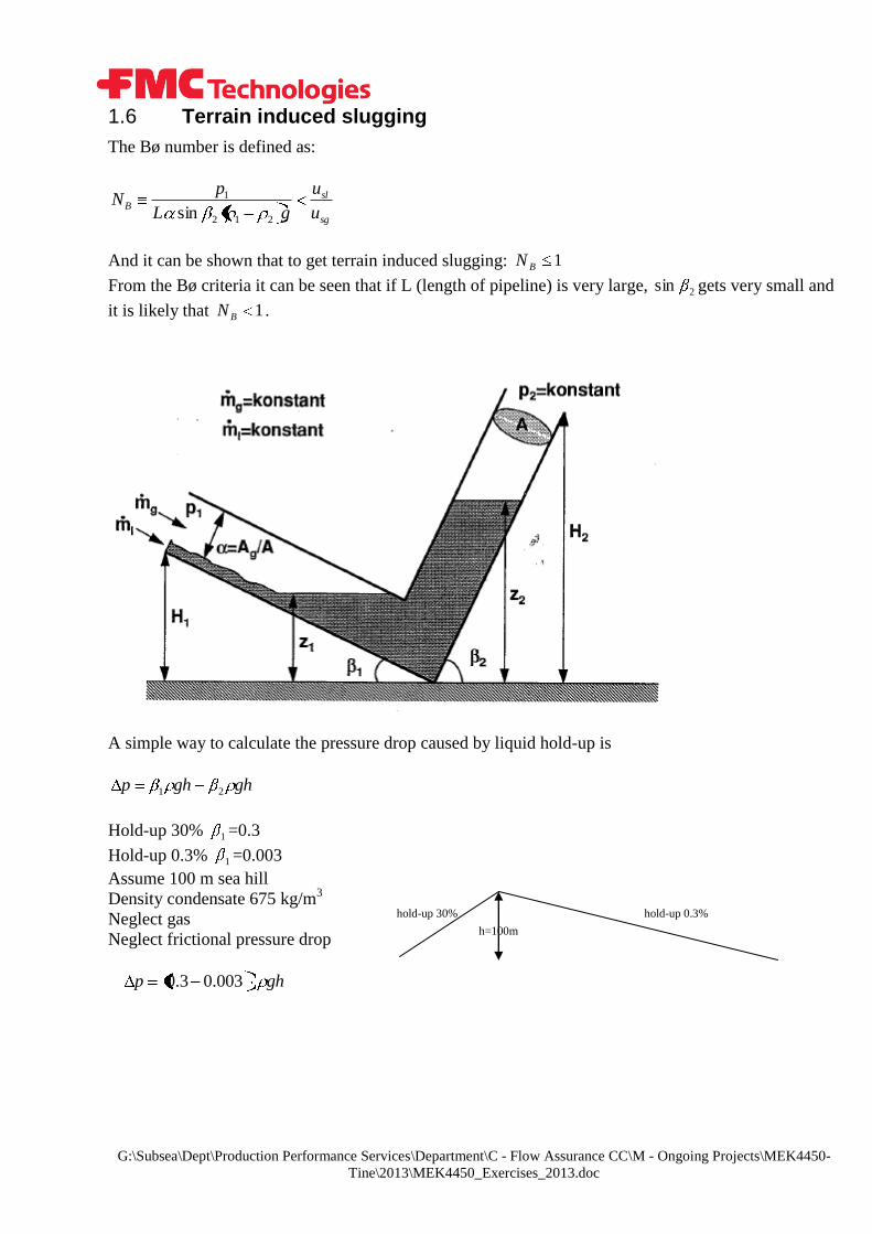
1.6 Terrain induced slugging
The Bø number is defined as:
sg
slB
u
u
gL
pN
212
1
sin
And it can be shown that to get terrain induced slugging: 1BN
From the Bø criteria it can be seen that if L (length of pipeline) is very large, 2sin gets very small and
it is likely that 1BN .
A simple way to calculate the pressure drop caused by liquid hold-up is
ghghp 21
Hold-up 30% 1 =0.3
Hold-up 0.3% 1 =0.003
Assume 100 m sea hill
Density condensate 675 kg/m3
Neglect gas
Neglect frictional pressure drop
ghp 003.03.0
hold-up 30% hold-up 0.3%
h=100m

G:\Subsea\Dept\Production Performance Services\Department\C - Flow Assurance CC\M - Ongoing Projects\MEK4450-
Tine\2013\MEK4450_Exercises_2013.doc
2.0 Attachments
2.1 Moody chart
G:\Subsea\Dept\Production Performance Services\Department\C - Flow Assurance CC\M - Ongoing Projects\MEK4450-
Tine\2013\MEK4450_Exercises_2013.doc
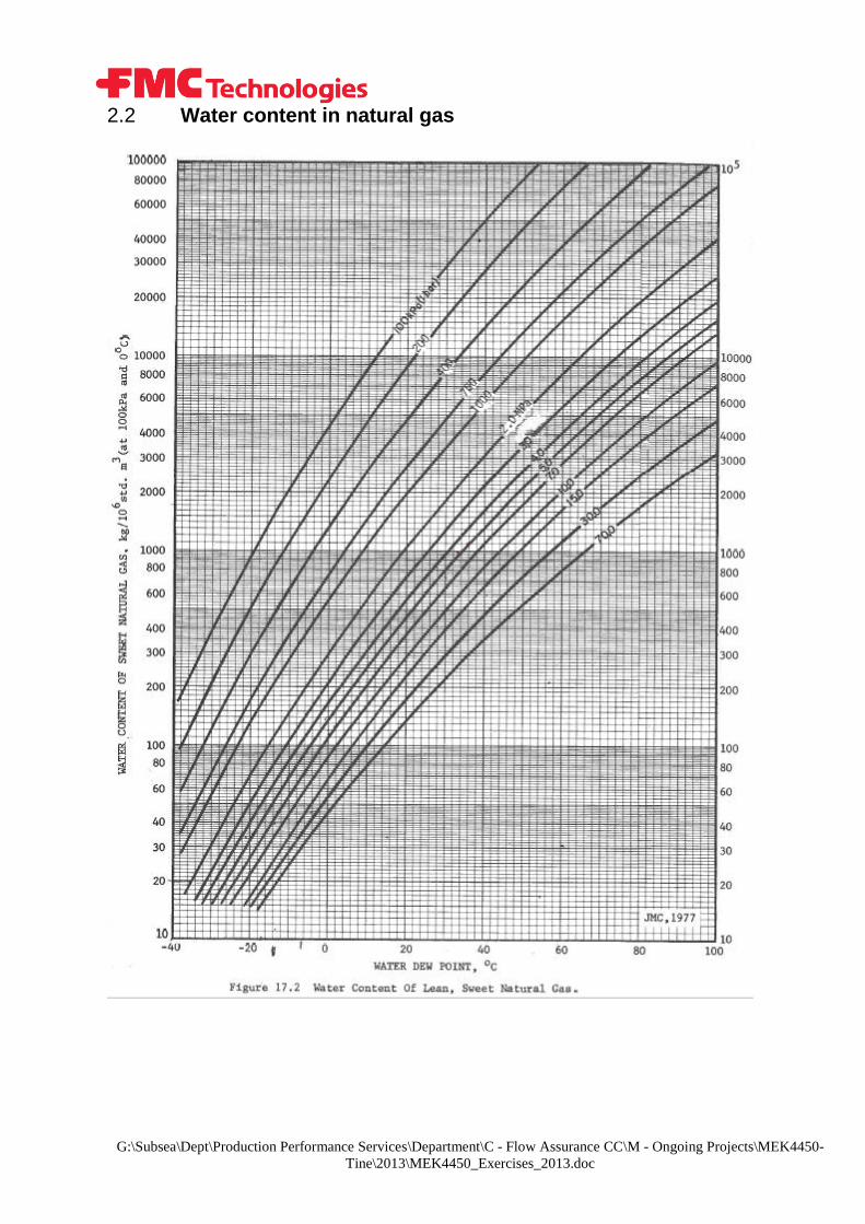
2.2 Water content in natural gas