10 days Retrofit to fix most problems! Shipyards 1 million employed 24/7! Yearly cost reduction 100...
69
1 © Wärtsilä 19 September 2008 Energy Efficiency Catalogue / Ship Power R&D BOOSTING ENERGY EFFICIENCY
-
Upload
wwwthiiinkcom -
Category
Environment
-
view
803 -
download
0
Transcript of 10 days Retrofit to fix most problems! Shipyards 1 million employed 24/7! Yearly cost reduction 100...
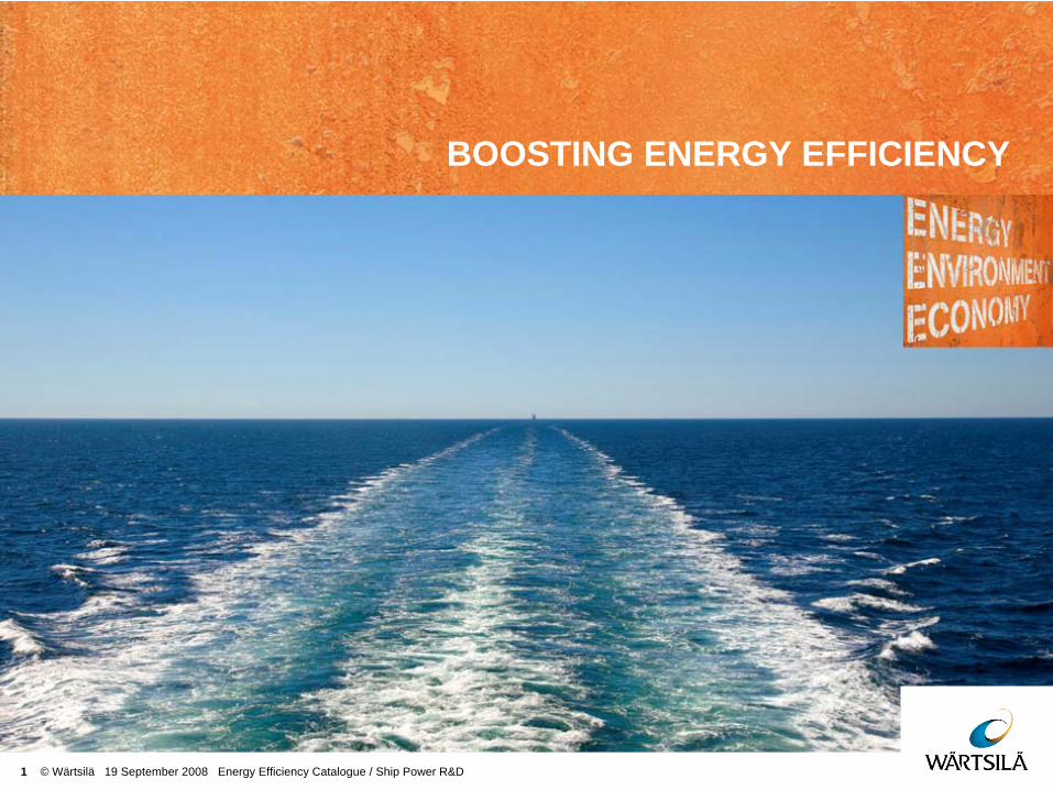
1 © Wärtsilä 19 September 2008 Energy Efficiency Catalogue / Ship Power R&D
BOOSTING ENERGY EFFICIENCY
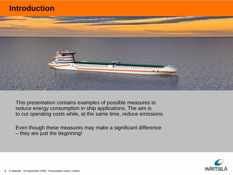
Introduction
2 © Wärtsilä 19 September 2008 Presentation name / Author
This presentation contains examples of possible measures to reduce energy consumption in ship applications. The aim is to cut operating costs while, at the same time, reduce emissions.
Even though these measures may make a significant difference – they are just the beginning!

Introduction
3 © Wärtsilä 19 September 2008 Presentation name / Author
Our aim is to show from a neutral viewpoint a vast range of potential areas for efficiency improvement. They are based on today’s technology and are presented irrespective of the present availability of such solutions either from Wärtsilä or any other supplier.
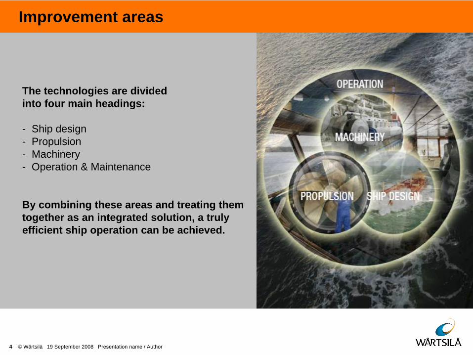
Improvement areas
4 © Wärtsilä 19 September 2008 Presentation name / Author
The technologies are divided into four main headings:
- Ship design - Propulsion - Machinery - Operation & Maintenance
By combining these areas and treating them together as an integrated solution, a truly efficient ship operation can be achieved.

MORE INFO
BACK
Symbol explanations
5 © Wärtsilä 19 September 2008 Presentation name / Author
< 4%
Ship types for which the energy efficiency improvement measure is well suited.
Energy consumption reduction method applicability:
Measures that can be retrofitted to an existing vessel
Operational measures
Methods best suited for new buildings
Payback time indication:
Short (<1 year) – Long (>15 years)
An upper percentage of the potential annual saving in fuel consumption for the entire ship, not looking just at the saving in one mode for a specific part of the power demand.

TANKERS AND BULKERS
6 © Wärtsilä 19 September 2008 Presentation name / Author
AIR LUBRICATIONAIR LUBRICATION
DELTA TUNINGDELTA TUNING
OPTIMUM MAIN DIMENSIONS OPTIMUM MAIN DIMENSIONS
ENERGOPACENERGOPAC
HULL CLEANINGHULL CLEANINGWIND POWERWIND POWER
VOYAGER PLANNING – WEATHER ROUTING VOYAGER PLANNING – WEATHER ROUTING

CONTAINER VESSELS
7 © Wärtsilä 19 September 2008 Presentation name / Author
LIGHTWEIGHT CONSTRUCTION LIGHTWEIGHT CONSTRUCTION
PROPELLER BLADE DESIGN PROPELLER BLADE DESIGN
HULL SURFACE – HULL COATING HULL SURFACE – HULL COATING
BOW THRUSTER SCALLOPS / GRIDS BOW THRUSTER SCALLOPS / GRIDS
WASTE HEAT RECOVERY WASTE HEAT RECOVERY
AUTOPILOT ADJUSTMENTS AUTOPILOT ADJUSTMENTS
SHIP SPEED REDUCTION SHIP SPEED REDUCTION
EFFICIENCY OF SCALE EFFICIENCY OF SCALE
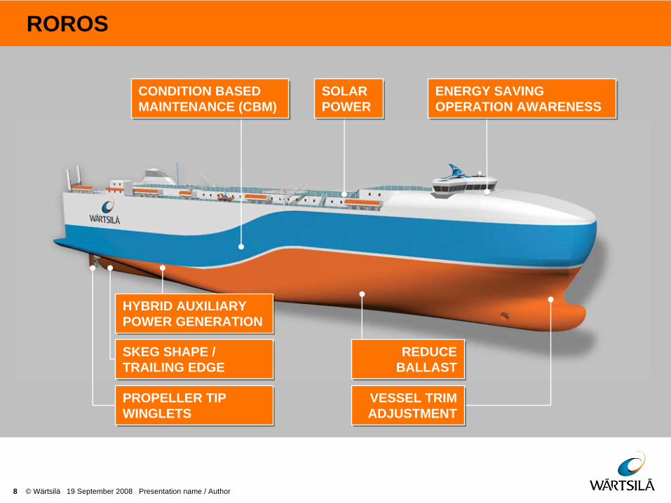
ROROS
8 © Wärtsilä 19 September 2008 Presentation name / Author
HYBRID AUXILIARY POWER GENERATION HYBRID AUXILIARY POWER GENERATION
SKEG SHAPE / TRAILING EDGE SKEG SHAPE / TRAILING EDGE
PROPELLER TIP WINGLETS PROPELLER TIP WINGLETS
CONDITION BASED MAINTENANCE (CBM) CONDITION BASED MAINTENANCE (CBM)
SOLAR POWER SOLAR POWER
ENERGY SAVING OPERATION AWARENESS ENERGY SAVING OPERATION AWARENESS
REDUCE BALLAST REDUCE
BALLAST
VESSEL TRIM ADJUSTMENT VESSEL TRIM ADJUSTMENT

FERRIES
9 © Wärtsilä 19 September 2008 Presentation name / Author
ENERGY SAVING LIGHTNING ENERGY SAVING LIGHTNING
LIGHTWEIGHT CONSTRUCTION LIGHTWEIGHT CONSTRUCTION
PROPULSION CONCEPTS – CRP PROPULSION CONCEPTS – CRP
CODED MACHINERY CODED MACHINERY
FUEL TYPE – LNG FUEL TYPE – LNG
TURNAROUND TIME IN PORT TURNAROUND TIME IN PORT
INTERCEPTOR TRIM PLANES INTERCEPTOR TRIM PLANES
COOLING WATER PUMPS, SPEED CONTROL COOLING WATER PUMPS, SPEED CONTROL

OFFSHORE SUPPORT VESSELS
10 © Wärtsilä 19 September 2008 Presentation name / Author
LOW LOSS CONCEPT FOR ELECTRIC NETWORK LOW LOSS CONCEPT FOR ELECTRIC NETWORK
PROPELLER NOZZLE PROPELLER NOZZLE
PROPELLER HULL INTERACTION OPTIMIZATION PROPELLER HULL INTERACTION OPTIMIZATION
RECTACTABLE THRUSTERS RECTACTABLE THRUSTERS
COMMON RAIL COMMON RAIL
POWER MANAGEMENT POWER MANAGEMENT
CODED MACHINERY CODED MACHINERY

11 © Wärtsilä 19 September 2008 Presentation name / Author
SHIP DESIGN
MORE INFO
BACK
12 © Wärtsilä 19 September 2008 Presentation name / Author
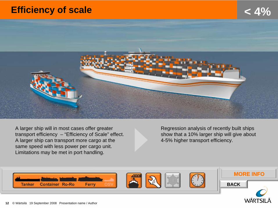
Efficiency of scale
A larger ship will in most cases offer greater transport efficiency – “Efficiency of Scale” effect. A larger ship can transport more cargo at the same speed with less power per cargo unit. Limitations may be met in port handling.
MORE INFO
Regression analysis of recently built ships show that a 10% larger ship will give about 4-5% higher transport efficiency.
< 4%

MORE INFO
BACK
Reduce ballast
Minimising the use of ballast (and other unnecessary weight) results in lighter displacement and thus lower resistance. The resistance is more or less directly proportional to displacement of the vessel. However there is need to have enough ballast in order to immerse the propeller in the water, sufficient stability (safety) and acceptable sea keeping behaviour (slamming).
13 © Wärtsilä 19 September 2008 Presentation name / Author
< 7%
Removing 3000 ton of permanent ballast from a PCTC and instead achieving the same stability by increasing the beam 0.25 m will reduce propulsion power demand by 8,5%.

MORE INFO
BACK
Lightweight construction
14 © Wärtsilä 19 September 2008 Presentation name / Author
< 7%
Use of lightweight structures can reduce the ship weight. In structures that are not contributing to ship global strength use of aluminium or some other lightweight structure may be an interesting solution. Also the weight of steel structure can be reduced. In a conventional ship, the steel weight can be lowered by 5-20%, depending on the amount of high tensile steel already in use.
A 20% reduction in steel weight will give ~9% reduction in propulsion power. However, a 5% saving is more realistic, as high tensil steel is already used to some extent in many cases.

MORE INFO
BACK
Optimum main dimensions
15 © Wärtsilä 19 September 2008 Presentation name / Author
< 9%
Finding the optimum length and hull fullness ratio (Cb) has a big impact on the ship resistance.Large L/B ratio means that the ship will have smooth lines and low wave making resistance. On the other hand increasing length means increased wetted surface, which can have negative effect on total resistance. A too high block coefficient (Cb) makes hull lines too blunt and leads to increased resistance.
Adding 10-15% extra length to a typical product tanker can reduce the power demand by more than 10%.

MORE INFO
BACK
Interceptor trim planes
16 © Wärtsilä 19 September 2008 Presentation name / Author
< 4%
The Interceptor is a metal plate that is fitted vertically to the transom of a ship, covering the main breadth of the transom. This plate bends the flow over aft-body of the ship downwards creating a similar lift effect as a conventional trim wedge due to high pressure area behind the propellers. Interceptor is proved to be better than conventional trim wedge in some cases, but so far it’s used only in cruise vessels and RoRos. Interceptor is cheaper than a trim wedge as a retrofit.
1-5% lower propulsion power demand. Corresponding improvement up to < 4% in total energy demand for a typical ferry.

MORE INFO
BACK
Ducktail waterline extension
17 © Wärtsilä 19 September 2008 Presentation name / Author
< 7%
Ducktail is basically a lengthening of the aft ship. It is usually 3-6 meters long. Its basic idea is to lengthen the effective waterline and make the wetted transom smaller. This has positive effect on the resistance of the ship. In some cases best results are achieved when ducktale is used together with Interceptor.
4-10% lower propulsion power demand. Corresponding improvement 3-7% in total energy consumption for a typical ferry.
MORE INFO
BACK
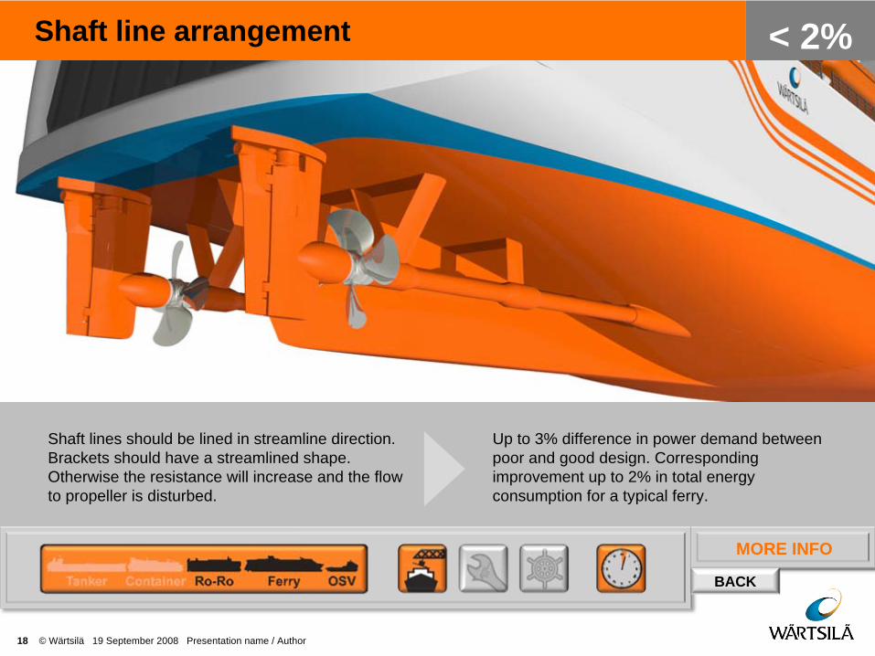
Shaft line arrangement
18 © Wärtsilä 19 September 2008 Presentation name / Author
< 2%
Shaft lines should be lined in streamline direction. Brackets should have a streamlined shape. Otherwise the resistance will increase and the flow to propeller is disturbed.
Up to 3% difference in power demand between poor and good design. Corresponding improvement up to 2% in total energy consumption for a typical ferry.

MORE INFO
BACK
Skeg shape / trailing edge
19 © Wärtsilä 19 September 2008 Presentation name / Author
< 2%
The skeg should be designed to direct the flow evenly to the propeller disk. At lower speeds it is typically beneficial to have more volume on the lower part of the skeg and as thin as possible above the propeller shaftline. At the aft end of the skeg the flow should be attached to skeg, but with as low flow speeds as possible.
1.5%-2% lower propulsion power demand with good design. Corresponding improvement up to 2% in total energy consumption for container vessel.

MORE INFO
BACK
Minimising resistance of hull openings
20 © Wärtsilä 19 September 2008 Presentation name / Author
< 5%
The water flow disturbance from openings to bow thruster tunnels and sea chests can be high. It is therefore beneficial to install scallop behind each opening. Alternatively a grid that is perpendicular to the local flow direction can be installed. The location of the opening is also important.
Good design of all openings combined with proper location can give up to 5% lower power demand than with poor designs. For container vessel corresponding improvement in total energy consumption is almost 5%.
MORE INFO
BACK
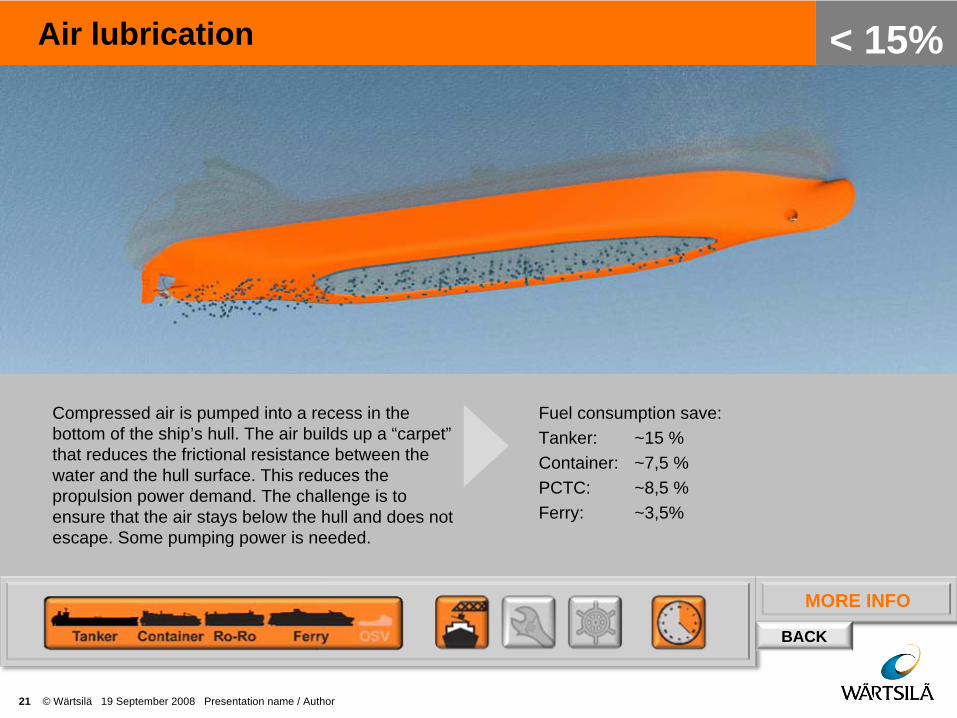
Air lubrication
21 © Wärtsilä 19 September 2008 Presentation name / Author
< 15%
Compressed air is pumped into a recess in the bottom of the ship’s hull. The air builds up a “carpet” that reduces the frictional resistance between the water and the hull surface. This reduces the propulsion power demand. The challenge is to ensure that the air stays below the hull and does not escape. Some pumping power is needed.
Fuel consumption save:Tanker: ~15 % Container: ~7,5 % PCTC: ~8,5 % Ferry: ~3,5%
MORE INFO
BACK
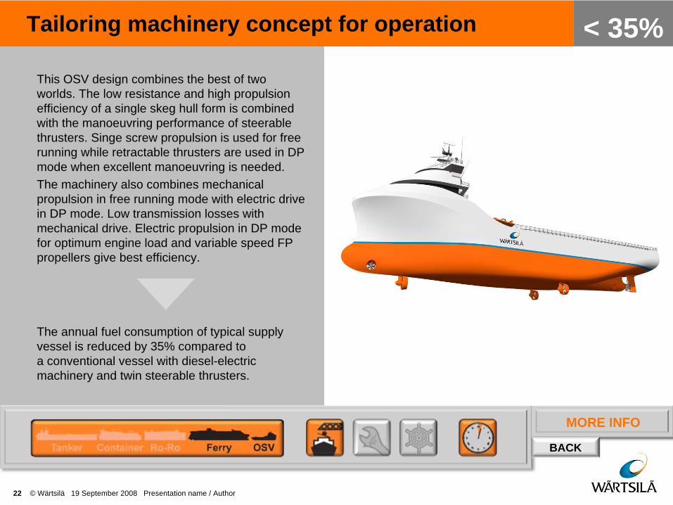
Tailoring machinery concept for operation
22 © Wärtsilä 19 September 2008 Presentation name / Author
< 35%This OSV design combines the best of two worlds. The low resistance and high propulsion efficiency of a single skeg hull form is combined with the manoeuvring performance of steerable thrusters. Singe screw propulsion is used for free running while retractable thrusters are used in DP mode when excellent manoeuvring is needed.The machinery also combines mechanical propulsion in free running mode with electric drive in DP mode. Low transmission losses with mechanical drive. Electric propulsion in DP mode for optimum engine load and variable speed FP propellers give best efficiency.
The annual fuel consumption of typical supply vessel is reduced by 35% compared to a conventional vessel with diesel-electric machinery and twin steerable thrusters.

23 © Wärtsilä 19 September 2008 Presentation name / Author
PROPULSION
MORE INFO
BACK
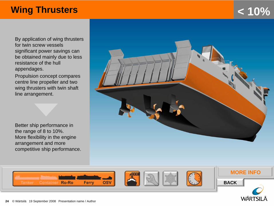
Wing Thrusters
24 © Wärtsilä 19 September 2008 Presentation name / Author
< 10%
By application of wing thrusters for twin screw vessels significant power savings can be obtained mainly due to less resistance of the hull appendages.Propulsion concept compares centre line propeller and two wing thrusters with twin shaft line arrangement.
Better ship performance in the range of 8 to 10%. More flexibility in the engine arrangement and more competitive ship performance.
MORE INFO
BACK
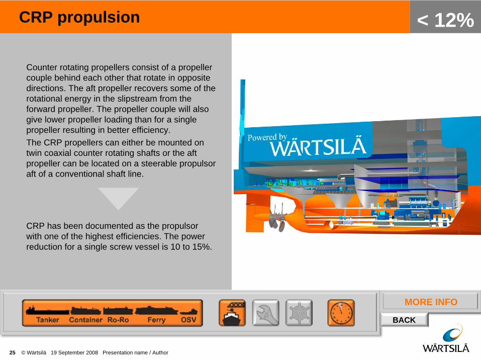
CRP propulsion
25 © Wärtsilä 19 September 2008 Presentation name / Author
< 12%
Counter rotating propellers consist of a propeller couple behind each other that rotate in opposite directions. The aft propeller recovers some of the rotational energy in the slipstream from the forward propeller. The propeller couple will also give lower propeller loading than for a single propeller resulting in better efficiency. The CRP propellers can either be mounted on twin coaxial counter rotating shafts or the aft propeller can be located on a steerable propulsor aft of a conventional shaft line.
CRP has been documented as the propulsor with one of the highest efficiencies. The power reduction for a single screw vessel is 10 to 15%.
MORE INFO
BACK
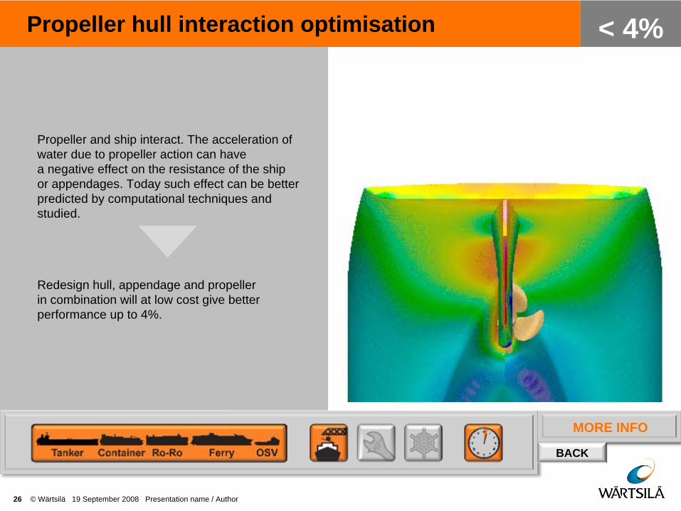
Propeller hull interaction optimisation
26 © Wärtsilä 19 September 2008 Presentation name / Author
< 4%
Propeller and ship interact. The acceleration of water due to propeller action can have a negative effect on the resistance of the ship or appendages. Today such effect can be better predicted by computational techniques and studied.
Redesign hull, appendage and propeller in combination will at low cost give better performance up to 4%.

MORE INFO
BACK
Propeller-rudder combinations
27 © Wärtsilä 19 September 2008 Presentation name / Author
< 4%
The rudder has drag in the order of 5% of ship resistance. This can be reduced by 50% by changing rudder profile and propeller. Designing in combination with a rudder bulb will give additional benefits. This system is called Energopac (R) system.
Improved fuel efficiency by 2 to 6%.

MORE INFO
BACK
Advanced propeller blade sections
28 © Wärtsilä 19 September 2008 Presentation name / Author
< 2%
Advanced blade sections will improve cavitation performance and frictional resistance of a propeller blade. As a result the propeller is more efficient.
Improved propeller efficiency up to 2%.

MORE INFO
BACK
Propeller tip winglets
29 © Wärtsilä 19 September 2008 Presentation name / Author
< 4%
Winglets are know from the aircraft industry. Application of special tip shapes can now be based on computational fluid dynamic calculations which will improve propeller efficiency.
Improved propeller efficiency up to 4%.
MORE INFO
BACK
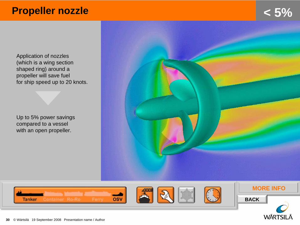
Propeller nozzle
30 © Wärtsilä 19 September 2008 Presentation name / Author
< 5%
Application of nozzles (which is a wing section shaped ring) around a propeller will save fuel for ship speed up to 20 knots.
Up to 5% power savings compared to a vessel with an open propeller.

MORE INFO
BACK
Constant versus variable speed operation
31 © Wärtsilä 19 September 2008 Presentation name / Author
< 5%
For controllable pitch propellers operation at constant number of revolutions over a wide ship speed reduces efficiency. Reduction of the number of revolutions at reduced ship speed will give fuel saving.
Save 5% fuel, depending on actual operating conditions.

MORE INFO
BACK
Wind power – sails and kites
32 © Wärtsilä 19 September 2008 Presentation name / Author
< 20%
Wing shaped sails installed on the deck or a kite attached to the bow of the ship uses the wind energy for added forward thrust. Both static wings with composite material and fabric material are possible.
Fuel consumption savings:Tanker ~ 21%PCTC ~20%Ferry ~8,5%

MORE INFO
BACK
Wind power – Flettner rotor
33 © Wärtsilä 19 September 2008 Presentation name / Author
< 30%
Spinning vertical rotors installed on the ship converts wind power according to the Magnus effect into thrust in the perpendicular direction of the wind. This means that in side wind conditions the ship will benefit from the added thrust.
Less propulsion power is required and hence a reduced fuel consumption.
MORE INFO
BACK
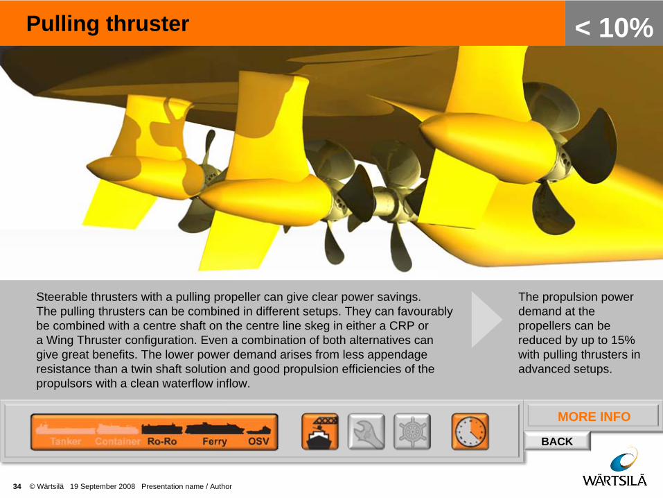
Pulling thruster
34 © Wärtsilä 19 September 2008 Presentation name / Author
< 10%
Steerable thrusters with a pulling propeller can give clear power savings. The pulling thrusters can be combined in different setups. They can favourably be combined with a centre shaft on the centre line skeg in either a CRP or a Wing Thruster configuration. Even a combination of both alternatives can give great benefits. The lower power demand arises from less appendage resistance than a twin shaft solution and good propulsion efficiencies of the propulsors with a clean waterflow inflow.
The propulsion power demand at the propellers can be reduced by up to 15% with pulling thrusters in advanced setups.

MORE INFO
BACK
Propeller efficiency measurement
35 © Wärtsilä 19 September 2008 Presentation name / Author
< 2%
Measure performance data on board to save fuel.Data will contain propeller performance data such as speed through the water, propeller torque and propeller thrust.
Accurate measurement of propeller data will enable fuel savings in operation. Experience shows that reduces fuel as much as 4%.

36 © Wärtsilä 19 September 2008 Presentation name / Author
MACHINERY
MORE INFO
BACK
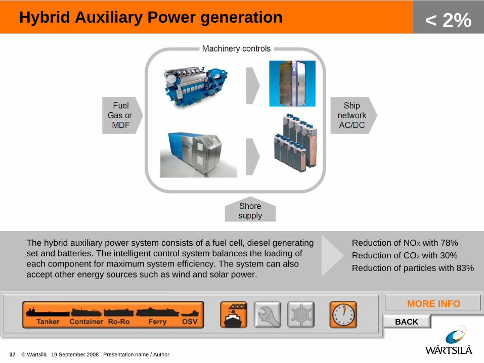
Hybrid Auxiliary Power generation
37 © Wärtsilä 19 September 2008 Presentation name / Author
< 2%
The hybrid auxiliary power system consists of a fuel cell, diesel generating set and batteries. The intelligent control system balances the loading of each component for maximum system efficiency. The system can also accept other energy sources such as wind and solar power.
Reduction of NOX with 78%Reduction of CO2 with 30%Reduction of particles with 83%

MORE INFO
BACK
Diesel electric machinery
38 © Wärtsilä 19 September 2008 Presentation name / Author
< 20%
Application of electric drives will be more effective in operation especially where change in operation and load profiles are a part of normal operation. Other important areas are processes where speed regulation can be utilised. Installation of electric propulsion gives following main benefits: - reduced installed power (typical >10%)- flexible arrangement (more cargo area)- flexible and efficient operation- excellent redundancy
The savings can be as much as 20-30% fuel reduction when DP is a part of the operation.For other vessel operational profiles fuel savings can typically be between 5-8%.

MORE INFO
BACK
CODED machinery
39 © Wärtsilä 19 September 2008 Presentation name / Author
< 4%Combined Diesel-Electric and Diesel-Mechanical machinery can improve the total efficiency in ships with an operational profile containing modes with varying loads. The electric power plant part will bring benefits at part load, were the engine load is optimised by selecting the right number of engines in use. At higher loads, the mechanical part will offer lower transmission losses than a fully electric machinery.
Total energy consumption for a offshore support vessel with CODED machinery is reduced by 4% compared to a diesel- electric machinery.
MORE INFO
BACK
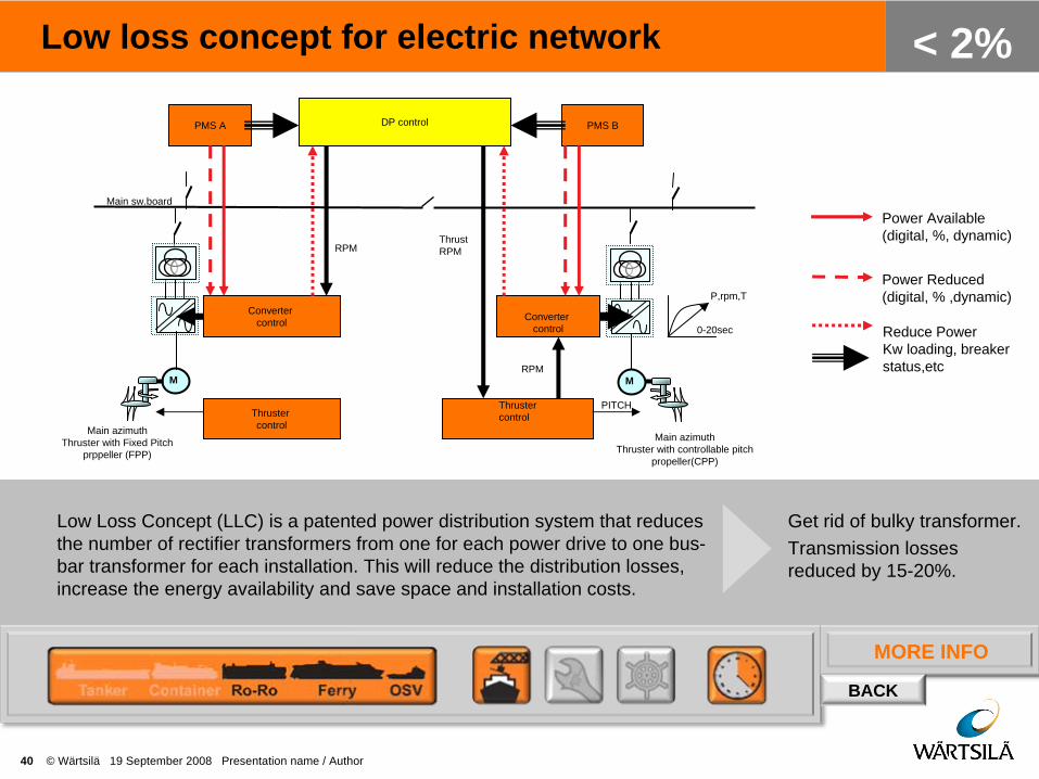
Low loss concept for electric network
40 © Wärtsilä 19 September 2008 Presentation name / Author
< 2%
Low Loss Concept (LLC) is a patented power distribution system that reduces the number of rectifier transformers from one for each power drive to one bus- bar transformer for each installation. This will reduce the distribution losses, increase the energy availability and save space and installation costs.
Get rid of bulky transformer.Transmission losses reduced by 15-20%.
Power Available (digital, %, dynamic)
Power Reduced (digital, % ,dynamic)
Reduce Power Kw loading, breaker status,etc
M M
Main sw.board
Main azimuthThruster with Fixed Pitch
prppeller (FPP)
Main azimuthThruster with controllable pitch
propeller(CPP)
PMS A PMS B
Converter control Converter
control
Thrustercontrol
Thrustercontrol
DP control
RPM
PITCH
ThrustRPM
RPM
P,rpm,T
0-20sec

MORE INFO
BACK
Variable speed electric power generation
41 © Wärtsilä 19 September 2008 Presentation name / Author
< 3%
The system uses generating sets operating in a variable rpm mode. The rpm is always adjusted for maximum efficiency regardless of the system load. The electrical system is based on DC distribution and frequency controlled consumers.
Reduce number of generating sets 25%.Optimised fuel consumption 5-10%.
MORE INFO
BACK
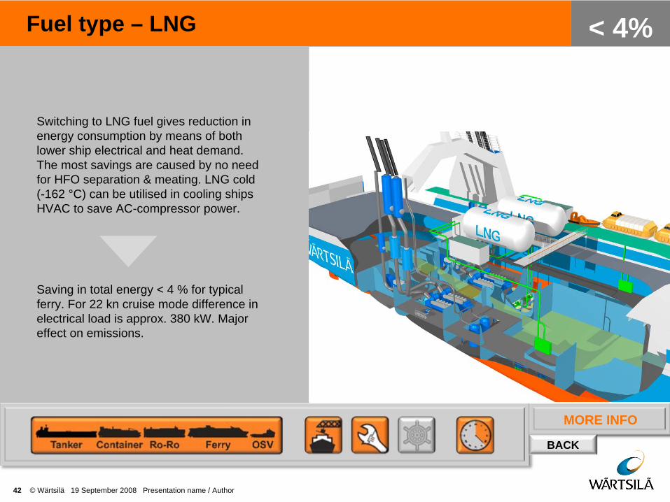
Fuel type – LNG
42 © Wärtsilä 19 September 2008 Presentation name / Author
< 4%
Switching to LNG fuel gives reduction in energy consumption by means of both lower ship electrical and heat demand. The most savings are caused by no need for HFO separation & meating. LNG cold (-162 °C) can be utilised in cooling ships HVAC to save AC-compressor power.
Saving in total energy < 4 % for typical ferry. For 22 kn cruise mode difference in electrical load is approx. 380 kW. Major effect on emissions.

MORE INFO
BACK
Waste heat recovery
43 © Wärtsilä 19 September 2008 Presentation name / Author
< 10%
Waste heat recovery (WHR) recovers the thermal exhaust gas energy converting it into electrical energy. Residual heat can further be used for ship onboard services. The system can consist of a boiler, a power turbine and a steam turbine with alternator. A redesign of the ship arrangement can efficiently accommodate the boilers in the ship.
Exhaust waste heat recovery can provide up to 15% of the engine power. Potential with new designs is up to 20%.
MORE INFO
BACK
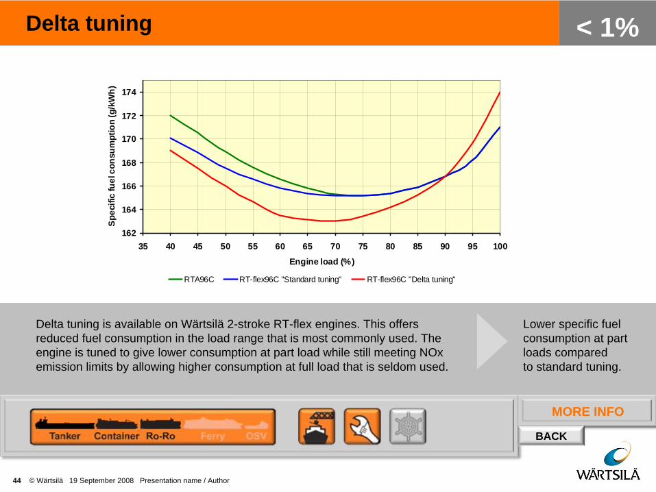
Delta tuning
44 © Wärtsilä 19 September 2008 Presentation name / Author
< 1%
162
164
166
168
170
172
174
35 40 45 50 55 60 65 70 75 80 85 90 95 100
Engine load (%)
Spe
cific
fuel
con
sum
ptio
n (g
/kW
h)
RTA96C RT-flex96C "Standard tuning" RT-flex96C "Delta tuning"
Delta tuning is available on Wärtsilä 2-stroke RT-flex engines. This offers reduced fuel consumption in the load range that is most commonly used. The engine is tuned to give lower consumption at part load while still meeting NOx emission limits by allowing higher consumption at full load that is seldom used.
Lower specific fuel consumption at part loads compared to standard tuning.

MORE INFO
BACK
Common rail
45 © Wärtsilä 19 September 2008 Presentation name / Author
< 1%
CR is a tool to achieve low emissions and low SFOC. CR controls combustion so it can be optimised throughout the whole operation field to achieve at every load the lowest possible fuel consumption.
Smokeless operation at all loadsPart load impactFull load impact
MORE INFO
BACK
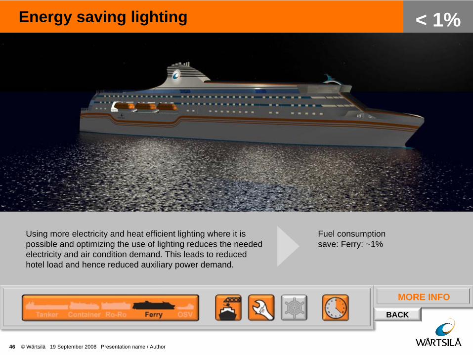
Energy saving lighting
46 © Wärtsilä 19 September 2008 Presentation name / Author
< 1%
Using more electricity and heat efficient lighting where it is possible and optimizing the use of lighting reduces the needed electricity and air condition demand. This leads to reduced hotel load and hence reduced auxiliary power demand.
Fuel consumption save: Ferry: ~1%

MORE INFO
BACK
Power management
47 © Wärtsilä 19 September 2008 Presentation name / Author
< 5%
The right timing of changing the number of generating sets is critical for the fuel consumption in Diesel Electric and auxiliary power installations. An efficient Power Management system is the best way to improve the system performance.
Running extensively at low load sharing can easily increase the SFOC with 5-10%.Low load increases the risk for turbine fouling with further impact on the fuel consumption.
G G G G
Propulsion azimuth
M
Propulsion azimuth
MBow thr. 1
M
Bow thr. 2
M
LLC Unit LLC Unit
MORE INFO
BACK
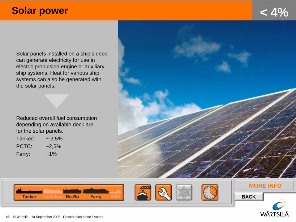
Solar power
48 © Wärtsilä 19 September 2008 Presentation name / Author
< 4%
Solar panels installed on a ship’s deck can generate electricity for use in electric propulsion engine or auxiliary ship systems. Heat for various ship systems can also be generated with the solar panels.
Reduced overall fuel consumption depending on available deck are for the solar panels. Tanker: ~ 3,5%PCTC: ~2,5%Ferry: ~1%
MORE INFO
BACK
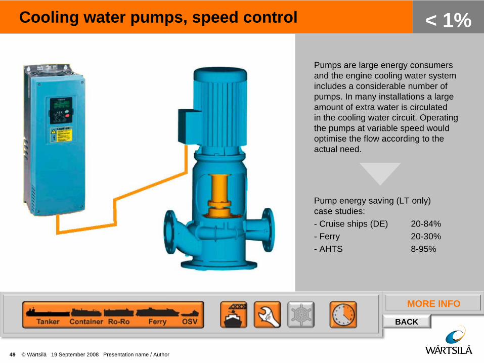
Cooling water pumps, speed control
49 © Wärtsilä 19 September 2008 Presentation name / Author
< 1%
Pumps are large energy consumers and the engine cooling water system includes a considerable number of pumps. In many installations a large amount of extra water is circulated in the cooling water circuit. Operating the pumps at variable speed would optimise the flow according to the actual need.
Pump energy saving (LT only) case studies:- Cruise ships (DE) 20-84%- Ferry 20-30%- AHTS 8-95%

MORE INFO
BACK
Automation
50 © Wärtsilä 19 September 2008 Presentation name / Author
< 10%Integrated Automation System (IAS) or Alarm and Monitoring System (AMS) includes functionality for advanced automatical monitoring and control of both efficiency and operational performance. The system integrates all vessel monitoring parameters and control all processes onboard to be able to operate the vessel at the lowest cost and best fuel performance.Power Drives distribute and regulate the optimum power needed for propeller thrust in any operational condition.
Engine optimisation control, power generation & distribution optimisation , thrust control and ballast optimisation save fuel consumption with 5-10%.

MORE INFO
BACK
Advanced power management
51 © Wärtsilä 19 September 2008 Presentation name / Author
< 5%
Power management based on intelligent control principles to monitor and control the overall efficiency and availability of the power system onboard. In efficiency mode the system will automatically run the system with the best energy cost.
Reduce the operational fuel cost and minimise maintenance by 5%.

52 © Wärtsilä 19 September 2008 Presentation name / Author
OPERATION & MAINTENANCE

MORE INFO
BACK
Fuel – additives
53 © Wärtsilä 19 September 2008 Presentation name / Author
< 2%
Keeping chargers and exhaust boilers clean means that engine efficiency can be maintained. Less soot in exhaust. Product to be used is Ferrocene which is organic iron based. Tested and used for many years in the car and shipping industry.
1-4 g/kWh reduction of SFOC as proven on 2-stroke installations.
MORE INFO
BACK
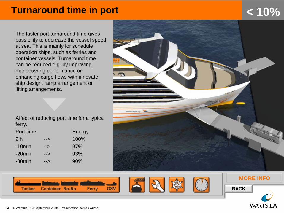
Turnaround time in port
54 © Wärtsilä 19 September 2008 Presentation name / Author
< 10%The faster port turnaround time gives possibility to decrease the vessel speed at sea. This is mainly for schedule operation ships, such as ferries and container vessels. Turnaround time can be reduced e.g. by improving manoeuvring performance or enhancing cargo flows with innovate ship design, ramp arrangement or lifting arrangements.
Affect of reducing port time for a typical ferry.Port time Energy2 h --> 100%-10min --> 97%-20min --> 93%-30min --> 90%
MORE INFO
BACK
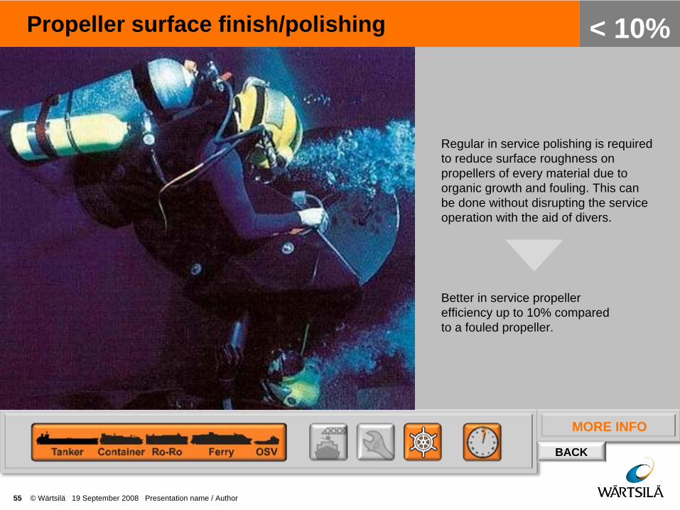
Propeller surface finish/polishing
55 © Wärtsilä 19 September 2008 Presentation name / Author
< 10%
Regular in service polishing is required to reduce surface roughness on propellers of every material due to organic growth and fouling. This can be done without disrupting the service operation with the aid of divers.
Better in service propeller efficiency up to 10% compared to a fouled propeller.
MORE INFO
BACK
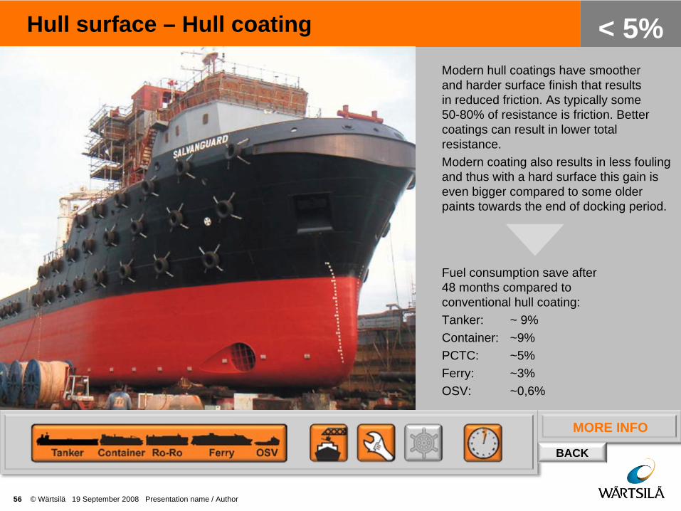
Hull surface – Hull coating
56 © Wärtsilä 19 September 2008 Presentation name / Author
< 5%Modern hull coatings have smoother and harder surface finish that results in reduced friction. As typically some 50-80% of resistance is friction. Better coatings can result in lower total resistance. Modern coating also results in less fouling and thus with a hard surface this gain is even bigger compared to some older paints towards the end of docking period.
Fuel consumption save after 48 months compared to conventional hull coating:Tanker: ~ 9%Container: ~9%PCTC: ~5%Ferry: ~3% OSV: ~0,6%

MORE INFO
BACK
Part load operation optimisation
57 © Wärtsilä 19 September 2008 Presentation name / Author
< 4%
Engines are usually optimised at high loads. In real life most of them are used on part loads. New matching taking in consideration real operation profiles can significantly improve overall operational efficiency.
New engine matching means different TC tuning, fuel injection advance, cam profiles, etc.

MORE INFO
BACK
Ship speed reduction
58 © Wärtsilä 19 September 2008 Presentation name / Author
< 23%
Ship speed reduction is efficient way to cut energy consumption. Propulsion power vs. ship speed is third power curve (according to theory) so significant reductions can be achieved. It should be noted that for lower speed the amount of transported cargo / time period is also lower. Calculated energy saving here is for equal distance travelled.
Ship speed reduction vs. saving in total energy consumption:- 0.5 kn --> - 7% energy- 1.0 kn --> - 11% energy- 2.0 kn --> - 17% energy- 3.0 kn --> - 23% energy
BACK

MORE INFO
BACK
Voyage planning – weather routing
59 © Wärtsilä 19 September 2008 Presentation name / Author
< 10%
The purpose of weather routing is to find the optimum solution for the long distance voyages where the shortest route is not always the fastest. The basic idea is to use updated weather forecast data and optimise the route via calm area or via areas which have most downwind tracks. Best systems also take into account currents trying to take as much benefit from those as possible. This track information can be imported to the navigation system.
Shorter passages, less fuel.

MORE INFO
BACK
Vessel trim
60 © Wärtsilä 19 September 2008 Presentation name / Author
< 5%
The optimum trim can often be as much as 15-20% lower than worst trim condition at same draught and speed. As the optimum trim is hull form dependent and for each hull form it depends on speed and draught, no general conclusions can be made. However by logging required power at various conditions over long time period it is possible to find optimum trim for each draught and speed. Or alternatively with CFD or model tests this can be fairly quickly determined. However it should be noted that correcting the trim by taking ballast will result in higher consumption (increased displacement). If possible the optimum trim should be achieved with either cargo positioning or if possible arranging bunkers differently.
Optimal vessel trim reduces required power.
MORE INFO
BACK
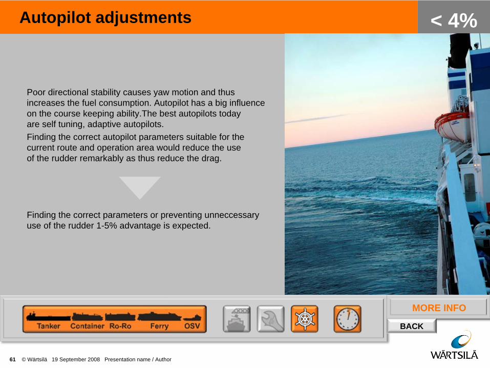
Autopilot adjustments
61 © Wärtsilä 19 September 2008 Presentation name / Author
< 4%
Poor directional stability causes yaw motion and thus increases the fuel consumption. Autopilot has a big influence on the course keeping ability.The best autopilots today are self tuning, adaptive autopilots. Finding the correct autopilot parameters suitable for the current route and operation area would reduce the use of the rudder remarkably as thus reduce the drag.
Finding the correct parameters or preventing unneccessary use of the rudder 1-5% advantage is expected.
MORE INFO
BACK
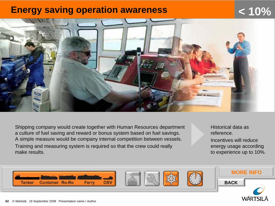
Energy saving operation awareness
62 © Wärtsilä 19 September 2008 Presentation name / Author
< 10%
Shipping company would create together with Human Resources department a culture of fuel saving and reward or bonus system based on fuel savings. A simple measure would be company internal competition between vessels.Training and measuring system is required so that the crew could really make results.
Historical data as reference.Incentives will reduce energy usage according to experience up to 10%.
MORE INFO
BACK
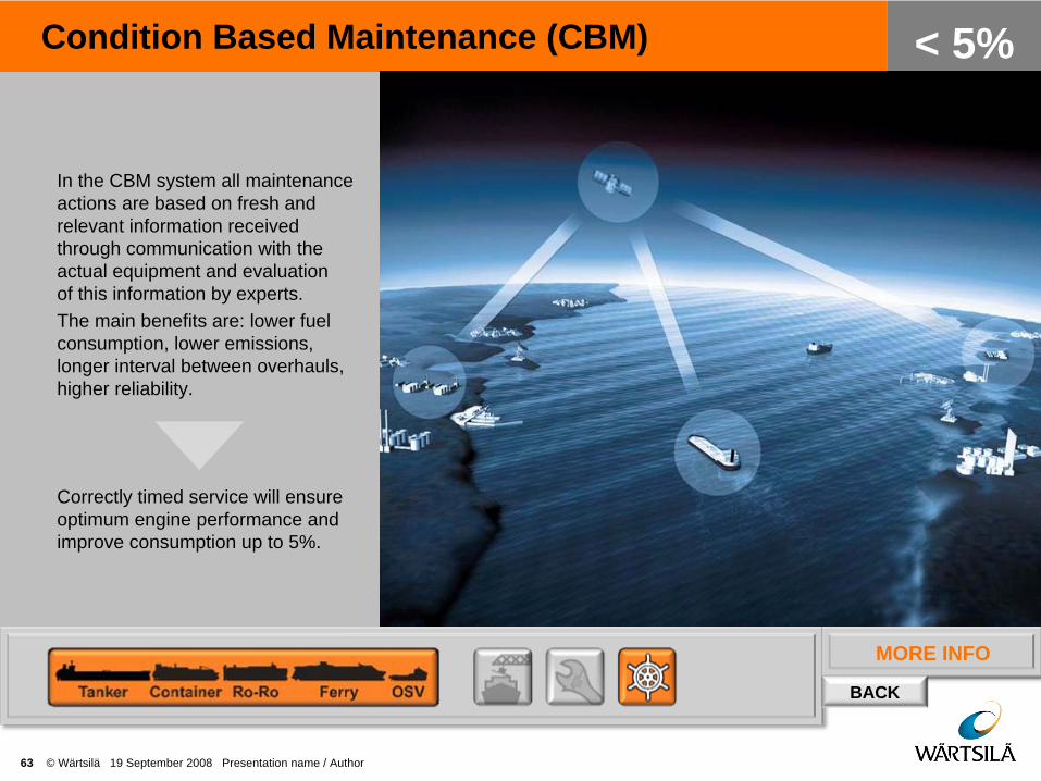
Condition Based Maintenance (CBM)
63 © Wärtsilä 19 September 2008 Presentation name / Author
< 5%
In the CBM system all maintenance actions are based on fresh and relevant information received through communication with the actual equipment and evaluation of this information by experts.The main benefits are: lower fuel consumption, lower emissions, longer interval between overhauls, higher reliability.
Correctly timed service will ensure optimum engine performance and improve consumption up to 5%.
MORE INFO
BACK
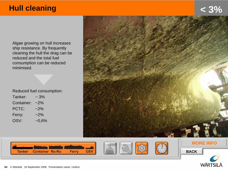
Hull cleaning
64 © Wärtsilä 19 September 2008 Presentation name / Author
< 3%
Algae growing on hull increases ship resistance. By frequently cleaning the hull the drag can be reduced and the total fuel consumption can be reduced minimised.
Reduced fuel consumption:Tanker: ~ 3%Container: ~2%PCTC: ~2%Ferry: ~2% OSV: ~0,6%

Measures
65 © Wärtsilä 19 September 2008 Presentation name / Author

Measures
66 © Wärtsilä 19 September 2008 Presentation name / Author

Measures
67 © Wärtsilä 19 September 2008 Presentation name / Author

Measures
68 © Wärtsilä 19 September 2008 Presentation name / Author

WARTSILA.COM
69 © Wärtsilä 19 September 2008 Presentation name / Author