1.0 ACCESSORI E OPZIONI / ACCESSORIES AND OPTIONS ... 800/RX..800 Catalogs/RX-8-accessories.pdf ·...
20
GSM_mod.CT01IGBD0 G1 1.0 ACCESSORI E OPZIONI / ACCESSORIES AND OPTIONS / ZUBEHÖR UND OPTIONEN TABELLA RIASSUNTIVA OPZIONI DISPONIBILI / SUMMARY TABLE OF AVAILABLE OPTIONS / TABELLE DER VERFÜGBAREN OPTIONEN Campo Type Bereich Particella descrittiva Designation element Beschr. Abkürzung Applicabilità Application Applikation Descrizione Description Beschreibung RXP1 RXP2 RXP3 RXP4 RXO1 RXV1 RXO2 RXO3 RXV2 RXV3 Antiretro Backstop Rücklaufsperre AR Antiretro, (per riduttori ad assi paralleli) Backstop (for in-line helical gear units) Rücklaufsperre, (für Parallelachsengetriebe) ARD ARS Ventole Fans Lüfterräder VE Ventola su estremità in entrata Fan at input end Lüfterrad auf Antriebswellenende V Ventola lato opposto ad estremità in entrata Fan on opposite side to input end Lüfterrad gegenüber Antriebswellenende 2V Ventola su estremità in entrata e lato opposto Fan at input end and on opposite side Lüfterrad auf und gegenüber Antriebswellenende VD * * Ventola su estrenità di dx, (per ABE,BBE,BEU,C3,C3S,C3D) Fan on right end (for ABE,BBE,BEU,C3,C3S,C3D) Lüfterrad auf rechten Ende (für ABE,BBE,BEU,C3,C3S,C3D) VS * * Ventola su estrenità di sx, (per ABE,BBE,BEU,C3,C3S,C3D) Fan on left end (for ABE,BBE,BEU,C3,C3S,C3D) Lüfterrad auf inken Ende (für ABE,BBE,BEU,C3,C3S,C3D) Opzioni Options Optionen RFWn Gruppo di raffreddamento acqua-olio Water/oil cooling unit Wasser-/Ölkühlaggregat RFAn Gruppo di raffreddamento aria-olio Air/oil cooling unit Luft-/Ölkühlaggregat RFWPn ** ** ** ** ** Gruppo di raffreddamento acqua-olio con pompa asservita Water/oil cooling unit with shaft-driven pump Wasser-/Ölkühlaggregat mit mit Neben- pumpe RFAPn ** ** ** ** ** Gruppo di raffreddamento aria-olio con pompa asservita Air/oil cooling unit with shaft-driven pump Luft-/Ölkühlaggregat mit mit Nebenpumpe LF Predisposto per lubrificazione forzata Preset for forced lubrication Für Zwangsschmierung ausgelegt LFPn Lubrificazione forzara con pompa asservita Forced lubrication with shaft-driven pump Zwangsschmierung mit Nebenpumpe LFMn Lubrificazione forzata con motoponpa Forced lubrication with motor pump Zwangsschmierung mit Motorpumpe DT1 Doppia tenuta in entrata Double seal at input end Doppeldichtung im Antrieb DT2 Doppia tenuta in uscita Double seal at output end Doppeldichtung im Abtrieb DT Doppia tenuta in entrata ed in uscita Double seal at input and output end Doppeldichtung im An- und Abtrieb LB1 Tenuta a labirinto in entrata Labyrinth seal at input end Labyrinthdichtung im Antrieb LB2 Tenuta a labirinto in uscita Labyrinth seal at output end Labyrinthdichtung im Abtrieb LB Tenuta a labirinto in entrata ed in uscita Labyrinth seal at input and output end Labyrinthdichtung im An- und Abtrieb VT1 ** Paraoli in viton in entrata Viton oil seals at input end Ölabdichtungen aus Viton im Antrieb VT2 ** Paraoli in viton in uscita Viton oil seals at output end Ölabdichtungen aus Viton im Abtrieb VT ** Paraoli in viton in entrata ed in uscita Viton oil seals at input and output end Ölabdichtungen aus Viton im An- und Abtrieb DW ** ** ** ** ** Dry-Well Dry-Well Dry-Well PROT ** ** Coperchio di protezione Protection cover Schultzvorrichtungdeckel IS *** *** *** *** *** Coperchio di ispezione, (di serie su RXP ed RXV con cassa in ghisa) Inspection cover (standard on RXP and RXV with cast iron casing) Inspektionsdeckel, (serienmäßig bei RXP und RXV mit Gusseisengehäuse) FFD Flangia freno lato dx, ( a disegno cliente) Brake flange on right side (made to customer drawing) Bremsflansch re Seite (gemäß Kundenzeichnung) FFS Flangia freno lato sx, (a disegno cliente) Brake flange on left side (made to customer drawing) Bremsflansch li Seite (gemäß Kundenzeichnung) BM1gr Base motore tipo 1, (specificare grandezza motore) Motor mount type 1, (specify motor size) Motorbasis Typ 1, (Motorgröße angeben) BM2gr Base motore tipo 2, (specificare grandezza motore) Motor mount type 2, (specify motor size) Motorbasis Typ 2, (Motorgröße angeben) BM3gr Base motore tipo 3, (specificare grandezza motore) Motor mount type 3, (specify motor size) Motorbasis Typ 3, (Motorgröße angeben) Allgemeine kundenspezifische Anpassung s Customizzazione generica Special custom version Allgemeine kundenspezifische Anpassung AI Accessori idraulici Hydraulic accessories Hydraulikzubehör Opzioni in uscita Output options Optionen für Abtrieb US Uscita speciale Special output Spezialabtrieb F..d Flangia in uscita a dx Output flange on right side Flansch am Abtrieb re F..s Flangia in uscita a sx Output flange on left side Flansch am Abtrieb li 2F.. Doppia flangia in uscita Double output flange and solid shaft Doppelflansch am Abtrieb MX Supportazione rinforzata in uscita per agitatori Heavy duty output bearing for agitator applications Verstärkte Lagerung am Abtrieb für Rührwerke TR Supportazione rinforzata in uscita per torri di raffreddamento Heavy duty output bearing for cooling tower applications Verstärkte Lagerung am Abtrieb für Kühltürme TS Supportazione rinforzata in uscita speciale Special heavy duty output bearing Verstärkte Speziallagerung am Abtrieb S.D Supportazione flangiata in uscita a dx Flange bearing on the right at output end Geflanschte Lagerung am Abtrieb re S.S Supportazione flangiata in uscita a sx Flange bearing on the left at output end Geflanschte Lagerung am Abtrieb li nU Riduttore con più alberi di uscita Gear unit with more than one output shaft Getriebe mit mehreren Abtriebswellen Kit a parte Kits supplied separately Extra-Kits Kit braccio di reazione Torque arm kit Kit Momentenstütze Kit rosetta di nontaggio Mounting washer kit Kit Montagescheibe * Solo nel caso di riduttori bisporgenti in entrata **A riciesta ***Solo su RXO con cassa in ghisa e riduttori con cassa in acciaio * Only gear units with double extended shaft on input end **On request ***Only on RXO units with cast iron casing and steel casing gear units * Nur im Fall von beiseitig herausstehenden Antriebswellen **Auf Anfrage ***Nur bei RXO mit Gusseisengehäuse und Getrieben mit Stahlgehäuse G
Transcript of 1.0 ACCESSORI E OPZIONI / ACCESSORIES AND OPTIONS ... 800/RX..800 Catalogs/RX-8-accessories.pdf ·...

GSM_mod.CT01IGBD0 G1
1.0 ACCESSORI E OPZIONI / ACCESSORIES AND OPTIONS / ZUBEHÖR UND OPTIONEN
TABELLA RIASSUNTIVA OPZIONI DISPONIBILI / SUMMARY TABLE OF AVAILABLE OPTIONS / TABELLE DER VERFÜGBAREN OPTIONEN
CampoType
Bereich
Particelladescrittiva
DesignationelementBeschr.
Abkürzung
ApplicabilitàApplicationApplikation
Descrizione Description Beschreibung
RXP1 RXP2RXP3 RXP4 RXO1
RXV1
RXO2RXO3RXV2RXV3
AntiretroBackstop
Rücklaufsperre
AR Antiretro, (per riduttoriad assi paralleli)
Backstop (for in-line helical gear units) Rücklaufsperre,(für Parallelachsengetriebe)
ARD
ARS
Ventole
Fans
Lüfterräder
VE Ventola su estremità in entrata Fan at input end Lüfterrad auf Antriebswellenende
V Ventola lato opposto ad estremità inentrata
Fan on opposite side to input end Lüfterrad gegenüber Antriebswellenende
2V Ventola su estremità in entrata e latoopposto
Fan at input end and on opposite side Lüfterrad auf und gegenüberAntriebswellenende
VD * * Ventola su estrenità di dx,(per ABE,BBE,BEU,C3,C3S,C3D)
Fan on right end(for ABE,BBE,BEU,C3,C3S,C3D)
Lüfterrad auf rechten Ende(für ABE,BBE,BEU,C3,C3S,C3D)
VS * * Ventola su estrenità di sx,(per ABE,BBE,BEU,C3,C3S,C3D)
Fan on left end(for ABE,BBE,BEU,C3,C3S,C3D)
Lüfterrad auf inken Ende(für ABE,BBE,BEU,C3,C3S,C3D)
Opzioni
Options
Optionen
RFWn Gruppo di raffreddamento acqua-olio Water/oil cooling unit Wasser-/Ölkühlaggregat
RFAn Gruppo di raffreddamento aria-olio Air/oil cooling unit Luft-/Ölkühlaggregat
RFWPn ** ** ** ** ** Gruppo di raffreddamento acqua-oliocon pompa asservita
Water/oil cooling unit with shaft-drivenpump
Wasser-/Ölkühlaggregat mit mit Neben-pumpe
RFAPn ** ** ** ** ** Gruppo di raffreddamento aria-oliocon pompa asservita
Air/oil cooling unit with shaft-driven pump Luft-/Ölkühlaggregat mit mit Nebenpumpe
LF Predisposto per lubrificazione forzata Preset for forced lubrication Für Zwangsschmierung ausgelegt
LFPn Lubrificazione forzara con pompaasservita
Forced lubrication with shaft-driven pump Zwangsschmierung mit Nebenpumpe
LFMn Lubrificazione forzata con motoponpa Forced lubrication with motor pump Zwangsschmierung mit Motorpumpe
DT1 Doppia tenuta in entrata Double seal at input end Doppeldichtung im Antrieb
DT2 Doppia tenuta in uscita Double seal at output end Doppeldichtung im Abtrieb
DT Doppia tenuta in entrata ed in uscita Double seal at input and output end Doppeldichtung im An- und Abtrieb
LB1 Tenuta a labirinto in entrata Labyrinth seal at input end Labyrinthdichtung im Antrieb
LB2 Tenuta a labirinto in uscita Labyrinth seal at output end Labyrinthdichtung im Abtrieb
LB Tenuta a labirinto in entrata ed in uscita Labyrinth seal at input and output end Labyrinthdichtung im An- und Abtrieb
VT1 ** Paraoli in viton in entrata Viton oil seals at input end Ölabdichtungen aus Viton im Antrieb
VT2 ** Paraoli in viton in uscita Viton oil seals at output end Ölabdichtungen aus Viton im Abtrieb
VT ** Paraoli in viton in entrata ed in uscita Viton oil seals at input and output end Ölabdichtungen aus Viton im An- und Abtrieb
DW ** ** ** ** ** Dry-Well Dry-Well Dry-Well
PROT ** ** Coperchio di protezione Protection cover Schultzvorrichtungdeckel
IS *** *** *** *** *** Coperchio di ispezione, (di serie suRXP ed RXV con cassa in ghisa)
Inspection cover (standard on RXP andRXV with cast iron casing)
Inspektionsdeckel, (serienmäßig bei RXPund RXV mit Gusseisengehäuse)
FFD Flangia freno lato dx, ( a disegnocliente)
Brake flange on right side (made tocustomer drawing)
Bremsflansch re Seite(gemäß Kundenzeichnung)
FFS Flangia freno lato sx, (a disegno cliente) Brake flange on left side (made to customerdrawing)
Bremsflansch li Seite(gemäß Kundenzeichnung)
BM1gr Base motore tipo 1, (specificaregrandezza motore)
Motor mount type 1, (specify motor size) Motorbasis Typ 1, (Motorgröße angeben)
BM2gr Base motore tipo 2, (specificaregrandezza motore)
Motor mount type 2, (specify motor size) Motorbasis Typ 2, (Motorgröße angeben)
BM3gr Base motore tipo 3, (specificaregrandezza motore)
Motor mount type 3, (specify motor size) Motorbasis Typ 3, (Motorgröße angeben)Allgemeine kundenspezifische Anpassung
s Customizzazione generica Special custom version Allgemeine kundenspezifische Anpassung
AI Accessori idraulici Hydraulic accessories Hydraulikzubehör
Opzioni in
uscita
Output
options
Optionen für
Abtrieb
US Uscita speciale Special output Spezialabtrieb
F..d Flangia in uscita a dx Output flange on right side Flansch am Abtrieb re
F..s Flangia in uscita a sx Output flange on left side Flansch am Abtrieb li
2F.. Doppia flangia in uscita Double output flange and solid shaft Doppelflansch am Abtrieb
MX Supportazione rinforzata in uscitaper agitatori
Heavy duty output bearing for agitatorapplications
Verstärkte Lagerung am Abtrieb fürRührwerke
TR Supportazione rinforzata in uscitaper torri di raffreddamento
Heavy duty output bearing for cooling towerapplications
Verstärkte Lagerung am Abtrieb fürKühltürme
TS Supportazione rinforzata in uscita speciale Special heavy duty output bearing Verstärkte Speziallagerung am Abtrieb
S.D Supportazione flangiata in uscita a dx Flange bearing on the right at output end Geflanschte Lagerung am Abtrieb re
S.S Supportazione flangiata in uscita a sx Flange bearing on the left at output end Geflanschte Lagerung am Abtrieb li
nU Riduttore con più alberi di uscita Gear unit with more than one output shaft Getriebe mit mehreren Abtriebswellen
Kit a parteKits supplied
separatelyExtra-Kits
Kit braccio di reazione Torque arm kit Kit Momentenstütze
Kit rosetta di nontaggio Mounting washer kit Kit Montagescheibe
* Solo nel caso di riduttori bisporgenti in entrata**A riciesta***Solo su RXO con cassa in ghisa e riduttori con cassa in acciaio
* Only gear units with double extended shaft on input end**On request***Only on RXO units with cast iron casing and steel casing gear units
* Nur im Fall von beiseitig herausstehenden Antriebswellen**Auf Anfrage***NurbeiRXOmitGusseisengehäuse und Getrieben mitStahlgehäuse
G

GSM_mod.CT01IGBD0G2
I dispositivi antiritorno possono esseremontati su tutti i riduttori. Hanno adeguatacapacità di carico rapportata alle prestazio-ni del riduttore. Sono montati direttamentesugli alberi pignoni. La lubrificazione è forni-ta dall'olio del riduttore salvo forme costrut-tive particolari. L'inversione del senso liberoavviene molto semplicemente dall'esternoruotando le ruote libere di 180°.Nella tabella sono indicale le dimensionid'ingombro di massima, la loro posizione dimontaggio, nonchè la coppia resistente deldispositivo riferita all'entrata del riduttore.
Antiretro
RXP1
NR SR AR D T1max[Nm]
802 109.5 60 90 125 1088804 120.5 60 100 140 1088806 135.5 60 110 160 1219808 149.5 60 120 180 2131810 163.5 90 130 200 3863812 190 90 150 225 3863814 212 90 170 250 5061816 236.5 110 180 280 8000818 248.5 110 200 320 10233820...826
A richiesta / On request / Auf anfrage
RXP2
NR SR AR D T1max[Nm]
802 90 41 72 225 378
804 100 57 80 252 463
806 112.5 66 90 285 1088
808 125 57 100 320 1088
810 140 58 110 360 1219
812 157.5 63 120 405 2131
814 177.5 86 130 450 3863
816 200 81 150 505 3863
818 225 67 170 570 5061
820 250 97 180 640 8000822...828
A richiesta / On request / Auf anfrage
RXP3
NR SR AR D T1max[Nm]
802 90 8 56 305 126
804 100 9 63 342 126
806 112.5 10 72 385 236
808 125 11 80 432 378
810 140 12 90 485 551
812 157.5 14 100 545 875
814 177.5 16 110 610 1000
816 200 18 120 685 1088
818 225 20 130 770 1972
820 250 22 150 865 3155822...832
A richiesta / On request / Auf anfrage
T1max [Nm] = Coppia massima del dispositivoantiritorno riferita all'entrata del riduttore.
SR
AR
NR
D
A B ABU
BEUC1 C2 C3
C3S
C2D C2S
C3D
C1D C1S
AUD BUS BBU BBEABE
ARB ARN
A richiestaOn requestAuf anfrage
All gear units can be fitted with a backstop.Backstops are supplied with appropriateload capacity for gear unit rating. They arefitted directly on the pinion shafts. Lubrica-tion is provided by gear unit oil (except forsome special gear unit configurations).Free rotation is easily reversed by rotatingthe free wheels through 180° with no needto disassemble the unit.The table reports overall dimensions,mounting positions and backstop stalltorque referred to gear unit input.
Backstop
Die Rücklaufsperren können an allen Ge-trieben montiert werden. Sie verfügen übereine den Getriebeleistungen angemesseneBelastungskapazität. Sie werden direkt aufdie Ritzelwellen montiert. Die Schmierungwird, mit Ausnahme besonderer Baufor-men, durch das Getriebeöl gegeben. DieInversion der freien Drehrichtung erfolgteinfach von außen her, indem die Freiläufeum 180° gedreht werden.In der Tabelle werden die max. Abmessun-gen, ihre Einbaulage sowie der Widerstands-drehmoment der Vorrichtung bezogen aufden Getriebeantrieb angegeben.
Rücklaufsperre
T1max [Nm] = Max. Moment der Rücklaufsperream Antrieb des Getriebes.
T1max [Nm] = Maximum torque of backstopreferred to gear unit input.

GSM_mod.CT01IGBD0 G3
RXO1 - RXV1
NR SR AR DT1max[Nm]
i <11 i <12 i <13 11,1<i<19,6 12,1<i<19,6 13,1<i<19,6 i > 19,7
802 109.5 60 90 125 — 462 — — 307 — 219804 120.5 60 100 140 — 462 — — 307 — 219806 135.5 60 110 160 — 517 — — 344 — 245808 149.5 60 120 180 937 — — 601 — — 429810 163.5 90 130 200 — 1639 — — 1090 — 777812 190 90 150 225 — 1639 — — 1090 — 777814 212 90 170 250 — 2148 — — 1427 — 1018816 236.5 110 180 280 — 3395 — — 2256 — 1609818 248.5 110 200 320 — — 4343 — — 2886 2058820...826
A richiesta / On request / Auf anfrage
A
A
AS
AS
ABU
ABU
C1
C1
C2
C2
C2S
C2S
C1S
C1S
C2D
C2D
C1D
C1D
ABUS
ABUS
BS
BS
B
B
ARSB ARSN
ARDB ARDN
SR
AR
NR
D
RXO2 - RXV2
NR SR AR DT1max[Nm]
i <47,5 47,6<i<77 47,6<i<82 i > 77,1 i > 82,1802 90 41 72 225 160 — 107 — 76804 100 57 80 252 196 — 131 — 93806 112.5 66 90 285 462 — 307 — 219808 125 57 100 320 462 — 307 — 219810 140 58 110 360 517 — 344 — 245812 157.5 63 120 405 904 601 — 429 —814 177.5 86 130 450 1639 1090 — 777 —816 200 81 150 505 1639 1090 — 777 —818 225 67 170 570 2148 1427 — 1018 —820 250 97 180 640 3395 — 2256 — 1609822...828
A richiesta / On request / Auf anfrage
RXO3 - RXV3
NR SR AR DT1max[Nm]
i <240 i <263 240,1<i<369 263<i<369 263<i<410 i > 369,1 i > 410,1802 90 8 56 305 — 53 — — 36 25804 100 9 63 342 — 53 — 36 — 25 —806 112.5 10 72 385 — 100 — — 67 — 47808 125 11 80 432 — 160 — — 107 — 76810 140 12 90 485 — 234 — — 155 — 111812 157.5 14 100 545 — 371 — — 247 — 176814 177.5 16 110 610 — 424 — — 282 — 201816 200 18 120 685 462 — 307 — — 219 —818 225 20 130 770 — 837 — — 556 — 397820 250 22 150 865 — 1339 — — 890 — 634822...832
A richiesta / On request / Auf anfrage
T1max [Nm] = Coppia massima del dispositivoantiritorno riferita all'entrata del riduttore.
T1max [Nm] = Max. Moment der Rücklaufsperream Antrieb des Getriebes.
T1max [Nm] = Maximum torque of backstopreferred to gear unit input.
G
GSM_mod.CT01IGBD0G4
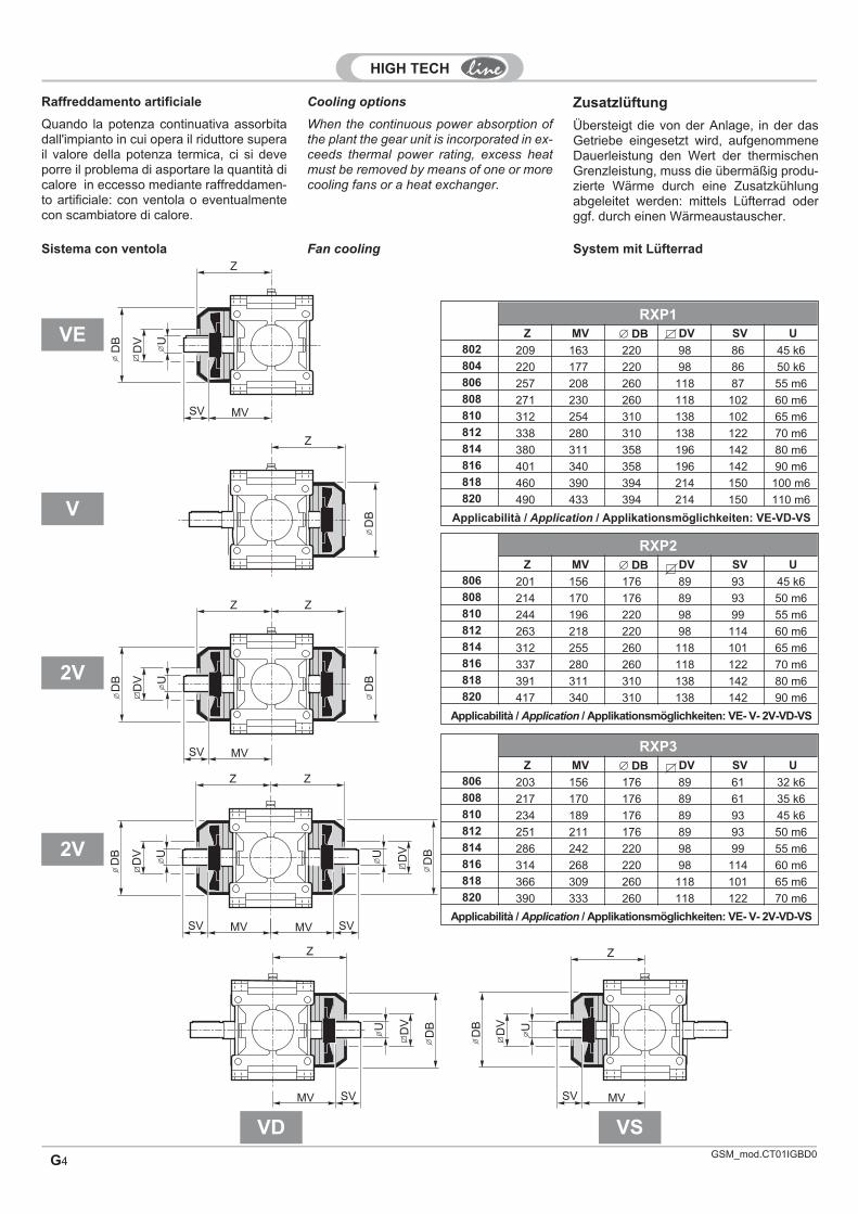
Zusatzlüftung
Übersteigt die von der Anlage, in der dasGetriebe eingesetzt wird, aufgenommeneDauerleistung den Wert der thermischenGrenzleistung, muss die übermäßig produ-zierte Wärme durch eine Zusatzkühlungabgeleitet werden: mittels Lüfterrad oderggf. durch einen Wärmeaustauscher.
Sistema con ventola
RXP1Z MV � DB DV SV U
802 209 163 220 98 86 45 k6804 220 177 220 98 86 50 k6806 257 208 260 118 87 55 m6808 271 230 260 118 102 60 m6810 312 254 310 138 102 65 m6812 338 280 310 138 122 70 m6814 380 311 358 196 142 80 m6816 401 340 358 196 142 90 m6818 460 390 394 214 150 100 m6820 490 433 394 214 150 110 m6
Applicabilità / Application / Applikationsmöglichkeiten: VE-VD-VS
RXP2Z MV � DB DV SV U
806 201 156 176 89 93 45 k6808 214 170 176 89 93 50 m6810 244 196 220 98 99 55 m6812 263 218 220 98 114 60 m6814 312 255 260 118 101 65 m6816 337 280 260 118 122 70 m6818 391 311 310 138 142 80 m6820 417 340 310 138 142 90 m6
Applicabilità / Application / Applikationsmöglichkeiten: VE- V- 2V-VD-VS
RXP3Z MV � DB DV SV U
806 203 156 176 89 61 32 k6808 217 170 176 89 61 35 k6810 234 189 176 89 93 45 k6812 251 211 176 89 93 50 m6814 286 242 220 98 99 55 m6816 314 268 220 98 114 60 m6818 366 309 260 118 101 65 m6820 390 333 260 118 122 70 m6
Applicabilità / Application / Applikationsmöglichkeiten: VE- V- 2V-VD-VS
VE
V
2V
VD VS
U
SV MV
DV
DB
Z
DB
DB
UU
SV
SV
MV
MV
DV
DV
DB
DB
Z
Z
Z
Z
Z
Z Z
SV
SV
SVMV
MV
MV
UU
UDV
DV
DV
DB
DB
DB
2V
Raffreddamento artificiale
Quando la potenza continuativa assorbitadall'impianto in cui opera il riduttore superail valore della potenza termica, ci si deveporre il problema di asportare la quantità dicalore in eccesso mediante raffreddamen-to artificiale: con ventola o eventualmentecon scambiatore di calore.
Cooling options
When the continuous power absorption ofthe plant the gear unit is incorporated in ex-ceeds thermal power rating, excess heatmust be removed by means of one or morecooling fans or a heat exchanger.
Fan cooling System mit Lüfterrad

G5
RXO2 - RXV2
G1 G2 G3 G4 � DB DVSV
RX02i � 47.5
SVRX02i � 47.5
U
806 563 529 281 244 176 89 31 31 28 k6808 634 596 314 276 220 98 30 30 32 k6810 704 666 344 306 220 98 37 37 35 k6812 782 746 377 341 220 98 70 44 40 k6814 883 843 433 393 260 118 80 42 45 k6816 983 943 477 438 260 118 90 52 50 k6818 1113 1058 543 488 310 138 100 62 55 m6820 1231 1178 591 538 310 138 112 74 60 m6
RXO1 - RXV1
G1 G2 G3 G4 � DB DVSV
Ui<11 i<12 i<13 i>11 i>12 i>13
802 403 369 278 244 176 89 31 31 28 j6804 454 416 314 276 220 98 30 30 32 k6806 504 466 343 306 220 98 37 37 35 k6808 557 521 377 341 220 98 70 44 40 k6810 633 585 433 385 260 118 80 50 45 k6812 702 655 477 430 260 118 90 60 50 m6814 793 738 543 488 310 138 100 62 55 m6816 871 818 591 538 310 138 112 74 60 m6818 1009 930 689 610 394 214 125 75 70 m6820 1116 1040 756 680 394 214 140 90 80 m6
U
U
SV
SV
DV
DV
DB
DB
G1
G2
G3
G4
U
U
SV
SV
DV
DV
DB
DB
G1
G2
G3
G4
VE
VE
G
GSM_mod.CT01IGBD0.2
GSM_mod.CT01IGBD0G6
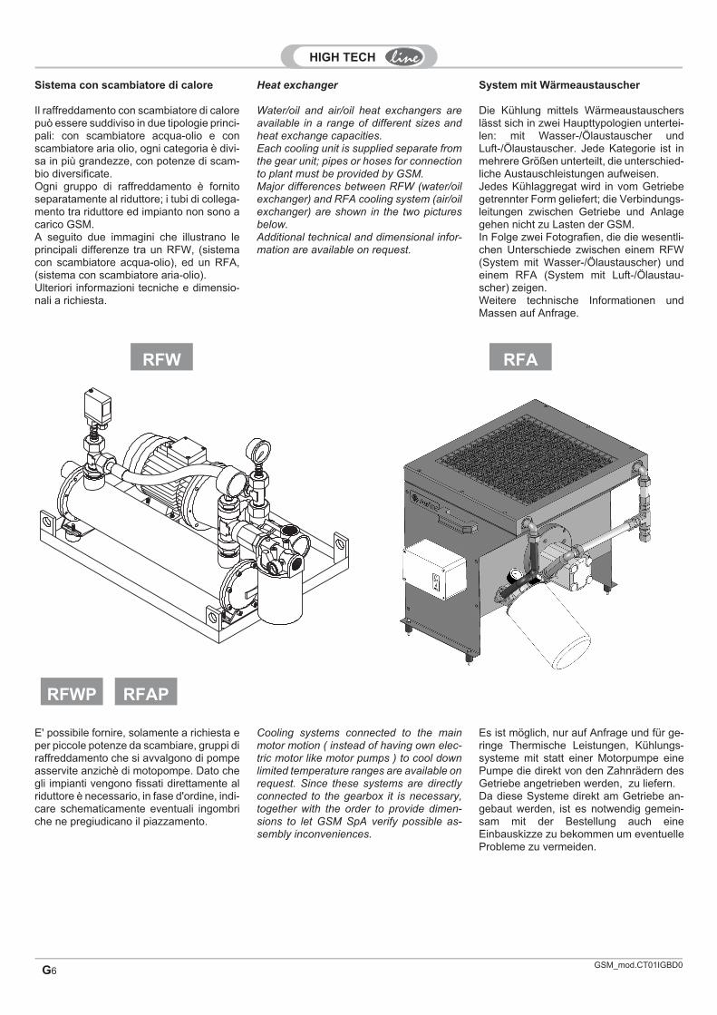
Sistema con scambiatore di calore
Il raffreddamento con scambiatore di calorepuò essere suddiviso in due tipologie princi-pali: con scambiatore acqua-olio e conscambiatore aria olio, ogni categoria è divi-sa in più grandezze, con potenze di scam-bio diversificate.Ogni gruppo di raffreddamento è fornitoseparatamente al riduttore; i tubi di collega-mento tra riduttore ed impianto non sono acarico GSM.A seguito due immagini che illustrano leprincipali differenze tra un RFW, (sistemacon scambiatore acqua-olio), ed un RFA,(sistema con scambiatore aria-olio).Ulteriori informazioni tecniche e dimensio-nali a richiesta.
RFA
System mit Wärmeaustauscher
Die Kühlung mittels Wärmeaustauscherslässt sich in zwei Haupttypologien untertei-len: mit Wasser-/Ölaustauscher undLuft-/Ölaustauscher. Jede Kategorie ist inmehrere Größen unterteilt, die unterschied-liche Austauschleistungen aufweisen.Jedes Kühlaggregat wird in vom Getriebegetrennter Form geliefert; die Verbindungs-leitungen zwischen Getriebe und Anlagegehen nicht zu Lasten der GSM.In Folge zwei Fotografien, die die wesentli-chen Unterschiede zwischen einem RFW(System mit Wasser-/Ölaustauscher) undeinem RFA (System mit Luft-/Ölaustau-scher) zeigen.Weitere technische Informationen undMassen auf Anfrage.
Heat exchanger
Water/oil and air/oil heat exchangers areavailable in a range of different sizes andheat exchange capacities.Each cooling unit is supplied separate fromthe gear unit; pipes or hoses for connectionto plant must be provided by GSM.Major differences between RFW (water/oilexchanger) and RFA cooling system (air/oilexchanger) are shown in the two picturesbelow.Additional technical and dimensional infor-mation are available on request.
RFW
RFAPRFWP
E' possibile fornire, solamente a richiesta eper piccole potenze da scambiare, gruppi diraffreddamento che si avvalgono di pompeasservite anzichè di motopompe. Dato chegli impianti vengono fissati direttamente alriduttore è necessario, in fase d'ordine, indi-care schematicamente eventuali ingombriche ne pregiudicano il piazzamento.
Cooling systems connected to the mainmotor motion ( instead of having own elec-tric motor like motor pumps ) to cool downlimited temperature ranges are available onrequest. Since these systems are directlyconnected to the gearbox it is necessary,together with the order to provide dimen-sions to let GSM SpA verify possible as-sembly inconveniences.
Es ist möglich, nur auf Anfrage und für ge-ringe Thermische Leistungen, Kühlungs-systeme mit statt einer Motorpumpe einePumpe die direkt von den Zahnrädern desGetriebe angetrieben werden, zu liefern.Da diese Systeme direkt am Getriebe an-gebaut werden, ist es notwendig gemein-sam mit der Bestellung auch eineEinbauskizze zu bekommen um eventuelleProbleme zu vermeiden.
GSM_mod.CT01IGBD0 G7
Lubrificazione forzata
Dove necessario è possibile fornire riduttoripredisposti o completi di lubrificazione for-zata. La lubrificazione forzata può essereeffetuata con Pompa asservita o con Moto-pompa.
Pompa asservita
Queto sistema si realizza accoppiando lapompa direttamente ad un albero del ridut-tore, dal quale prende il moto, e si suddividein 3 tipologie.
Motopompa
Questo sistema si realizza accoppiando unmotore elettrico ad una pompa idraulica; sisuddivide in 5 tipologie ed è fornibile ancheseparatamente al riduttore. Nelle tabellesottostanti sono indicate le principali carat-teristiche tecniche e le dimensioni di questiimpianti.
LFP3LFP1
N.B.: la GSM si riserva di scegliere la tipologia piùadatta di Pompa asservita e Motopompa per il buonfunzionamento del riduttore.
LFP2
Pompa con portata di 1.75 I/min a 750 rpmQuesta pompa è particolarmente indicata per un funzionamento a bassonumero di giri, viene ad esempio utilizzata nel primo stadio di riduzionecilindrico di un riduttore ortogonale.Pump with 1.75 I/min capacity at 750 rpmThis pump is especially suited for low speed operation. A typical applicationis the first reduction spur gear set of a helical bevel gear unit.
Pumpe mit Durchsatz von 1,75 I/min bei 750 U/minDiese Pumpe ist besonders für einen Betrieb bei niedriger Drehzahlgeeignet. Sie wird z.B. in der ersten zylindrischen Übersetzungsstufe einesKegelstirnradgetriebes verwendet.
I/min Motor P(kW) A AB AD BB C H LB LP P SB IN OUT VTCELFM1 0.5
71A4 0.25 172135 108 109 45 71 220 130 160 15 1/4"GAS 1/4"GAS M8
LFM2 5 135 108 109 45 71 220 147 160 15 3/8"GAS 3/8"GAS M8LFM3 10 80A4 0.55
197155 120 125 50 80 238 200 200 25 1/2"GAS 1/2"GAS M10
LFM4 20 80B4 0.75 155 120 125 50 80 238 210 200 25 3/4"GAS 1/2"GAS M10LFM5 30 90S4 1.1 214 170 131 154 56 90 255 225 200 25 3/4"GAS 1/2"GAS M12
OUT IN
TCE
C
LP LB P
AB=
AD
HS
B
=
Zwangsschmierung
Wo erforderlich können die Getriebe füreine Zwangsschmierung ausgelegt oderbereits damit ausgestattet geliefert werden.Die Zwangsschmierung kann durch eineNeben- oder Motorpumpe gestellt werden.
Nebenpumpe
Dieses System wird durch die direkte Pas-sung der Pumpe auf eine der Getriebewel-len, von der sie dann auch angetrieben wird,gestellt. Hier unterscheidet man 3 Typen.
Forced lubrication
Where necessary, gear units are suppliedwith provisions for or incorporated forcedlubrication. Both shaft-driven and motor-dri-ven pumps are available.
Shaft-driven pump
The pump is coupled directly to and drivenby a gear unit shaft. There are three diffe-rent types of pumps available.
Motorpumpe
Dieses System wird durch die Passung einesElektromotors an eine Hydraulikpumpe reali-siert; es lässt sich in 5 Typologien unterteilenund kann auch getrennt vom Getriebe geliefertwerden. In den nachstehenden Tabellen wer-den die wesentlichen technischen Eigenschaf-ten und die Maße dieser Anlagen angegeben.
Motor pump
This is a hydraulic pump coupled with anelectric motor. Available in five differenttypes, motor pumps are also offered as aseparate product. Listed in the tables beloware the most significant specifications anddimensions.
HINWEIS: Die STM behält sich das Recht vor, den fürden guten Getriebebetrieb angemessenen Typ derNeben- oder Motorpumpe wählen zu können.
NOTE: STM reserves the right to select the type ofshaft-driven or motor pump deemed most appropriatefor proper gear unit operation at its discretion.
LFM
Pompa con portata di 0.5 I/min a 1500 rpmPump with 0.5 I/min capacity at 1500 rpmPumpe mit Durchsatz von 0,5 I/min bei 1500 U/min
Pompa con portata di 5 I/min a 1500 rpmPump with 5 I/min capacity at 1500 rpmPumpe mit Durchsatz von 5 I/min bei 1500 U/min G

GSM_mod.CT01IGBD0G8
Anelli di tenuta
VT1
VT2
LB2
Grasso / Grease / Fett
LB1
Tutte le suddette descrizioni possono esse-re implementate da queste particelle:
Tenuta a labirinto in entrataLabyrinth seal at input endLabyrinthdichtung im Antrieb
Paraoli in viton in uscitaViton oil seals at output endViton-Dichtung im Abtrieb
DT1Doppia tenuta in entrataDouble seal at input endDoppeldichtung im Antrieb
DT
DT2Doppia tenuta in uscitaDouble seal at output endDoppeldichtung im Abtrieb
Doppia tenuta in entrata ed in uscitaDouble seal at input and output endDoppeldichtung in An- und Abtrieb
LB
VT
Tenuta a labirinto in entrata ed in uscitaLabyrinth seal at input and output endLabyrinthdichtung in An- und Abtrieb
Tenuta a labirinto in uscitaLabyrinth seal at output endLabyrinthdichtung im Abtrieb
Paraoli in viton in entrata ed in uscitaViton oil seals at input and output endViton-Dichtung in An- und Abtrieb
Paraoli in viton in entrataViton oil seals at input endViton-Dichtung im Antrieb
Esecuzione STANDARDUn solo anello di tenuta con labbro parapolvere
STANDARD sealOne dust lip seal
ESTANDARD-AusführungEin einziger Dichtring mit Staubstreiferlippe
Grasso / Grease / Fett
DichtringeSeals
Alle o.g. Beschreibungen können durch diefolgenden Teile implementiert werden:
All of the above items are implemented bythese designation elements:
Coperchio di protezione
PROT
Coperchio di protezione per estremità ro-tanti a richiesta.
Protection cover Schultzvorrichtungdeckel
On request, an output shaft protection co-ver can be supplied.
Auf Anfrage ist eine Schutzabdeckung fürdie Abtriebswellen lieferbar.
GSM_mod.CT01IGBD0 G9
Flangia freno (a disegno cliente)
A richiesta è possibile una predisposizioneper poter assemblare direttamente diversetipologie di freno al riduttore.
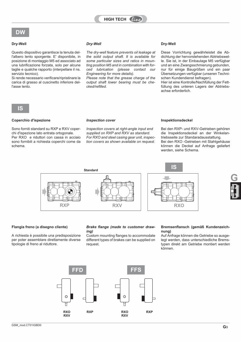
IS
RXP RXV RXO
Standard
DW
Dry-Well
Questo dispositivo garantisce la tenuta del-l'albero lento sporgente. E' disponibile, inposizione di montaggio M5 ed associato aduna lubrificazione forzata, solo per alcunetaglie e qualche rapporto (interpellare il ns.servizio tecnico).Si rende necessario verificare/ripristinare lacarica di grasso al cuscinetto inferiore del-l'asse lento.
IS
Coperchio d'ispezione
Sono forniti standard su RXP e RXV coper-chi d'ispezione lato entrata ortogonale.Per RXO e riduttori con cassa in acciaiosono fornibili a richiesta coperchi come daschema.
FFD FFS
RXORXV
RXP RXORXV
RXP
Brake flange (made to customer draw-
ing)Custom mounting flanges to accommodatedifferent types of brakes can be supplied onrequest.
Dry-Well
The dry-well feature prevents oil leakage atthe solid output shaft. It is available forsome particular sizes and ratios in moun-ting position M5 and in combination with for-ced lubrication (please contact ourEngineering for more details).Please note that the grease charge of theoutput shaft lower bearing must be che-cked/refilled.
Inspection cover
Inspection covers at right-angle input endsupplied on RXP and RXV as standard.For RXO and steel casing gear unit, inspec-tion covers as shown available on request.
Bremsenflansch (gemäß Kundenzeich-nung)Auf Anfrage können die Getriebe so ausge-legt werden, dass unterschiedliche Brems-typen direkt am Getriebe montiert werdenkönnen.
Dry-Well
Diese Vorrichtung gewährleistet die Ab-dichtung der hervorstehenden Abtriebswel-le. Sie ist, in der Einbaulage M5 verfügbarund an eine Zwangsschmierung gebunden,nur für einige Baugrößen und ein paarÜbersetzungen verfügbar (unseren Techni-schen Kundendienst befragen).Hier ist eine Kontrolle/Nachfüllung der Fett-füllung des unteren Lagers der Abtriebs-achse erforderlich.
Inspektionsdeckel
Bei den RXP- und RXV-Getrieben gehörendie Inspektionsdeckel an der Winkelan-triebsseite zur Standaradausstattung.Bei den RXO -Getrieben mit Stahlgehäusekönnen die Deckel auf Anfrage geliefertwerden, siehe Schema.
G

GSM_mod.CT01IGBD0G10
BM2
BM3
Bussole in VKL
A richiesta le basi di tipologia BM1 e BM2sono equipaggiabili con bussole in VKL. Aseguito le dimensioni delle bussole in corri-spondenza alla taglia del riduttore.
Base porta motore
A richiesta sono disponibili 3 tipologie dibasi porta motore. Nelle figure a seguitosono illustrate le forme costruttive delle 3famiglie principali di questo prodotto.Nelletipologie BM1 e BM2 sono fornibili comeconnessioni tra motore e riduttore giuntiidrodinamici e giunti elastici, eventualmenteequipaggiati con dischi a freno.
D d Sp
80865 40 88
810812
80 50 110814816
100 140 120818820
110 160 180822
D d
(u1
0)
(H9
)
Sp ( 0.6)
BM1
VKL-Buchsen
Auf Anfrage können die Typologien BM1und BM2 mit VKL-Buchsen ausgestattetwerden. Nachstehend die für die Getriebe-größen passenden Buchsenmaße.
Motor mount
Three types of motor mounts are availableon request. The diagrams below showthree major families of motor mount prod-ucts. On request, fluid and flexible cou-plings, also equipped with brake discs, areprovided with types BM1 and BM2.
Motorauflage
Auf Anfrage sind 3 Typologien von Motor-auflagen verfügbar. Auf den folgenden Ab-bildungen werden die Bauformen der dreiHauptfamilien dieses Produkts illustriert.Die Typologien BM1 und BM2 können alsVerbindungen zwischen Motor und Getrie-be als hydrodynamische und elastischeKupplungen, eventuell mit Scheibenbrem-sen ausgestattet geliefert werden.
VKL bush
On request, motor mounts BM1 and BM2can be equipped with VKL bushes. Bush di-mensions for the different gear unit sizesare given in the table.

GSM_mod.CT01IGBD0 G11
Personalizzazione generica
S
La GSM si riserva di inserire questa parti-cella per indicare una personalizzazioneparticolare non indicata a catalogo;(adesempio RXP3/818 S per indicare un ridut-tore con cassa in acciaio e dimensioni di-verse da quelle previste a catalogo.
Accessori idraulici
AI
Allgemeine Personalisierung
Die STM hat diese Bezeichnung eingeführt,um damit eine besondere, nicht im Katalogangegebene Personalisierung angeben zukönnen (z.B. steht RXP3/818 S für ein Ge-triebe mit Stahlgehäuse und von den Kata-logangaben abweichenden Maßen).
Hydraulikzubehör
Special custom version
This designation element may be used atSTM's discretion to identify special customversions not listed in the catalogue; for in-stance, RXP3/818 S would be used toidentify a steel casing gear unit withnon-standard dimensions.
Hydraulic accessories
Filtro olioOil filterÖlfilter
Rubinetto olioOil tapÖlhahn
Asta livello olioOil dipstickÖlmessstab
Visore livello olioOil sight glassÖlschauglas
Tappi ausiliariAuxiliary plugsSchrauben
Sfiato antipolvereDust/breather plugStaubentlüftung
Livellostato visivoLevel switch with sight windowSchauglas
Livellostato a galleggianteFloat level switchPegelwächter
PressostatoPressure switchDruckschalter
TermostatoTemp. switchThermostat
Flussostato visivoFlow switch and sight flow indicatorDurchflusswächter mit Sichtanzeige
FlussostatoFlow switchDurchflusswächter
RiscaldatoreHeaterHeizelement
Sonda PT100PT100 sensorSonde PT100
Filtro elettricoElectric filterElektrofilter
Serpentina di raffreddamentoCooling coilKühlschlange
G

GSM_mod.CT01IGBD0G12
Uscita speciale
US
Sono fornibili a richiesta estremità in uscitadiverse da quelle indicate a catalogo
Flange di uscita
Sono previste flange da impiegare qualorasi desideri il fissaggio diretto del riduttorealla macchina. La soluzione è molto com-patta, la battuta dell'albero lento non è mo-dificata rispetto allo standard.
N.B.: tale soluzione non è disponibile perRXO1, RXV1 e RXP1.
A B � Ch7 D E F G M � T R
802 250 215 180 155 14 18 5 109 60 112804 300 265 230 175 14 18 5 121 70 125806 350 300 250 195 16 20 5 137 80 140808 350 300 250 215 16 22 5 151 90 160810 400 350 300 240 16 22 5 170 100 180812 450 400 350 270 16 24 5 192 110 200814 550 500 450 300 18 27 7 216 125 225816 550 500 450 340 20 30 7 242 140 250818 660 600 550 375 22 33 7 273 160 280820 660 600 550 410 22 36 7 302 180 315
TH
7
Tm
6
D
MB R
A
G
EF
C
size 810 size 808
Spezialabtrieb
Auf Anfrage sind von den Katalogangabenabweichende Abtriebswellenenden liefer-bar.
Abtriebsflansch
Es sind Flanschen vorgesehen, die danneinzusetzen sind, wenn eine direkte Befes-tigung des Getriebes an der Maschine ge-wünscht wird. Bei dieser Lösung handelt essich um eine sehr kompakte Form, der Ab-triebswellenansatz ist dem standardmäßi-gen Ansatz gleich.
HINWEIS: Diese Lösung ist für die GetriebeRXO1, RXV1 und RXP1 nicht verfügbar.
Special output
Output configurations other than thoselisted in the catalogue available on request
Output flanges
Output flanges are available forflange-mount configuration. This provides acompact design; standard output shaftshoulder dimensions are unchanged.
NOTE: This configuration is not availablefor RXO1, RXV1 and RXP1.
FNd FNs 2FN FCd FCs 2FCFBsFUs
FBdFUd

GSM_mod.CT01IGBD0 G13
Supportazioni rinforzate
È possibile dotare i riduttori standard, sia adassi paralleli che ortogonali, di sopportazio-ne rinforzata sull'albero lento ottenendouna soluzione ottimale per applicazioniquali: mixers, agitatori, ventilatori, aeratori etorri di raffreddamento. Adottando cuscinet-ti a rulli di elevata capacità di carico mag-giormente distanziati sull'albero e unrobusto e rigido supporto esterno è consen-tito un notevole aumento dei carichi radiali eassiali ammissibili. A richiesta sono fornibilitenute a labirinto e la lubrificazione forzatadei cuscinetti in alto.
T(m6) R MI N/2 HC DC
(h7)
804 70 125 200 118.5 143 185
806 80 140 225 134.5 160 210
808 90 160 250 148.5 176 235
810 100 180 280 167.5 192 255
812 110 200 315 189.5 220 290
814 125 225 355 213.5 245 320
816 140 250 400 239.5 271 370
818 160 280 450 270.5 300 420
820 180 315 500 299.5 315 450
N.B.: La stessa tipologia di applicazione èdisponibile anche per RXP ed RXO di diver-si stadi di riduzione e forme costruttive.Le grandezze 804 ed 806 non sono fornibilicon pompa asservita.
MX
N/2
MIH
C
R
T
DC
Verstärkte Lagerung
Die Standard-Getriebe, sowohl die Parallel-achsengetriebe als auch die Kegelradge-triebe, können mit einer verstärktenLagerung der Abtriebswelle ausgestattetwerden. Dadurch wird eine optimale Lö-sung bei gewissen Applikationen erzielt,z.B. bei Rührwerken, Mischwerken, Venti-latoren, Belüftern und Kühltürmen. Durchden Einsatz von auf der Welle weiter von-einander distanzierten Rollenlagern mit ho-her Belastungskapazität und einerrobusten und steifen externen Lagerungkönnen die zulässigen Radial- und Axial-kräfte erheblich gesteigert werden. Auf An-fragen können Labyrinthdichtungen undeine Zwangsschmierung der obenliegen-den Lager geliefert werden.
Heavy duty output bearings
Standard in-line helical and helical bevelgear units are available in heavy duty con-figuration for such applications as mixers,agitators, fans, aerators and cooling tow-ers. Heavy duty roller bearings, wider bear-ing span and a sturdy bearing blockensuring high rigidity significantly increaseoverhung and thrust load capacities. Laby-rinth seals and forced lubrication for upperbearings available on request.
HINWEIS: Diese Applikationstypologie istauch für die RXP- und RXO-Getriebe mitunterschiedlichen Übersetzungsstufen undBauformen verfügbar.
NOTE: The same configuration is also avai-lable for RXP and RXO units in different re-duction and design versions.Sizes 804 and 806 are not available withshaft-driven pump.
G
GSM_mod.CT01IGBD0G14
N/2
MI
MP
R
T
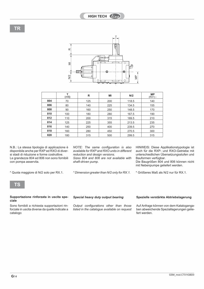
TR
T(m6) R MI N/2 MP
(RX1) *
804 70 125 200 118.5 140
806 80 140 225 134.5 155
808 90 160 250 148.5 170
810 100 180 280 167.5 190
812 110 200 315 189.5 210
814 125 225 355 213.5 235
816 140 250 400 239.5 270
818 160 280 450 270.5 300
820 180 315 500 299.5 315
N.B.: La stessa tipologia di applicazione èdisponibile anche per RXP ed RXO di diver-si stadi di riduzione e forme costruttive.Le grandezze 804 ed 806 non sono fornibilicon pompa asservita.
* Quota maggiore di N/2 solo per RX.1.
Sono fornibili a richiesta supportazioni rin-forzate in uscita diverse da quelle indicate acatalogo
TS
Supportazione rinforzata in uscita spe-ciale
HINWEIS: Diese Applikationstypologie istauch für die RXP- und RXO-Getriebe mitunterschiedlichen Übersetzungsstufen undBauformen verfügbar.Die Baugrößen 804 und 806 können nichtmit Nebenpumpe geliefert werden.
* Größeres Maß als N/2 nur für RX.1.
Auf Anfrage können von dem Kataloganga-ben abweichende Speziallagerungen gelie-fert werden.
Spezielle verstärkte Abtriebslagerung
NOTE: The same configuration is alsoavailable for RXP and RXO units in differentreduction and design versions.Sizes 804 and 806 are not available withshaft-driven pump.
* Dimension greater than N/2 only for RX.1.
Output configurations other than thoselisted in the catalogue available on request
Special heavy duty output bearing

GSM_mod.CT01IGBD0 G15
D1
*
D*
Tm
6
TH
7
Q
M
S
P
G G
G
R
N
F
F G M N P Q R S T
802 16 228 300 250 350 4 112 16 60
804 16 248 300 250 350 4 125 18 70
806 18 268 350 300 400 5 140 18 80
808 18 303 400 350 450 5 160 20 90
810 20 333 450 400 500 6 180 20 100
812 20 372 500 450 550 6 200 22 110
814 22 407 550 500 600 7 225 22 125
816 25 452 600 550 650 7 250 25 140
818 27 502 650 600 700 8 280 25 160
820 30 551 750 650 800 8 315 28 180
SND SNS SCD SCS
SUD SUS SBD SBS
: Esempio di applicazione: Application example: Appikationsbeispiel
* Le dimensioni dell'albero cavo con unità di bloccaggiosono riportate a pag. F6.
N.B.: Tali soluzioni non sono applicabili per RXO1, RXV1 eRXP1.
* Die Maße der Hohlwelle mit Schrumpfscheibe werden aufSeite F6 angegeben.
HINWEIS: Diese Lösungen sind für die Getriebe RXO1, RXV1und RXP1 nicht anwendbar.
* Dimensions of hollow shaft with shrink disc are providedat page. F6.
NOTE: These configurations are not available for RXO1, RXV1and RXP1.
G

GSM_mod.CT01IGBD0G16
A
B C
D
E F
Molle a tazzaBelleville washers
Tellerfedern
RXP1RX01RXV1
RXP2RX02RXV2
RXP3RX03RXV3
MIN MAXN. 4 Molle a tazza
4 Belleville washers
4 Tellerfedern
Y (*)
802 175 225 318 20 M16 25 38 13 90 50x25.4x2.5 0.6804 196 286 355.5 20 M16 25 38 13 100 50x25.4x2.5 0.6806 222 322 402 24 M20 29 45 16 112.5 63x31x3.5 0.8808 250 362 452 24 M20 29 45 16 125 63x31x3.5 0.8810 280 405 504 30 M24 29 45 19 140 70x35.5x4 0.8812 315 455 566.5 30 M24 29 45 19 157.5 70x35.5x4 0.8814 350 510 634 36 M30 37 70 23 177.5 100x51x5 1816 393 573 712.5 39 M33 37 70 23 200 100x51x5 1818 445 645 805 39 M33 45 70 23 225 100x51x5 1820 500 725 904.5 42 M36 45 80 29 250 125x61x6 1.3
F
ED B
AC
Kit bullone di reazione
Kit rosetta di montaggio
nU
Riduttori con più alberi uscita
A richiesta è possibile fornire riduttori conpiù assi di uscita. Tipica è l'applicazione deilaminatoi dove si hanno 2 assi di uscita con-trorotanti; in questo caso la descrizionesarà 2U.
Kit Momentenstütze
Kit Montagescheibe
Getriebe mit mehreren Abtriebswellen
Auf Anfrage können Getriebe mit mehrerenAbtriebsachsen geliefert werden. Typischist hier die Applikation in Walzwerken , woman 2 gegeneinander rotierende Abtriebs-achsen einsetzt; in diesem Fall ist die Be-zeichung 2U.
Torque arm kit
Mounting washer kit
Gear unit with several output shafts
Gear units with more than one output shaftsare available on request. A typical applica-tion is a rolling mill requiring a gear unit withtwo counter-rotating shafts; the corre-sponding designation will be 2U.
(*) Valore di compressione delle molle (*) Spring compression value (*) Wert der Federkompression

G17
ESTREMITÀ SUPPLEMENTARI
A richiesta è possibile fornire riduttori conestremità supplementari, in tali casi deveessere indicata la designazione dell'ES(estremità supplementare) come indicato inseguito.
[13*] [14*] [15*] [16*] [17*]
ES 2 DX 506 PAM132
Estremità supplementareAdditional shaft extension
Zusätzliches Wellenende
AsseAxis
Achse
Posizione estremitàsupplementare
Additional shaft extensionposition
Position des zusätzlichenWellenendes
ies
Tipologia di entrataInput configuration
Antriebstyp
ES 1 - 2- 3 DX - SXRapporto realedall'estremità
supplementare
ECEECESPAM..
PAM..G
Designazione / Designation / Bezeichnung
[13*] Presenza di un'estremitàsupplementare
[14*] Asse dov' è presente l'estremitàsupplementare
[15*] Lato estremità supplementare
RXORXO1 RXO2 RXO3
RXV
32
3
RXP
32
1
3 32 2
3
1
RXV1
RXP1
RXV2
RXP2
RXV3
RXP3 RXP4
23
1
RXO1 RXO2 RXO3
RXV1
RXP1
RXV2
RXP2
RXV3
RXP3 RXP4
SX
SX
SX
DX
DX
DX
[16*] Rapporto reale del riduttore dallaestremità supplementare
Comunicato da GSM su richiesta.
ADDITIONAL SHAFTEXTENSIONSOn request, gear units are available withadditional shaft extensions; please specifythe designation of the required ES (additio-nal shaft extension) as outlined below.
ZUSÄTZLICHEWELLENENDENAuf Anfrage können die Getriebe mitzusätzlichen Wellenenden geliefert wer-den, in diesen Fällen muss wie folgt die Be-zeichnung ES (steht für zusätzlichesWellenende) angegeben werden.
[13*] Additional shaft extension fitted
[14*] Axis where additional shaft
extension is located
[13*] Ein zusätzliches Wellenendevorhanden
[14*] Acahse an der ein zusätzlichesWellenende vorhanden ist
[15*] Additional shaft extension side
[16*] Actual gear ratio of gear unit from
additional shaft extension
Information available from GSM on request.
[15*] Seite des zusätzlichen Wellenendes
[16*] Reelles Übersetzungsverhältnisam zusätzlichen Wellenende
Gibt GSM auf Anfrage an.
G
GSM_mod.CT01IGBD0.1

GSM_mod.CT01IGBD0G18
[17*] Tipologia di estremitàsupplementare
PAM..ECE PAM..G
ECE Entrata con albero pieno Solid input shaft Antrieb mit Vollwelle
ECES Entrata con estremità speciale (disponibile a richiesta) Special input shaft end (available on request) Antrieb mit speziellem Wellenende (auf Anfrage verfügbar)
PAM.. Con campana senza giunto Motor bell without coupling Mit Glocke ohne Kupplung
PAM..G Con campana e giunto Motor bell and coupling Mit Glocke und Kupplung
Dimensioni
MS
U
GrandezzaSize
Größe
TipoTypeTyp
Asse / Axis / Achse
1 2 3U S M U S M U S M
802
RXO1-RXV1 — — — — — — 35 k6 63 137RXP2 — — — — — — 35 k6 63 109RXO2-RXV2-RXP3 — — — 28 j6 50 109 35 k6 63 109RXO3-RXV3-RXP4 22 j6 40 109 28 j6 50 109 35 k6 63 109
804
RXO1-RXV1 — — — — — — 40 k6 70 151RXP2 — — — — — — 40 k6 70 121RXO2-RXV2-RXP3 — — — 32 k6 56 121 40 k6 70 121RXO3-RXV3-RXP4 24 j6 45 121 32 k6 56 121 40 k6 70 121
806
RXO1-RXV1 — — — — — — 45 k6 80 170RXP2 — — — — — — 45 k6 80 137RXO2-RXV2-RXP3 — — — 35 k6 63 137 45 k6 80 137RXO3-RXV3-RXP4 28 j6 50 137 35 k6 63 137 45 k6 80 137
808
RXO1-RXV1 — — — — — — 50 k6 90 192RXP2 — — — — — — 50 k6 90 151RXO2-RXV2-RXP3 — — — 40 k6 70 151 50 k6 90 151RXO3-RXV3-RXP4 32 k6 56 151 40 k6 70 151 50 k6 90 151
810
RXO1-RXV1 — — — — — — 55 m6 100 216RXP2 — — — — — — 55 m6 100 170RXO2-RXV2-RXP3 — — — 45 k6 80 170 55 m6 100 170RXO3-RXV3-RXP4 35 k6 63 170 45 k6 80 170 55 m6 100 170
812
RXO1-RXV1 — — — — — — 60 m6 112 242RXP2 — — — — — — 60 m6 112 192RXO2-RXV2-RXP3 — — — 50 k6 90 192 60 m6 112 192RXO3-RXV3-RXP4 40 k6 70 192 50 k6 90 192 60 m6 112 192
814
RXO1-RXV1 — — — — — — 70 m6 125 273RXP2 — — — — — — 70 m6 125 216RXO2-RXV2-RXP3 — — — 55 m6 100 216 70 m6 125 216RXO3-RXV3-RXP4 45 k6 80 216 55 m6 100 216 70 m6 125 216
816
RXO1-RXV1 — — — — — — 80 m6 140 302RXP2 — — — — — — 80 m6 140 242RXO2-RXV2-RXP3 — — — 60 m6 112 242 80 m6 140 242RXO3-RXV3-RXP4 50 k6 90 242 60 m6 112 242 80 m6 140 242
818
RXO1-RXV1 — — — — — — 90 m6 160 273RXP2 — — — — — — 90 m6 160 273RXO2-RXV2-RXP3 — — — 70 m6 125 273 90 m6 160 273RXO3-RXV3-RXP4 55 m6 100 273 70 m6 125 273 90 m6 160 273
820
RXO1-RXV1 — — — — — — 100 m6 180 302RXP2 — — — — — — 100 m6 180 302RXO2-RXV2-RXP3 — — — 80 m6 140 302 100 m6 180 302RXO3-RXV3-RXP4 60 m6 112 302 80 m6 140 302 100 m6 180 302
Dimensions Applizierbare Motoren
[17*] Additional shaft extension type [17*] Typ des zusätzlichen Wellenendes

GSM_mod.CT01IGBD0 G19
IEC80 90 100 112 132 160 180 200 225 250 280 315 355
D H7 19 24 28 28 38 42 48 55 60 65 75 80 100
P 200 200 250 250 300 350 350 400 450 550 550 660 800
MN 165 165 215 215 265 300 300 350 400 500 500 600 740
N G6 130 130 180 180 230 250 250 300 350 450 450 550 680
K M10 M10 M12 M12 M12 M16 M16 M16 M16 M16 M16 M16 M20
SP 12 12 14 14 16 18 18 20 20 20 20 24 30
G
802 203 213 213 233 263 263 263
804 230 230 250 280 280 280 310
806 251 251 271 301 301 301 331
808 271 271 291 321 321 321 351 351 351
810 317 347 347 347 377 377 377 407
812 346 376 376 376 406 406 406 436
814 410 410 410 440 440 440 470
816 446 446 446 476 476 476 506 546
818 487 517 517 517 547 587
820 558 558 558 588 628
IEC80 90 100 112 132 160 180 200 225 250 280 315 355
D H7 19 24 28 28 38 42 48 55 60 65 75 80 100
P 200 200 250 250 300 350 350 400 450 550 550 660 800
MN 165 165 215 215 265 300 300 350 400 500 500 600 740
N G6 130 130 180 180 230 250 250 300 350 450 450 550 680
K M10 M10 M12 M12 M12 M16 M16 M16 M16 M16 M16 M16 M20
SP 12 12 14 14 16 18 18 20 20 20 20 24 30
G
802 223 243 273 273 273
804 291 291 291 321
806 314 314 314 344
808 335 335 335 365 365 365
810 364 394 394 394
812 426 426 426 456
814 460 460 490 530
816 498 528 568
818 542 572 612
820 616 656
GMN
D
K
N
P
SU
M
SP
PAM..
PAM..G
SizeIEC 200 IEC 225
Asse / Axis / Achse 1
Asse / Axis / Achse 2
Le altre dimensioni dei riduttori potranno esserereperite nelle corrispondenti sezioni RXP e RXO.
For gear unit dimensions not covered here,please see the relevant RXP and RXO sections.
Die weiteren Abmessungen der Getriebe könnenden jeweiligen Abschnitten RXP und RXOentnommen werden.
G

GSM_mod.CT01IGBD0G20
CAMBI DI VELOCITÀ
A richiesta è possibile fornire riduttori concambio di velocità, in tali casi, nelle desi-gnazioni dei riduttori RXP e RXO riportatenelle rispettive sezioni, in corrispondenza diir (colonna [5*]) deve essere riportato 2V,3V, ... (numero di marce desiderato e rap-porto reale delle rispettive marce) come in-dicato in seguito.
[5*]
2V
ir
2V3V4V...
Designazione
Esempio / Example / Beispiel
RXP2/814/2V 7-14/ECES/N/M1
Designazione / Designation / Bezeichnung
Per configurazioni disponibili, prestazioni edimensioni contattare il servizio tecnicocommerciale GSM.
GEAR SHIFT
Gear-shift drives are available on request;when designating RXP and RXO gear unitsas outlined in the relevant sections, specifynumber of speeds and actual gear ratios(2V, 3V, ...) under item ir (column [5*]) asoutlined below.
SCHALTGETRIEBE
Auf Anfrage können Schaltgetriebe gelie-fert werden, in diesen Fällen muss unterden Bezeichnungen der RXP- und derRXO-Getriebe in den jeweiligen Abschnit-ten, unter der Angabe ir (Spalte [5*]) 2V,3V, ... angegeben werden (Anzahl dergewünschten Gänge und reelles Überset-zungsverhältnis der Gänge); siehenachstehende Angaben.
Please contact GSM Sales Engineers fordetailed information on available configura-tions, ratings and dimensions.
Die verfügbaren Konfigurationen, Leistun-gen und Abmessungen können in der Tec-hnischen Abteilung der STM angefragtwerden.