
1 - Well Clean Up
12
1 S S h hel l l l EP L EP Lear rni ing Copyrig ht2001 SIEP B.V Wel l Cl ean Up C o p y r i g h t 2 0 0 1 S I E P B . V S S h he el l l l EP L EP Le ear rni ing g Why clean up th e well? z Solids initially suspended in the completion fluid will settle under gravity end up sitt ing in top of any barriers in t he well - top p acker can effect fu nction of mo ving equipm ent such as sliding sleeves, safety valves, dynamic seal assemblies etc. z Solids can prevent the release of anchor latches and retrievable packers z During completion operations solids in the completion fluid can cause problems solids on top of w ireline plug could prevent recovery P lug flow pat hs Obstruct seal bores
Transcript of 1 - Well Clean Up

7/29/2019 1 - Well Clean Up
http://slidepdf.com/reader/full/1-well-clean-up 1/12
1
SShheellll EP LEP LeeaarrnniinnggCopyright2001 SIEP B.V
Well Clean Up
C o p y r i g h t 2 0 0 1 S I E P B . V
SShheellll EP LEP Leeaarrnniinngg
Why clean up the well?
z Solids initially suspended in the completion fluid will settle undergravity end up sitting in top of any barriers in the well - top packer can effect function of moving equipment such as sliding sleeves, safety
valves, dynamic seal assemblies etc.
z Solids can prevent the release of anchor latches and retrievablepackers
z During completion operations solids in the completion fluid cancause problems solids on top of wireline plug could prevent recovery Plug flow paths Obstruct seal bores

7/29/2019 1 - Well Clean Up
http://slidepdf.com/reader/full/1-well-clean-up 2/12
2
C o p y r i g h t 2 0 0 1 S I E P B . V
SShheellll EP LEP Leeaarrnniinngg
Elements of hole clean up
zRemoval of solids
zMud displacement
zChemical clean up of Oil Based Muds
C o p y r i g h t 2 0 0 1 S I E P B . V
SShheellll EP LEP Leeaarrnniinngg
Removal of Solids
zRemoval of all drilling solids, prior to mud displacementand chemical clean-up, important for two reasons : removal of drilling solids from a deviated wellbore better
performed with drilling fluid.
base fluid and clean-up chemicals will not remove solid debrisfrom the wellbore.
z Efficient hole cleaning is directly dependent on theability of mud to suspend the drill cuttings and carrythem to the surface.

7/29/2019 1 - Well Clean Up
http://slidepdf.com/reader/full/1-well-clean-up 3/12
3
C o p y r i g h t 2 0 0 1 S I E P B . V
SShheellll EP LEP Leeaarrnniinngg
Factors effecting solids removal
z Annular velocity.
z Hole inclination because of its effect on cuttings beds.
z Mud rheology.
z Sweeps.
z Pipe rotation and reciprocation to counteract settling tendency.
z Wellboregeometry.
z Particle size, shape and density.
C o p y r i g h t 2 0 0 1 S I E P B . V
SShheellll EP LEP Leeaarrnniinngg
Significance of hole inclination
An equilibrium thickness is reached where the rate of bed formation is equal tothe rate of bed erosion. As the flow rate is increased, the bedis de-stabilisedand more cuttings are forced into the flow stream.
50-90 deg
At low flow rates the bed thickness increases with hole angle, reaching amaximum at hole angles within this range.Critical range of hole angles where hole cleaning is more difficult due to thegravity forces causing the cuttings beds to slide downwards against the flow.With no flow rate the cuttings beds tend to avalanche down the wellbore, which
can result in packing off around drill strings.
40-50 deg
cuttings move towards the low side of the annulus resulting in the formation of a cuttings bed.
>10 deg
Similar to that in a vertical wells - no tendency for cuttings to form a bed.0-10 deg
Transport MechanismHole Inclination

7/29/2019 1 - Well Clean Up
http://slidepdf.com/reader/full/1-well-clean-up 4/12
4
C o p y r i g h t 2 0 0 1 S I E P B . V
SShheellll EP LEP Leeaarrnniinngg
Sweeps
z Use of high-viscosity sweeps to improve cuttings removal is
common practice. Hi-vis pills most effective in vertical and low angle wells can be effective in high angle wells if cuttings moved into flow stream need to be disturbed by rotation / reciprocation whilst the hi-vis pill is
passing
z Turbulent (lov Vis) sweeps can help if flow rate is high andvolume of the sweep is large Turbulence can erode existing cuttings beds
if the volume of the sweep is insufficient, cuttings only transported shortdistance before settling back to the low side of the hole
problem can sometimes be overcome by tandem pills (turbulent sweepthen viscous pill).
C o p y r i g h t 2 0 0 1 S I E P B . V
SShheellll EP LEP Leeaarrnniinngg
Pipe Rotation and Reciprocation
z pipe rotation good in high inclination wells: mechanically disturbs cuttings beds, moving solids back into the mud
flow stream for removal. particularly useful in laminar flow, with viscous fluids - particles on the
low side of the hole are moved into the higher flow velocity regions particles can settle and be re-deposited quite quickly if viscosity and gel
strengths are insufficient

7/29/2019 1 - Well Clean Up
http://slidepdf.com/reader/full/1-well-clean-up 5/12
5
C o p y r i g h t 2 0 0 1 S I E P B . V
SShheellll EP LEP Leeaarrnniinngg
Displacement to Completion Fluid
zMud Conditioning prior to displacement
zUse of Displacement Pills
zCentralisation of drillstring
C o p y r i g h t 2 0 0 1 S I E P B . V
SShheellll EP LEP Leeaarrnniinngg
Displacement pill s for OBM
Pill will act like a piston and will displace the wholemud out of the hole. It will help remove solids that haveaccumulated on the low side of the hole, particularly atadverse angles.
100-150bbl
100 bblPush Pill
Used to thin the mud and prevent gelled mud fromsticking to the casing wall. Pill should be treated with 1-2 ppb emulsifier to ensure no solids settlement when
mixed with any gelled mud sticking to the casing wall.
50-100 bbl30 bblBase Oil
Comments
High Mud
Weight or
High
Deviation
Low Mud
Weight &
Low
Deviation
Fluid
• The composition of the push pill should be 3 ppb XC polymer +3 - 5%surfactant in seawater. Aim for YP of approx. 50.
• The displacement flow rate should be such that the base oil is in turbulent
flow and the push pill is in laminar flow.

7/29/2019 1 - Well Clean Up
http://slidepdf.com/reader/full/1-well-clean-up 6/12
6
C o p y r i g h t 2 0 0 1 S I E P B . V
SShheellll EP LEP Leeaarrnniinngg
Pipe Stand Off
z Without centralisation stand-off of most sizes of drillpipe, in adeviated hole section, is below 50%
z Pipe stand-off has impact on: flow rate required to initiate fluid movement critical flow rate for turbulence upper limit of laminar flow in order to avoid by-passing fluid.
C o p y r i g h t 2 0 0 1 S I E P B . V
SShheellll EP LEP Leeaarrnniinngg
Chemical and Mechanical Clean Up
z Aim is to displace oil based drilling fluid from the wellbore leaving the casing‘water wet’, before displacing the well to the completion fluid (inhibitedseawater or brine).
z At end of drilling process, well is usually left full of oily mud
z Mud generally consists of an oily base fluid with water, clay (for viscosity) andbarite / dolomite (for density)
z Emulsifiers - oil wetting agents - in oil phase ensure all surfaces (tubulars,barite, formation) are oil wet, any water is encapsulated as microscopicdroplets.
z When displacing the well to water, not only does the oily mud requiredisplacing, but also the casing surfaces need to be changed from oil wet towater wet.

7/29/2019 1 - Well Clean Up
http://slidepdf.com/reader/full/1-well-clean-up 7/12
7
C o p y r i g h t 2 0 0 1 S I E P B . V
SShheellll EP LEP Leeaarrnniinngg
Removal of Oil
z Water alone will not remove oily mud.
z oily mud is best removed by pumping: solvents, to dissolve any oily residues; surfactants (surface active agents), to change the casing surface from oil
wet to water wet, i.e. counteracting the emulsifiers in the oily mud.
z Chemical pills ideally pumped at maximum pump rate togenerate turbulent flow.
z reasonably long contact times for each pill is required – often asmuch as 10 minutes
z The well is then displaced to inhibited freshwater, seawater orbrine, depending on the completion requirements.
C o p y r i g h t 2 0 0 1 S I E P B . V
SShheellll EP LEP Leeaarrnniinngg
Surfactants

7/29/2019 1 - Well Clean Up
http://slidepdf.com/reader/full/1-well-clean-up 8/12
8
C o p y r i g h t 2 0 0 1 S I E P B . V
SShheellll EP LEP Leeaarrnniinngg
Mechanical Tools
zMechanical tool strings aide chemicals during theclean-up process
z generally of a scraper, a brush or a combination of both
zHistorically used conventional drilling equipment
zMore recently, purpose designed equipment on market
C o p y r i g h t 2 0 0 1 S I E P B . V
SShheellll EP LEP Leeaarrnniinngg
Mechanical Clean-Up Tools
360 deg Scraper
WellborePatroller
7/29/2019 1 - Well Clean Up
http://slidepdf.com/reader/full/1-well-clean-up 9/12
9
C o p y r i g h t 2 0 0 1 S I E P B . V
SShheellll EP LEP Leeaarrnniinngg
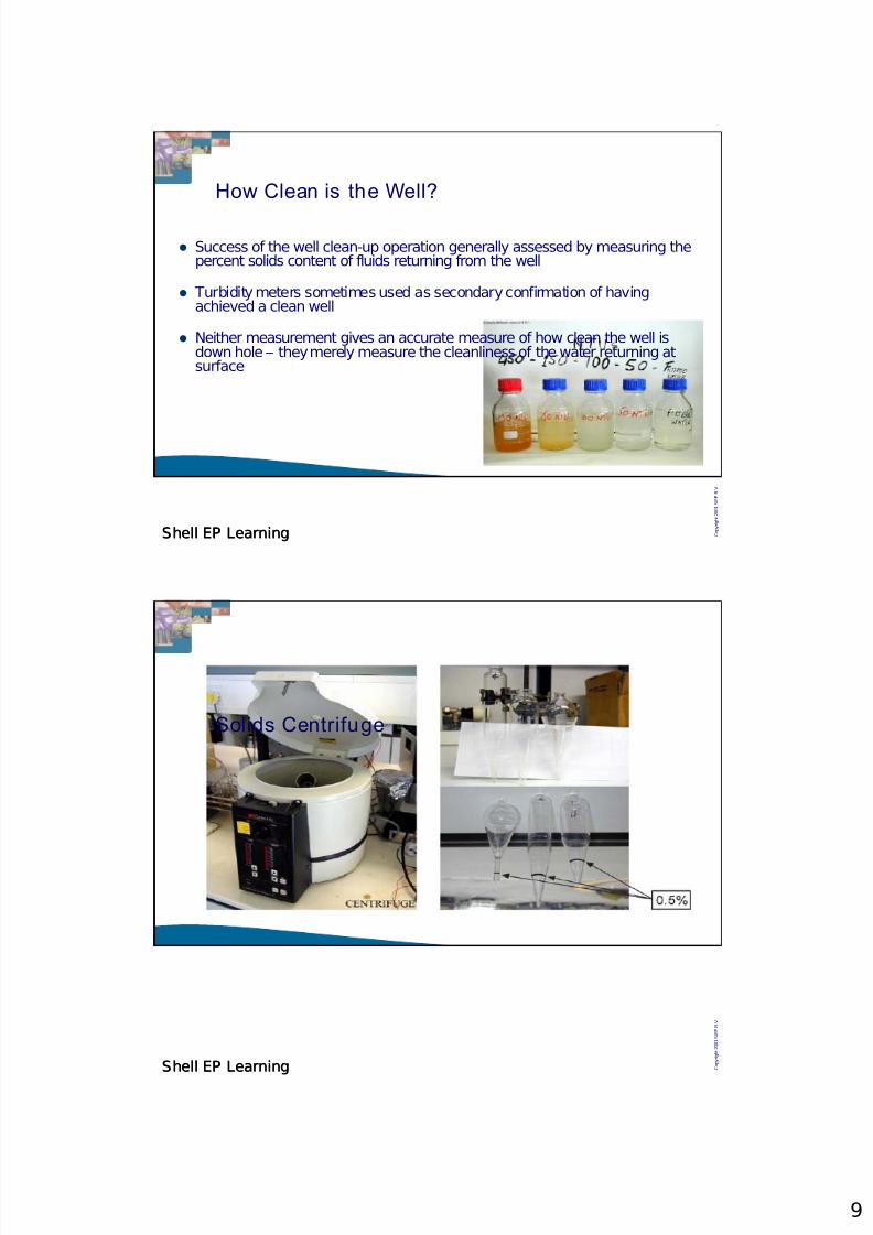
How Clean is the Well?
z Success of the well clean-up operation generally assessed by measuring thepercent solids content of fluids returning from the well
z Turbidity meters sometimes used as secondary confirmation of havingachieved a clean well
z Neither measurement gives an accurate measure of how clean the well isdown hole – they merely measure the cleanliness of the water returning atsurface
C o p y r i g h t 2 0 0 1 S I E P B . V
SShheellll EP LEP Leeaarrnniinngg
Solids Centrifuge

7/29/2019 1 - Well Clean Up
http://slidepdf.com/reader/full/1-well-clean-up 10/12
10
C o p y r i g h t 2 0 0 1 S I E P B . V
SShheellll EP LEP Leeaarrnniinngg
Filtration
z Usual technique to remove suspended solids from brines andcompletion fluids.
z Filtration technology changed considerably from the 1980's
z increased awareness of the importance of both the content andsize distribution of suspended solids in workover and completionfluids led to the introduction of more sophisticated filtrationequipment.
z In preparation for brine filtration it is of paramount importancethat all-surface and subsurface equipment (tanks, lines, pumpsand downhole tubulars) are scrupulously cleaned to preventbrine contamination.
C o p y r i g h t 2 0 0 1 S I E P B . V
SShheellll EP LEP Leeaarrnniinngg
Filtration Systems

7/29/2019 1 - Well Clean Up
http://slidepdf.com/reader/full/1-well-clean-up 11/12
11
C o p y r i g h t 2 0 0 1 S I E P B . V
SShheellll EP LEP Leeaarrnniinngg
Filter Cartr idges
C o p y r i g h t 2 0 0 1 S I E P B . V
SShheellll EP LEP Leeaarrnniinngg
DE Filtration Unit
7/29/2019 1 - Well Clean Up
http://slidepdf.com/reader/full/1-well-clean-up 12/12
C o p y r i g h t 2 0 0 1 S I E P B . V
SShheellll EP LEP Leeaarrnniinngg
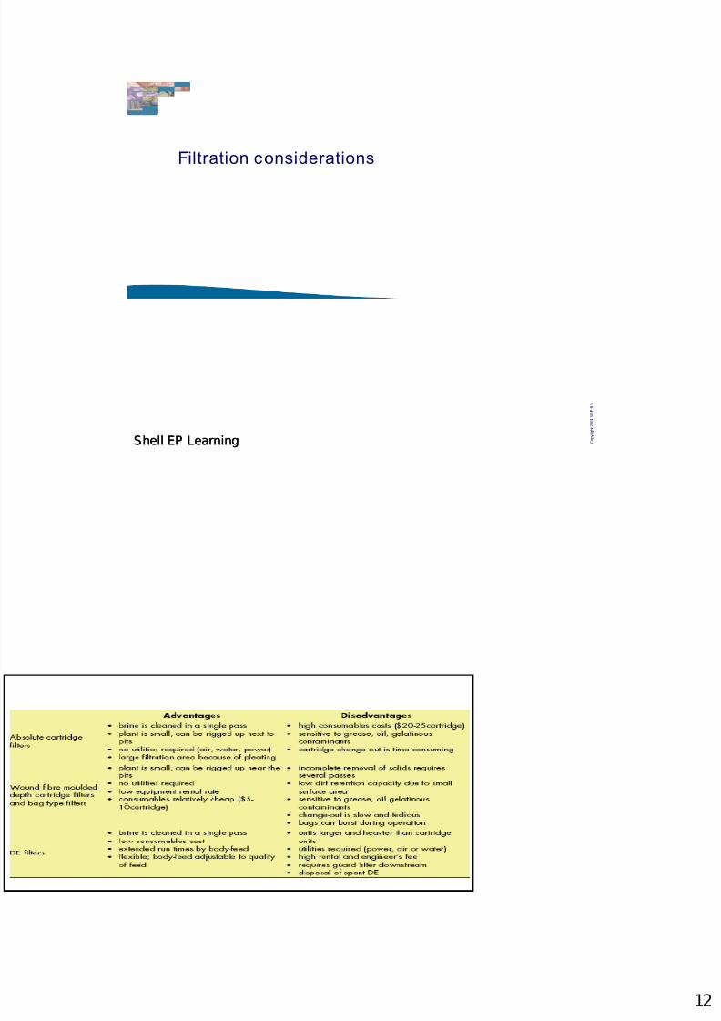
Filtration considerations