1 UTC-N Overview of Campus NetworksDesign. 2 Overview n Read Chapter 1 for further information and...
53
1 UTC-N Overview of Campus Networks Overview of Campus Networks Design Design
-
Upload
kolton-grill -
Category
Documents
-
view
214 -
download
0
Transcript of 1 UTC-N Overview of Campus NetworksDesign. 2 Overview n Read Chapter 1 for further information and...
1
UTC-N
Overview of Campus NetworksOverview of Campus Networks DesignDesign
2
Overview Read Chapter 1 for further information and
explanations Much of the information in this chapter will
become clearer throughout the semester as this chapter is meant to introduce you to some of the topics we will be discussing later.
The design models used in this chapter is not a template for network design. It should be used as a foundation for discussion of concepts and a vehicle for addressing various issues.
3
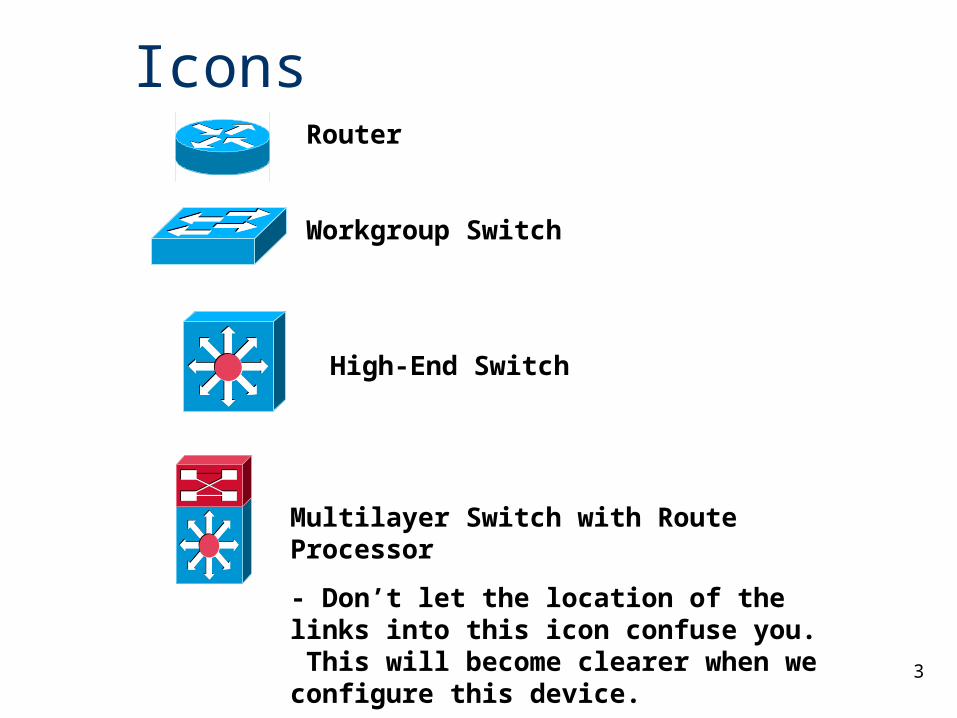
Icons
Multilayer Switch with Route Processor
- Don’t let the location of the links into this icon confuse you. This will become clearer when we configure this device.
High-End Switch
Router
Workgroup Switch
4
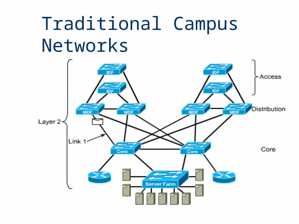
Traditional Campus Networks
5
Traditional Campus Networks
Campus Network A building or group of buildings connected into one
enterprise network that consists of or more LANs. The company usually owns the physical wires
deployed in the campus. Generally uses LAN technologies. Generally deploy a campus design that is optimized
for the fastest functional architecture over existing wire.
6
Traditional Campus NetworksNetwork Administrator Challenges LAN run effectively and efficiently Availability and performance impacted by the amount of
bandwidth in the network Understand, implement and manage traffic flow
Current Issues Broadcasts: IP ARP requests
Emerging Issues Multicast traffic (traffic propagated to a specific group of
users on a subnet), video conferencing, multimedia traffic Security and traffic flow
7
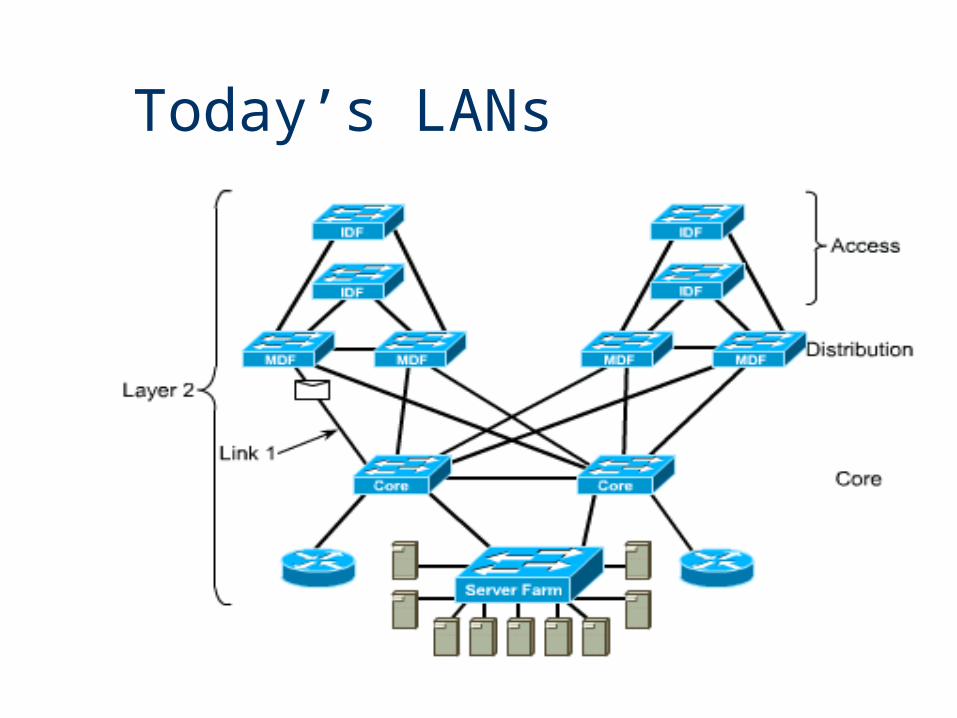
Today’s LANs
8
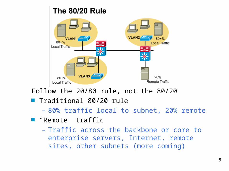
Follow the 20/80 rule, not the 80/20 Traditional 80/20 rule
– 80% traffic local to subnet, 20% remote “Remote” traffic
– Traffic across the backbone or core to enterprise servers, Internet, remote sites, other subnets (more coming)
9
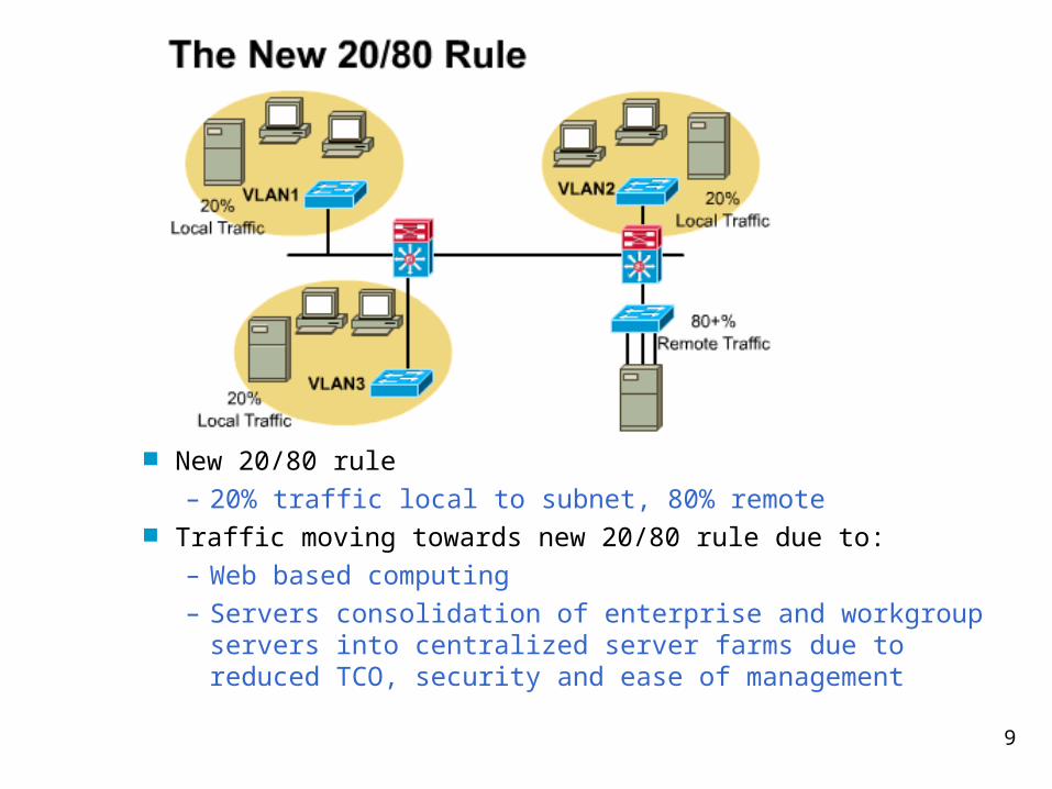
New 20/80 rule– 20% traffic local to subnet, 80% remote
Traffic moving towards new 20/80 rule due to:– Web based computing– Servers consolidation of enterprise and workgroup servers into
centralized server farms due to reduced TCO, security and ease of management
10
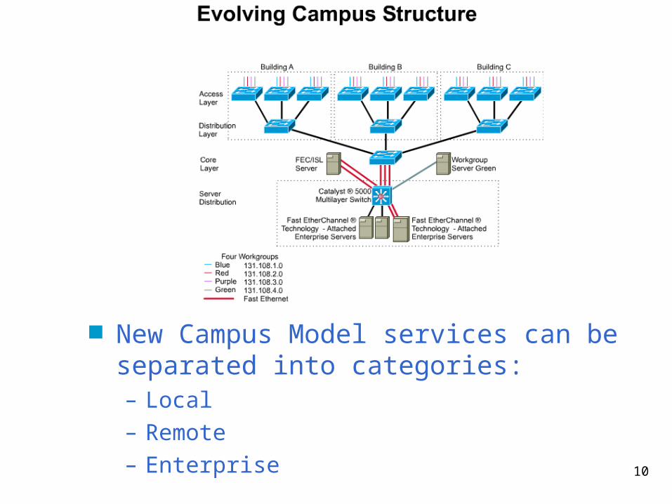
New Campus Model services can be separated into categories:– Local– Remote– Enterprise
11
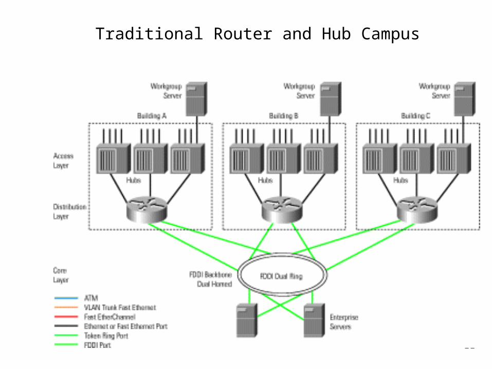
Traditional Router and Hub Campus
12
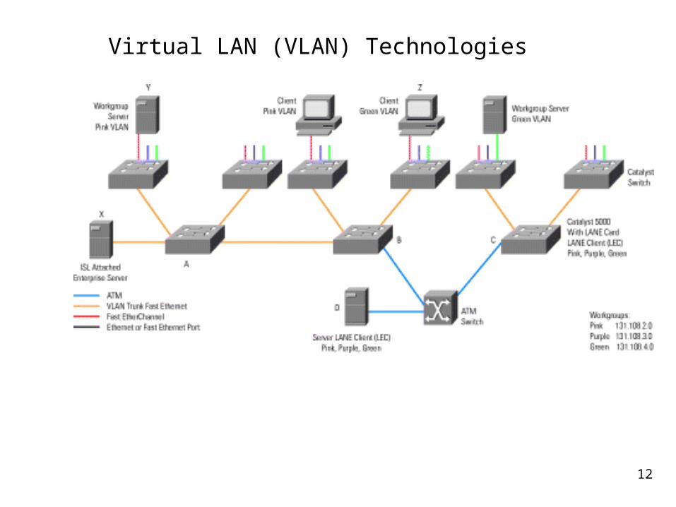
Virtual LAN (VLAN) Technologies
13
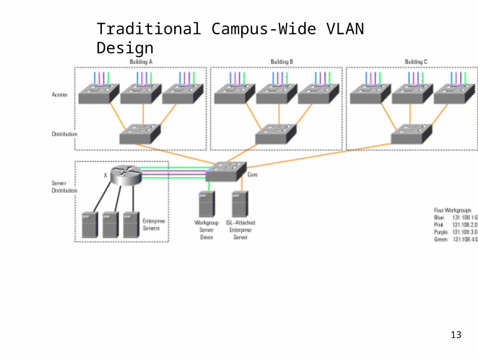
Traditional Campus-Wide VLAN Design
14
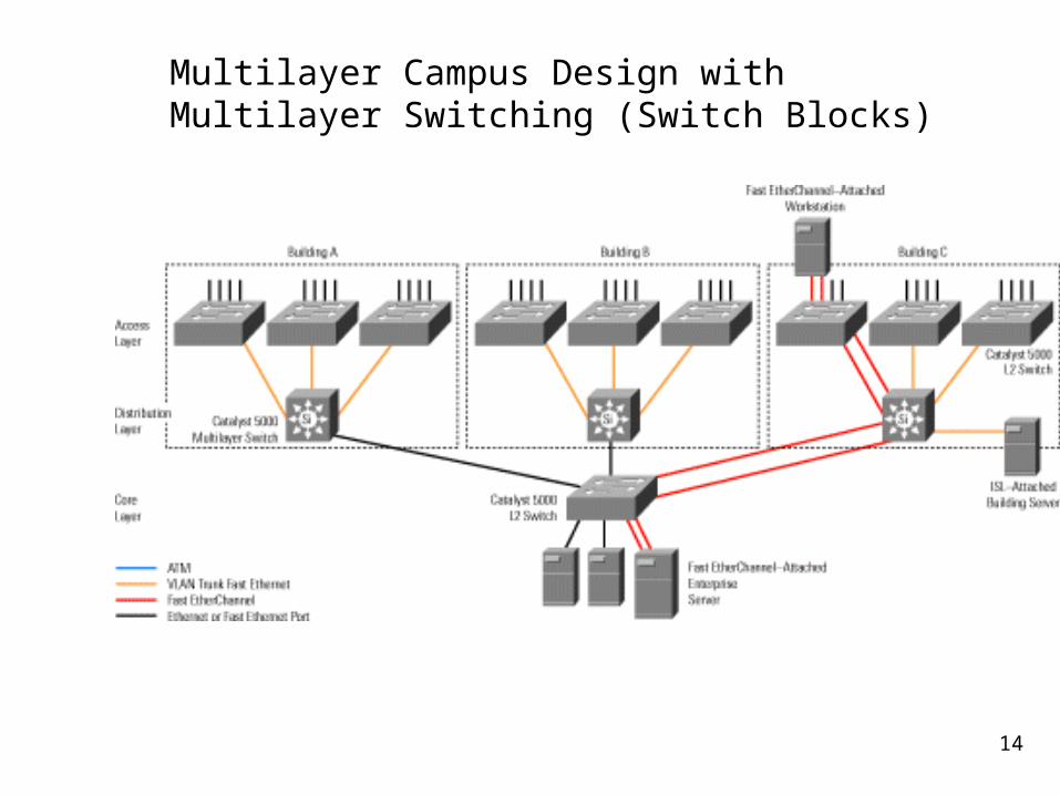
Multilayer Campus Design with Multilayer Switching (Switch Blocks)
15
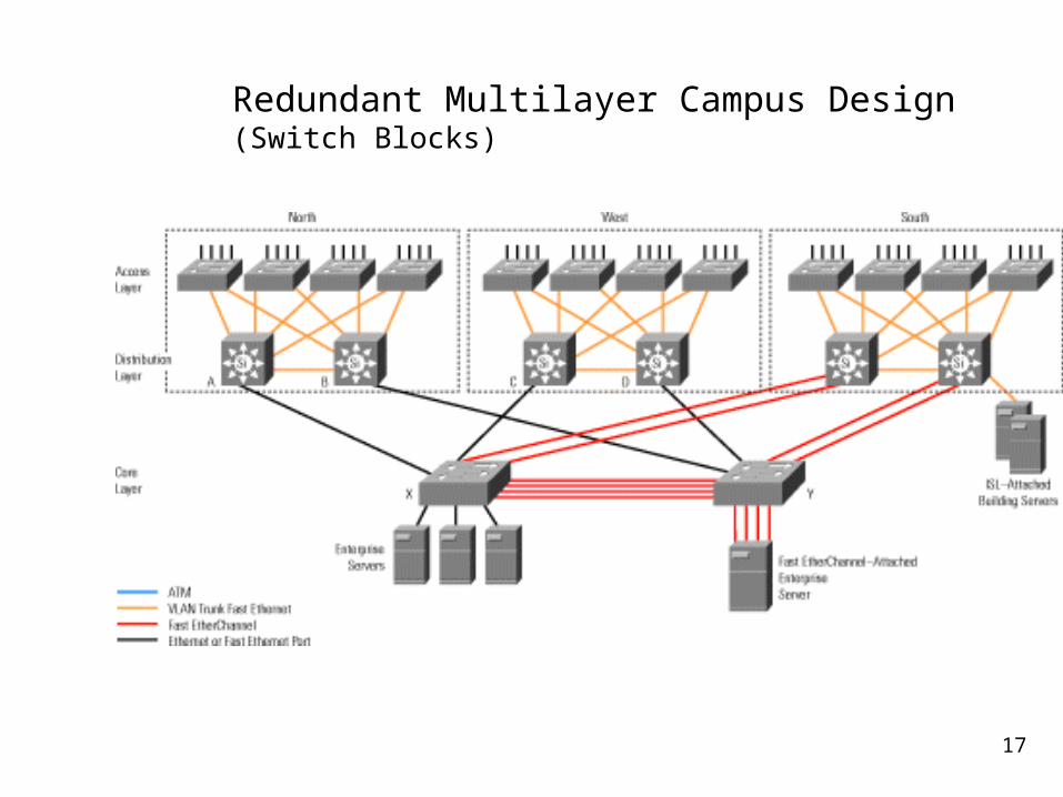
(FYI: Review) Because Layer 3 switching is used in the distribution layer of the multilayer model, this is where many of the characteristic advantages of routing apply. The distribution layer forms a broadcast boundary so that broadcasts don't pass from a building to the backbone or vice-versa. Value-added features of the Cisco IOS software apply at the distribution layer. For example, the distribution-layer switches cache information about Novell servers and respond to Get Nearest Server queries from Novell clients in the building. Another example is forwarding Dynamic Host Configuration Protocol (DHCP)
messages from mobile IP workstations to a DHCP server.
16
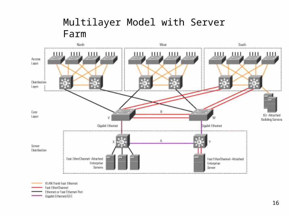
Multilayer Model with Server Farm
17
Redundant Multilayer Campus Design (Switch Blocks)
18
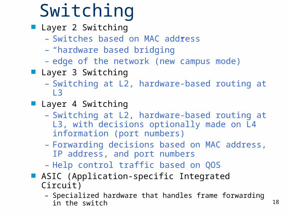
Switching Layer 2 Switching
– Switches based on MAC address– “hardware based bridging”– edge of the network (new campus mode)
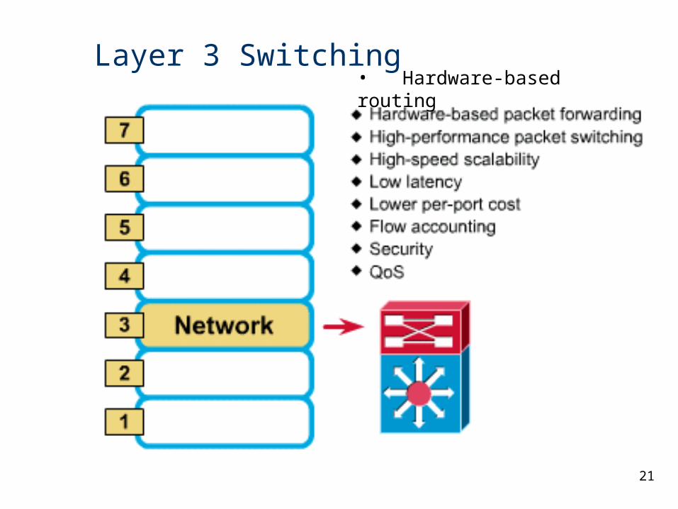
Layer 3 Switching– Switching at L2, hardware-based routing at L3
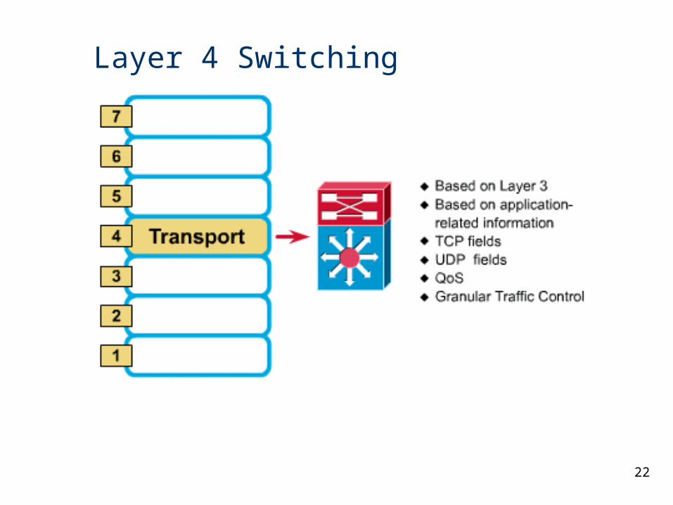
Layer 4 Switching– Switching at L2, hardware-based routing at L3,
with decisions optionally made on L4 information (port numbers)
– Forwarding decisions based on MAC address, IP address, and port numbers
– Help control traffic based on QOS ASIC (Application-specific Integrated Circuit)
– Specialized hardware that handles frame forwarding in the switch
19
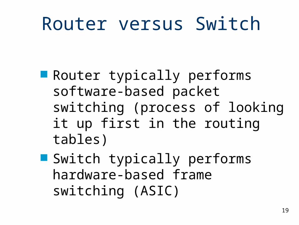
Router versus Switch
Router typically performs software-based packet switching (process of looking it up first in the routing tables)
Switch typically performs hardware-based frame switching (ASIC)
20
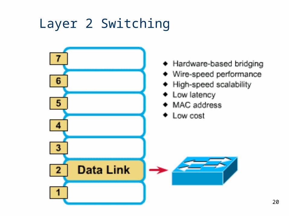
Layer 2 Switching
21
Layer 3 Switching• Hardware-based routing
22
Layer 4 Switching
23
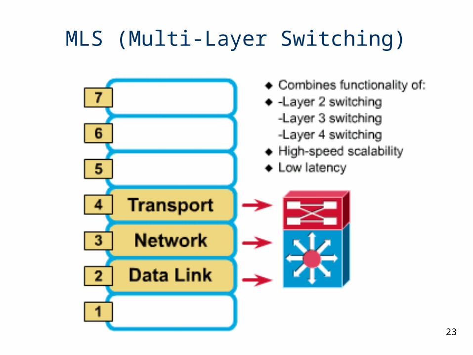
MLS (Multi-Layer Switching)
24
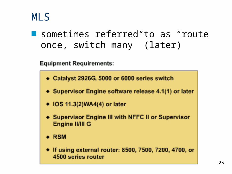
MLS Cisco’ specialized form of switching and
routing, not generic L3 routing/L2 switching
Multilayer Switches can operate at Layers 2, 3, and 4
cannot be performed using our CCNP lab equipment (Catalyst 4006 switches and 2620 routers)
“route once, switch many”
25
MLS
sometimes referred to as “route once, switch many” (later)
26
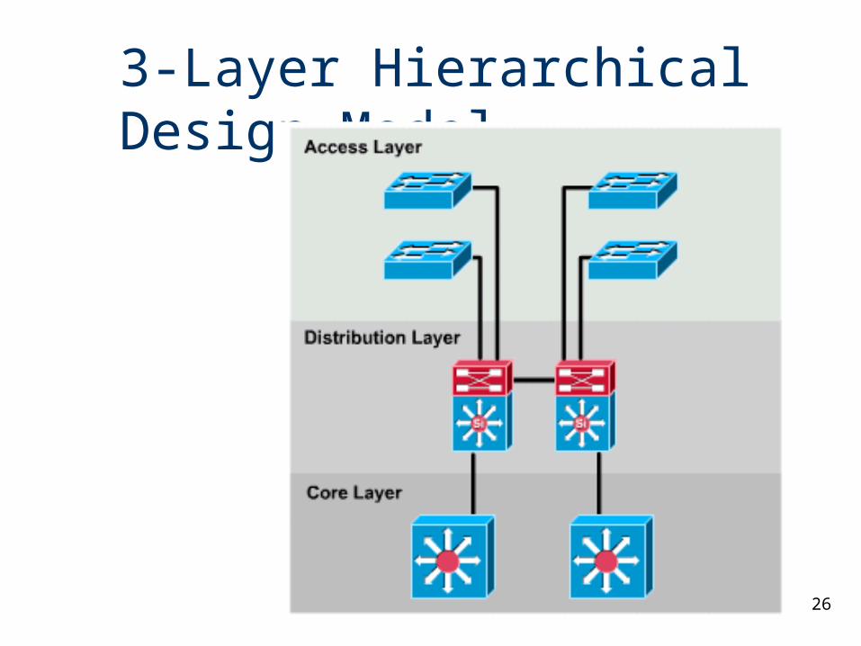
3-Layer Hierarchical Design Model
27
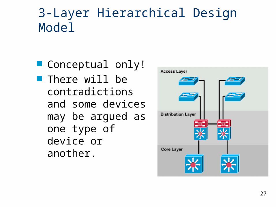
3-Layer Hierarchical Design Model
Conceptual only! There will be
contradictions and some devices may be argued as one type of device or another.
28
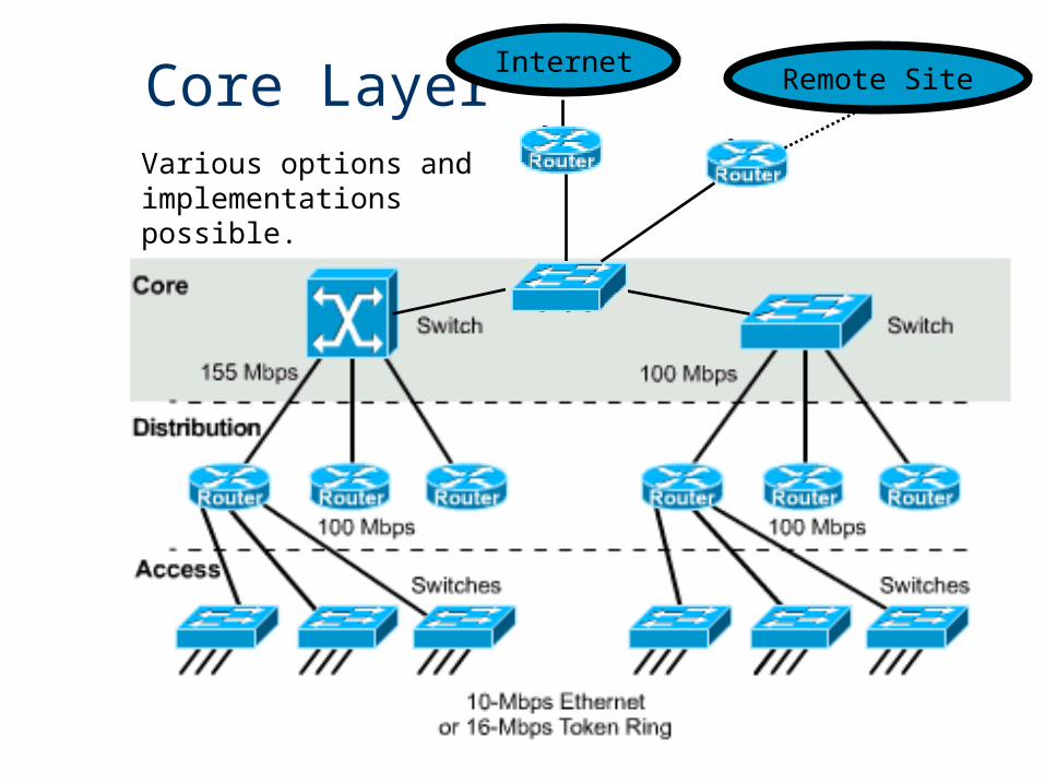
Core LayerInternet
Remote Site
Various options and implementations possible.
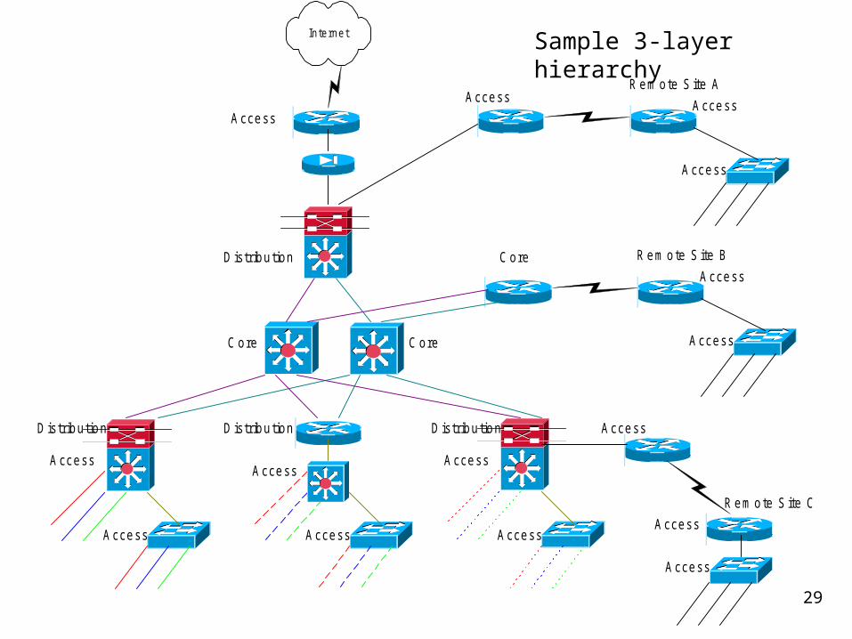
29
Sample 3-layer hierarchyIn ternet
C ore
C oreC ore
D istribu tion D istribu tion D istribu tion
A ccessA ccess
A ccess
A ccess A ccess A ccess
A ccess
A ccess
A ccess
A ccess
A ccess
R em ote S ite B
R em ote S ite C
A ccess
D istribu tion
A ccess
A ccess
R em ote S ite AA ccess
30
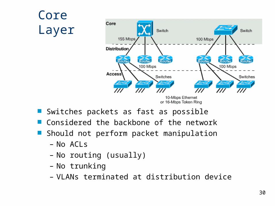
Core Layer
Switches packets as fast as possible Considered the backbone of the network Should not perform packet manipulation
– No ACLs
– No routing (usually)
– No trunking
– VLANs terminated at distribution device
31
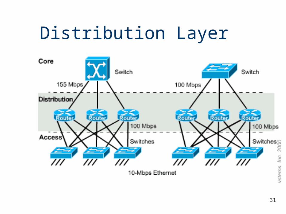
Distribution Layer
32
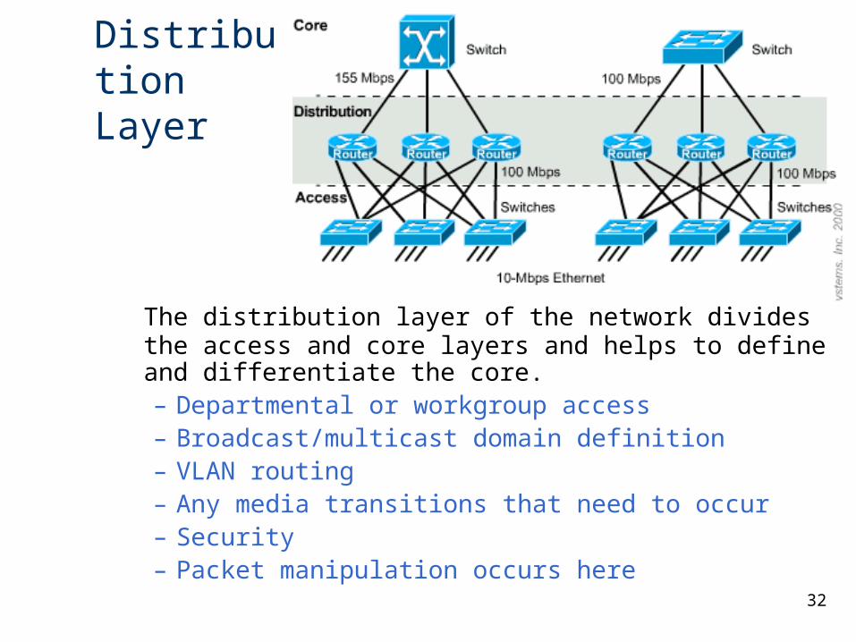
Distribution Layer
The distribution layer of the network divides the access and core layers and helps to define and differentiate the core. – Departmental or workgroup access – Broadcast/multicast domain definition – VLAN routing – Any media transitions that need to occur – Security – Packet manipulation occurs here
33
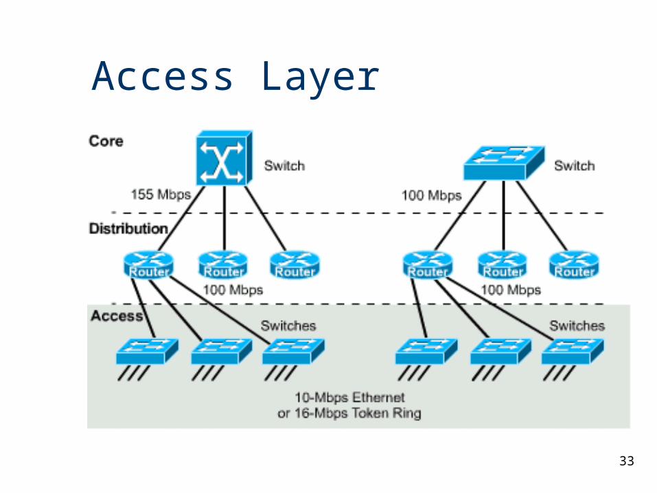
Access Layer
34
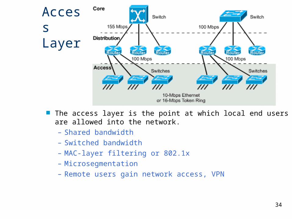
Access Layer
The access layer is the point at which local end users are allowed into the network. – Shared bandwidth – Switched bandwidth – MAC-layer filtering or 802.1x – Microsegmentation– Remote users gain network access, VPN
35
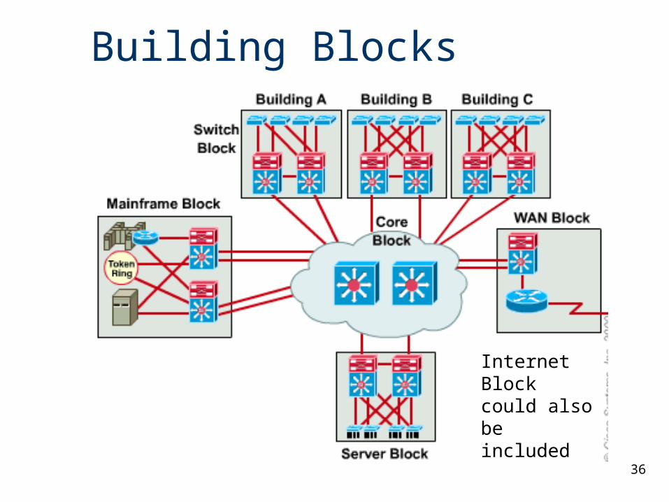
Building Blocks
Network building blocks can be any one of the following fundamental campus elements:– Switch block – Core block
Contributing variables– Server block – WAN block – Mainframe block – Internet connectivity
36
Building Blocks
Internet Block could also be included
37
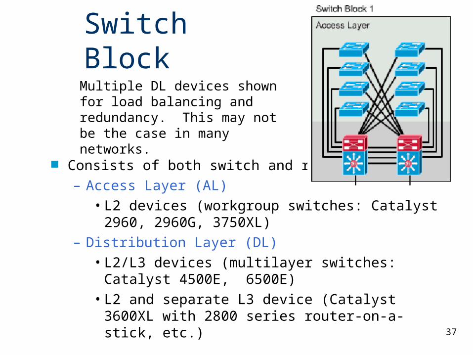
Switch Block
Consists of both switch and router functions. – Access Layer (AL)
• L2 devices (workgroup switches: Catalyst 2960, 2960G, 3750XL)
– Distribution Layer (DL)• L2/L3 devices (multilayer switches: Catalyst
4500E, 6500E)• L2 and separate L3 device (Catalyst 3600XL
with 2800 series router-on-a-stick, etc.)
Multiple DL devices shown for load balancing and redundancy. This may not be the case in many networks.
38
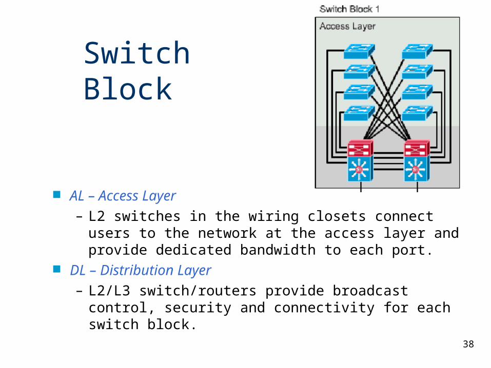
AL – Access Layer– L2 switches in the wiring closets connect users to
the network at the access layer and provide dedicated bandwidth to each port.
DL – Distribution Layer– L2/L3 switch/routers provide broadcast control,
security and connectivity for each switch block.
Switch Block
39
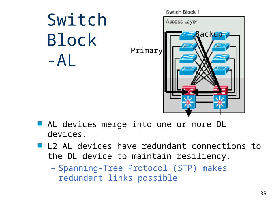
AL devices merge into one or more DL devices. L2 AL devices have redundant connections to the DL
device to maintain resiliency.– Spanning-Tree Protocol (STP) makes redundant
links possible
Switch Block-AL Primary
Backup
40
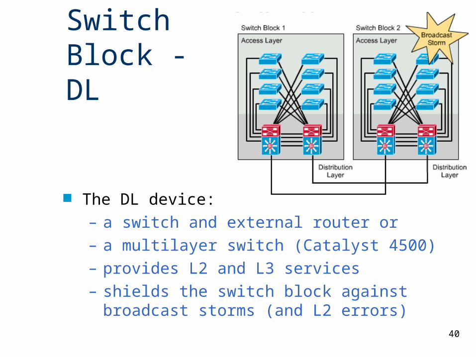
Switch Block - DL
The DL device:– a switch and external router or– a multilayer switch (Catalyst 4500)– provides L2 and L3 services– shields the switch block against broadcast storms
(and L2 errors)
41
Sizing the Switch Block
42
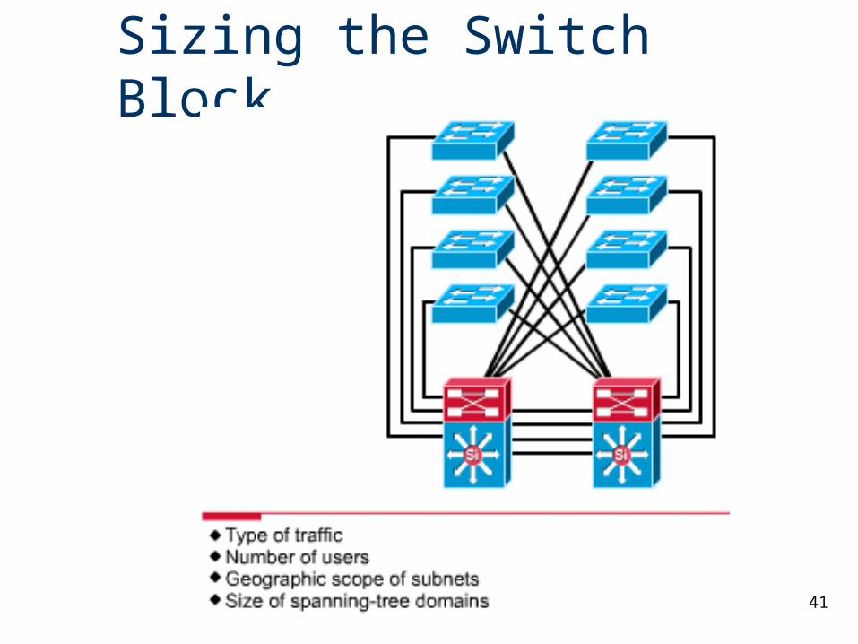
Sizing the Switch Block
A switch block is too large if: – A traffic bottleneck occurs in the routers at
the distribution layer because of intensive CPU processing resulting from policy-based filters
– Broadcast or multicast traffic slows down the switches and routers
43
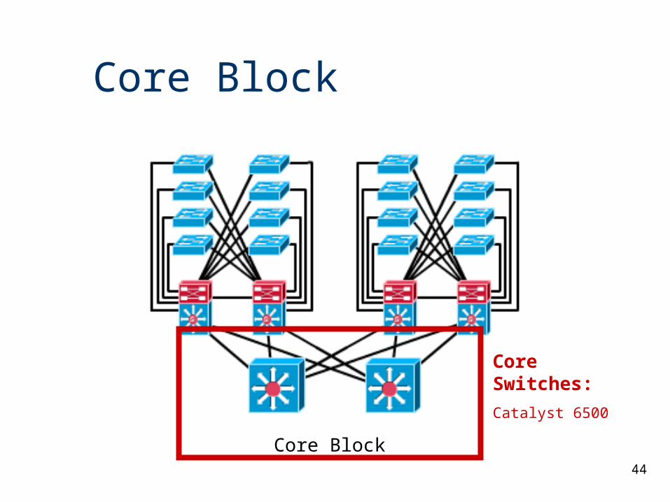
Core Block A core is required when there are two or more switch
blocks, otherwise the core or backbone is between the distribution switch and the perimeter router.
The core block is responsible for transferring cross-campus traffic without any processor-intensive operations.
All the traffic going to and from the switch blocks, server blocks, the Internet, and the wide-area network must pass through the core.
44
Core Block
Core Switches:
Catalyst 6500
Core Block
45
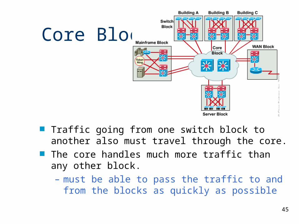
Core Block
Traffic going from one switch block to another also must travel through the core.
The core handles much more traffic than any other block.– must be able to pass the traffic to and from the
blocks as quickly as possible
46
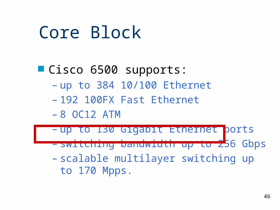
Core Block
Cisco 6500 supports:– up to 384 10/100 Ethernet– 192 100FX Fast Ethernet– 8 OC12 ATM– up to 130 Gigabit Ethernet ports– switching bandwidth up to 256 Gbps– scalable multilayer switching up to 170
Mpps.
47
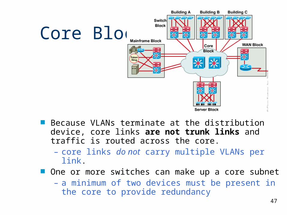
Core Block
Because VLANs terminate at the distribution device, core links are not trunk links and traffic is routed across the core. – core links do not carry multiple VLANs per link.
One or more switches can make up a core subnet– a minimum of two devices must be present in the
core to provide redundancy
48
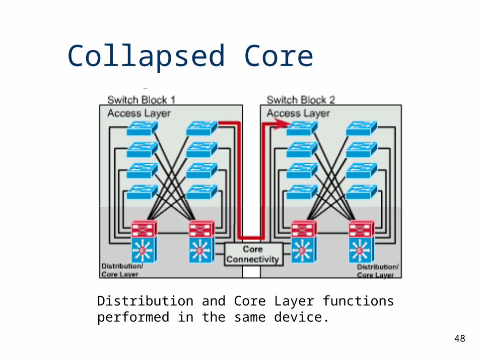
Collapsed Core
Distribution and Core Layer functions performed in the same device.
49
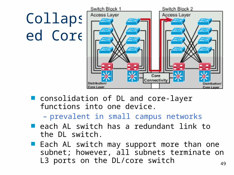
Collapsed Core
consolidation of DL and core-layer functions into one device. – prevalent in small campus networks
each AL switch has a redundant link to the DL switch. Each AL switch may support more than one subnet;
however, all subnets terminate on L3 ports on the DL/core switch
50
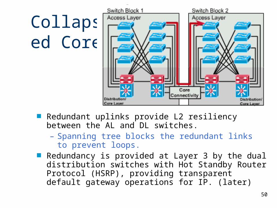
Redundant uplinks provide L2 resiliency between the AL and DL switches. – Spanning tree blocks the redundant links to prevent
loops. Redundancy is provided at Layer 3 by the dual distribution
switches with Hot Standby Router Protocol (HSRP), providing transparent default gateway operations for IP. (later)
Collapsed Core
51
Dual Core
52
Dual Core
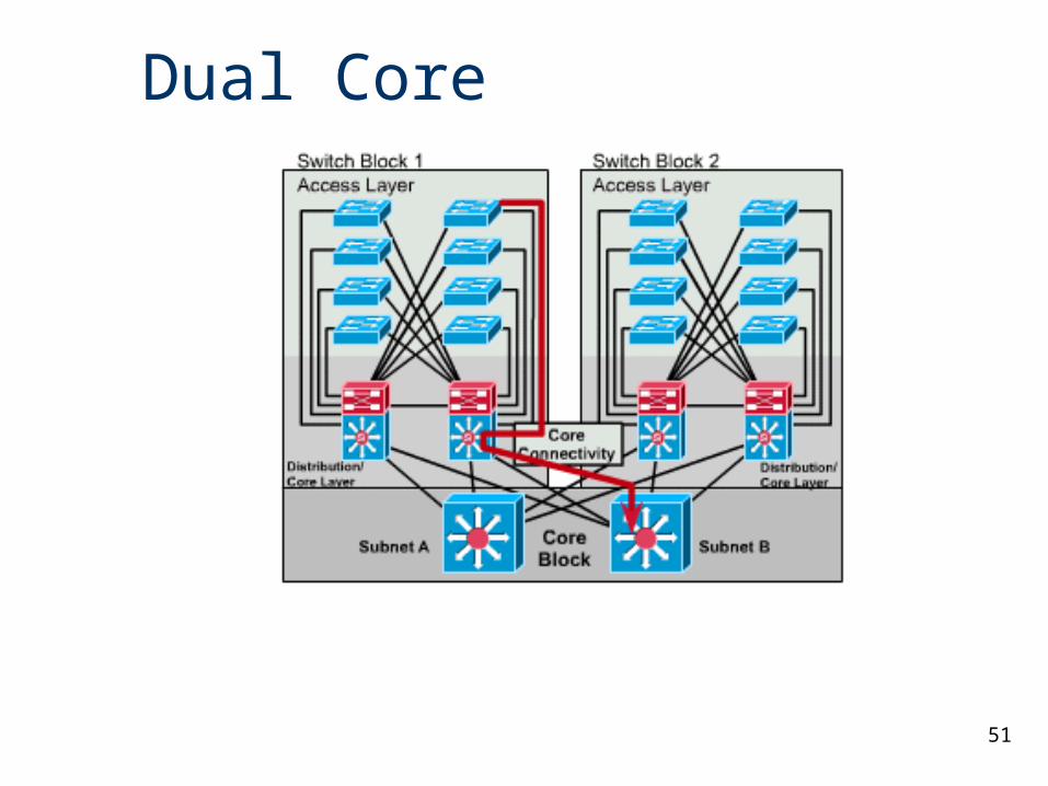
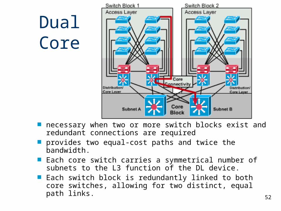
necessary when two or more switch blocks exist and redundant connections are required
provides two equal-cost paths and twice the bandwidth. Each core switch carries a symmetrical number of
subnets to the L3 function of the DL device. Each switch block is redundantly linked to both core
switches, allowing for two distinct, equal path links.
53
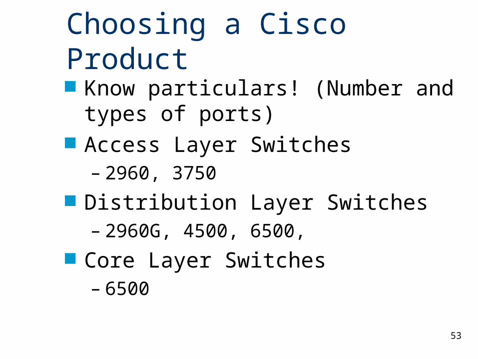
Choosing a Cisco Product Know particulars! (Number and types of
ports) Access Layer Switches
– 2960, 3750 Distribution Layer Switches
– 2960G, 4500, 6500, Core Layer Switches
– 6500