1 UML--definition UML: stands for "unified modeling language” unifies methods of Booch, Rumbaugh...
40
1 UML-- definition UML: stands for "unified modeling language” unifies methods of Booch, Rumbaugh (OMT or Object Modeling Technique), and Jacobson (OOSE or Object-Oriented Software Engineering) mainly a modeling language, not a complete development method Early versions -- second half of the 90's Not all methods we will use are officially part of the UML description
-
Upload
lambert-willis -
Category
Documents
-
view
226 -
download
3
Transcript of 1 UML--definition UML: stands for "unified modeling language” unifies methods of Booch, Rumbaugh...
1
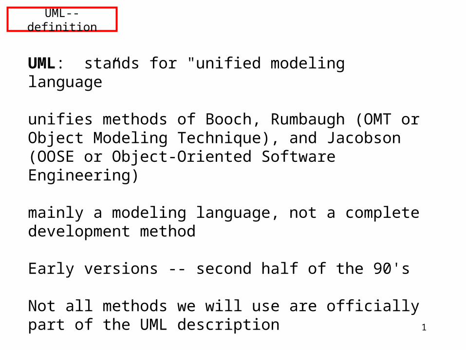
UML--definition
UML: stands for "unified modeling language”
unifies methods of Booch, Rumbaugh (OMT or Object Modeling Technique), and Jacobson (OOSE or Object-Oriented Software Engineering)
mainly a modeling language, not a complete development method
Early versions -- second half of the 90's
Not all methods we will use are officially part of the UML description
2
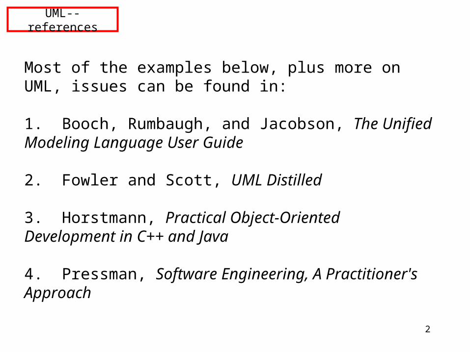
UML--references
Most of the examples below, plus more on UML, issues can be found in:
1. Booch, Rumbaugh, and Jacobson, The Unified Modeling Language User Guide
2. Fowler and Scott, UML Distilled
3. Horstmann, Practical Object-Oriented Development in C++ and Java
4. Pressman, Software Engineering, A Practitioner's Approach
3
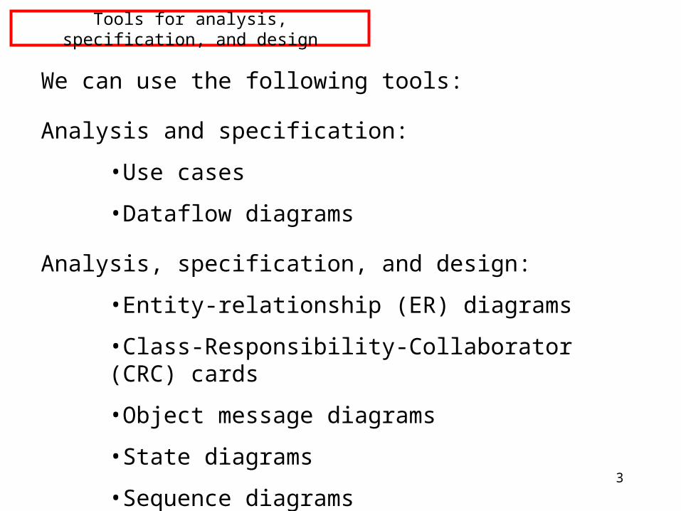
Tools for analysis, specification, and design
We can use the following tools:
Analysis and specification:
•Use cases
•Dataflow diagrams
Analysis, specification, and design:
•Entity-relationship (ER) diagrams
•Class-Responsibility-Collaborator (CRC) cards
•Object message diagrams
•State diagrams
•Sequence diagrams
4
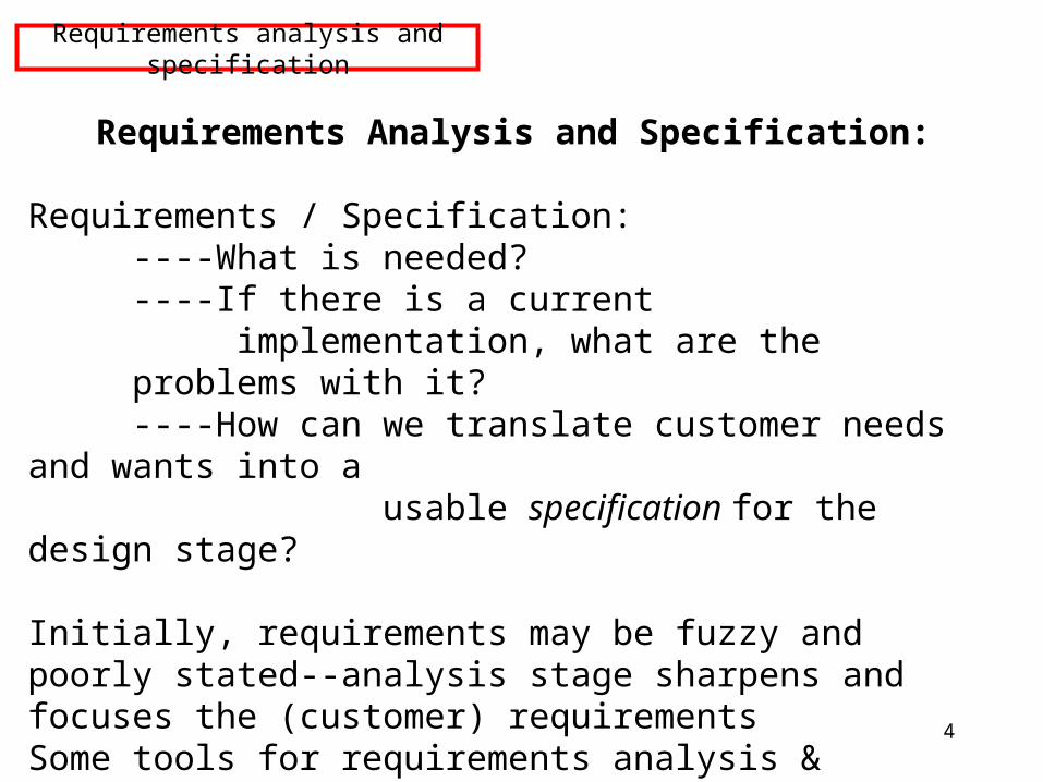
Requirements Analysis and Specification:
Requirements / Specification:----What is needed?----If there is a current implementation, what are the problems with it?----How can we translate customer needs and wants into a
usable specification for the design stage?
Initially, requirements may be fuzzy and poorly stated--analysis stage sharpens and focuses the (customer) requirementsSome tools for requirements analysis & specification:
----use cases----data flow diagrams----”user stories” (XP)
Requirements analysis and specification
5
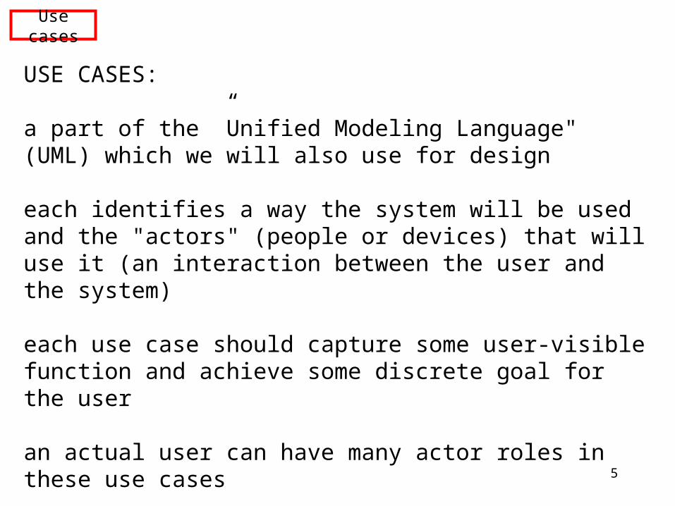
USE CASES:
a part of the ”Unified Modeling Language" (UML) which we will also use for design
each identifies a way the system will be used and the "actors" (people or devices) that will use it (an interaction between the user and the system)
each use case should capture some user-visible function and achieve some discrete goal for the user
an actual user can have many actor roles in these use cases
an instance of a use case is usually called a "scenario"
Use cases
6
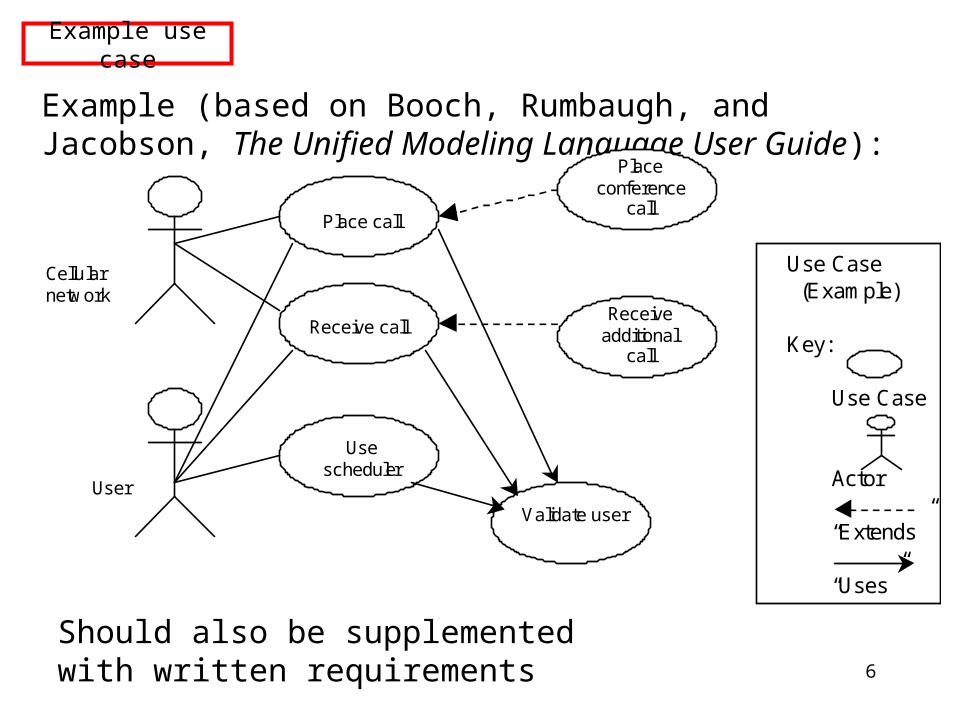
Example (based on Booch, Rumbaugh, and Jacobson, The Unified Modeling Language User Guide):
Place call
Receive call
Use scheduler
Receive additional
call
Place conference
call
Cellular network
User
Use Case (Example) Key: Use Case Actor “Extends” “Uses”
Validate user
Example use case
Should also be supplemented with written requirements
7
Data flow diagram (DFD):
----graphical technique to show information flow and transforms applied as data move from input to output
----each function or information transformer is represented by a circle or "bubble"
----data labels are placed on arrows showing information flow
----external entities (data "producers" or "consumers") are shown as square boxes
Data flow diagrams (1)
8
The data flow diagram does not describe the processing sequence; it is not a flowchart. But it can be very useful during requirements analysis for a system being developed.
A DFD can be used to provide a functional model for the system being developed, thus supplementing the class relationship, object message, and state diagram models of UML.
Functional models based on DFD's were part of the Object Modeling Technique (OMT) developed by Rumbaugh, one of the three main designers of UML.
Data flow diagrams (2)
9
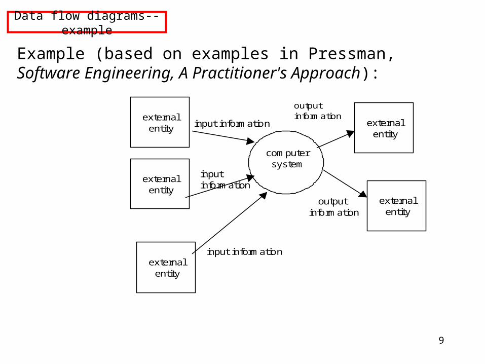
Example (based on examples in Pressman, Software Engineering, A Practitioner's Approach):
external entity
external entity
external entity
external entity
external entity
computer system
input information
input information
input information
output information
output information
Data flow diagrams--example
10
Requirements document must be as clear as possible, consistent, complete
Important parts of a requirements document (Berezin, 1999):
1. Application Overview:-- objectives-- (business process—how application fits) -- user roles and responsibilities-- interactions with other systems-- (replacement of legacy systems)-- (production rollout considerations)-- terminology
Requirements document
11
Important parts of a requirements document (continued):
2. Functional requirements:-- functionality
precise, detailed, for each user classaddress security, auditing, reporting, ability of users to modify application
-- (scope (for a multiphase project) )-- performance-- usability-- concurrency
Requirements document--continued
12
Specification:
must be as complete as possible, consistent, clear
Specification
13
Principles of specification:
1. functionality should be separate from implementation
2. model of system behavior must include both data and functional responses to external stimuli
3. interaction with other components must be specified
4. environment of operation must be defined
5. "cognitive model" should describe the system as seen by the user community; do not create a design or implementation model
6. must be tolerant of incompleteness and allow for additions
7. must allow for change
Principles of specification
14
Result of specification step: Software Requirements Specification
must include:
--complete information description
--detailed functional description
--representation of system behavior
--performance requirements
--design constraints
--appropriate validation criteria (for example, acceptance tests)
--…….
Software requirements specification
15
example candidate formats for specification:
IEEE 830-1984
Department of Defense
at the end of this process, customer and developer must conduct a Specification Review
Specification format
16
ER diagrams
Entity-relationship diagrams / class diagrams:
These diagrams represent the relationships between the classes in the system.
There are three basic types of relationship:
•inheritance ("is-a")
•aggregation ("has-a”)
•association ("uses")
These are commonly diagrammed as follows:
17
ER diagram: is-a
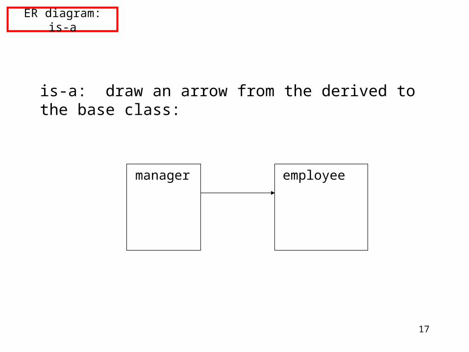
is-a: draw an arrow from the derived to the base class:
manager employee
18
ER diagram--has-a
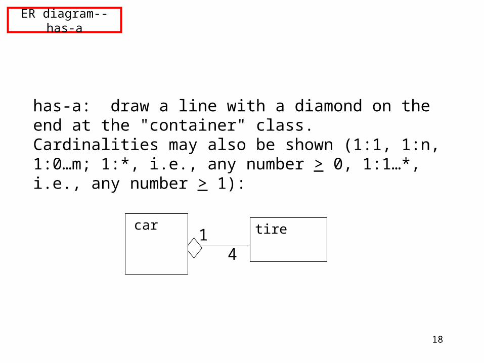
has-a: draw a line with a diamond on the end at the "container" class. Cardinalities may also be shown (1:1, 1:n, 1:0…m; 1:*, i.e., any number > 0, 1:1…*, i.e., any number > 1):
car tire1 4
19
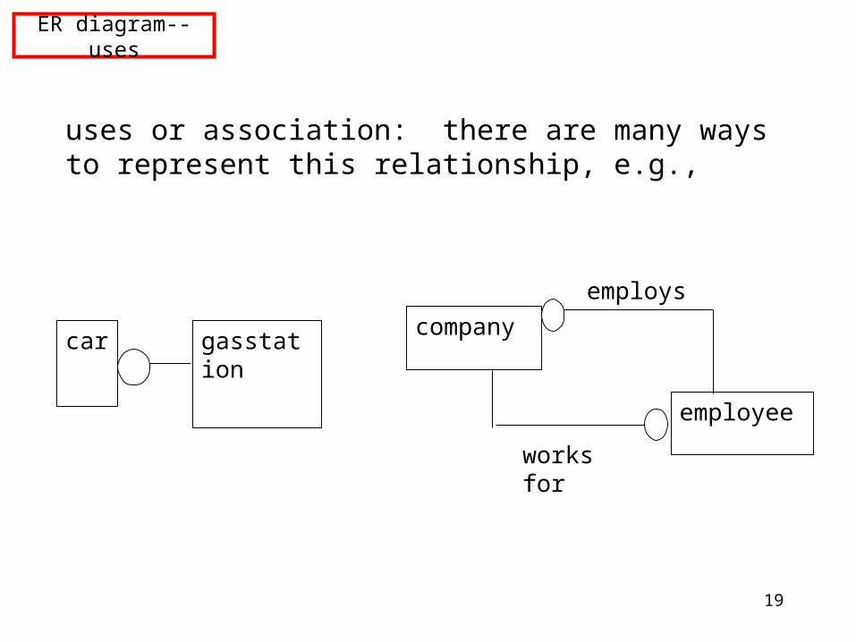
ER diagram--uses
uses or association: there are many ways to represent this relationship, e.g.,
car gasstationcompany
employee
employs
works for
20
CRC cards
CRC cards: class--responsibilities--collaborators cards
"responsibilities" = operators, methods
"collaborators" = related classes (for a particular operator or method)
Make one actual card for each discovered class, with responsibilities and collaborators on the front, data fields on the back. CRC cards are not really part of UML, but are often used in conjunction with it.
21
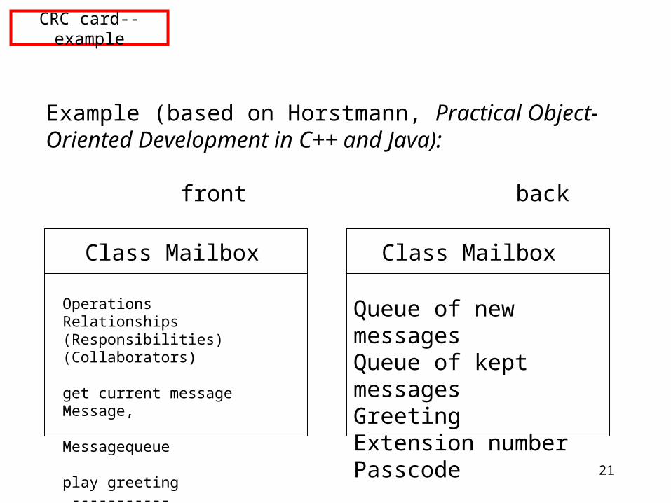
CRC card--example
Example (based on Horstmann, Practical Object-Oriented Development in C++ and Java):
front back
Class Mailbox
Operations Relationships(Responsibilities) (Collaborators)
get current message Message, Messagequeue
play greeting -----------
Queue of new messagesQueue of kept messagesGreetingExtension numberPasscode
Class Mailbox
22
Common classes
Common types of classes which the developer can look for include:
•tangible things, e.g., Mailbox, Document
•system interfaces and devices, e.g., DisplayWindow, Input Reader
•agents, e.g., Paginator, which computes document page breaks, or InputReader
•events and transactions, e.g., MouseEvent,CustomerArrival
•users and roles, e.g., Administrator, User
•systems, e.g., mailsystem (overall), InitializationSystem (initializes)
•containers, e.g., Mailbox, Invoice, Event
•foundation classes, e.g., String, Date, Vector, etc.
23
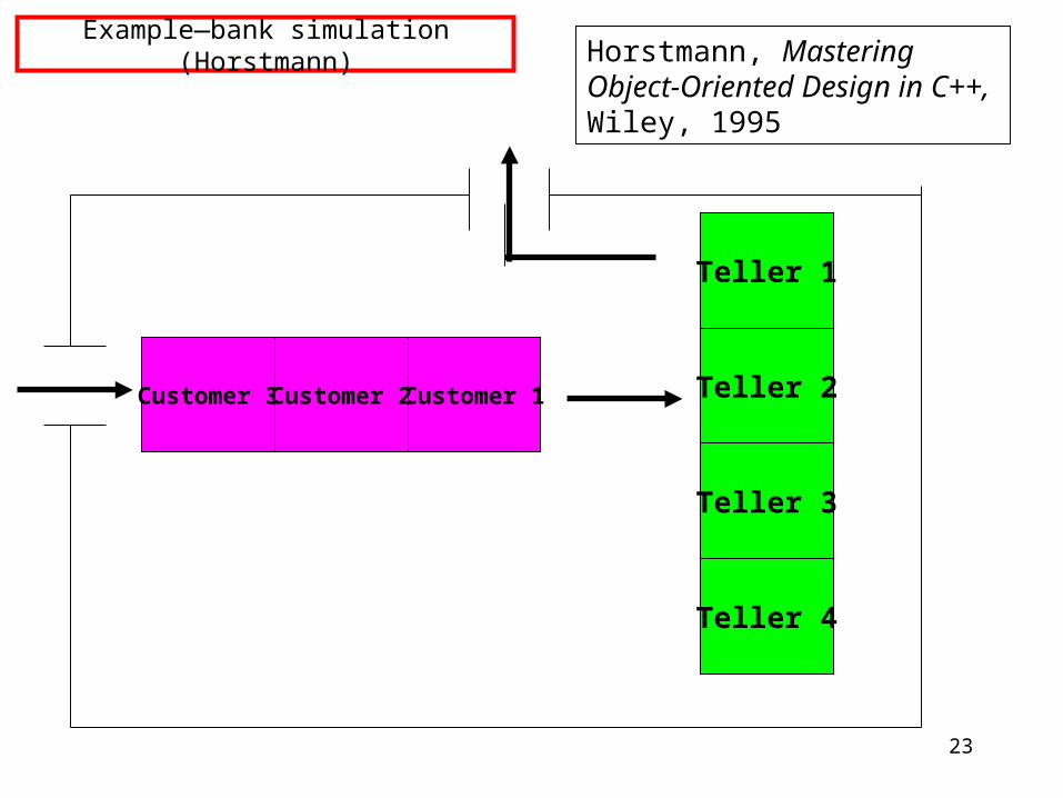
Example—bank simulation (Horstmann)
Teller 1
Teller 2
Teller 3
Teller 4
Customer 1Customer 3 Customer 2
Horstmann, Mastering Object-Oriented Design in C++, Wiley, 1995
24
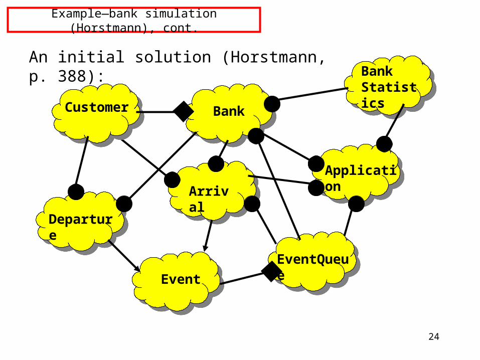
Example—bank simulation (Horstmann), cont.
An initial solution (Horstmann, p. 388):
Event
Departure
Arrival
Customer Bank
EventQueue
Application
Bank Statistics
25
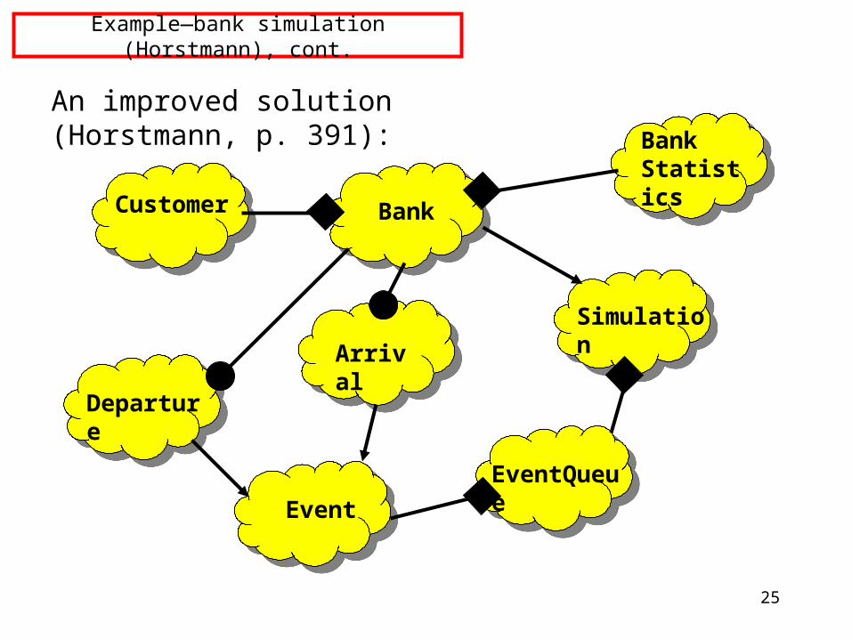
Example—bank simulation (Horstmann), cont.
An improved solution (Horstmann, p. 391):
Event
Departure
Arrival
Customer Bank
EventQueue
Simulation
Bank Statistics
26
UML Constructs to Be Covered
UML language contains many methods which will not be covered here.
(And some of the methods we are covering are not officially part of UML, although they are often used with UML, e.g., CRC cards).
What we have covered so far:
•use cases, data flow diagrams--for requirements analysis, design specification
•ER diagrams, CRC cards--for initial design
To be covered:
•collaboration or object-message diagrams, state diagrams, sequence diagrams--for more detailed design and dynamic aspects
27
Additional UML Tools We Will Use
Additional UML tools we will use:
•Collaboration or Object message diagrams
•State diagrams
•Sequence diagrams
These allow us to further refine the design, in preparation for coding.
28
Object Message Diagrams
Collaboration or Object message diagrams:
Each “responsibility” on a CRC card will be implemented as one or more functions, with information being shared by the collaborators as needed.
The collaboration or object message diagram makes each information-sharing event explicit, by showing the flow of function calls or “messages” related to that event, and gives a more precise way to check on the design being constructed.
(Not ALL functions need to be diagrammed this way, if the information-sharing mechanism is simple and obvious.)
29
Information Sharing Options
Information Sharing options:
In a collaboration or object message diagram we use a rectangle to represent each participating object (labeled by object name or by class name: object name) and we denote each function call by a labeled line or arrow from the calling object to the object responsible for carrying out the function. These calls can be sequentially numbered. These connecting lines can also be labeled to show the status of the objects carrying out the functions in question. Labels used are:
S--the object itselfF--data field of the object itselfP--procedure parameterG--global variableL--local variable
30
Information Sharing--Example--Part 1 of 3
Example:
A contrived but instructive example in Practical Object-Oriented Development in C++ and Java by Cay Horstmann (Wiley 1997) considers the case where an object of class Car must carry out the operation add_gas by accessing an object from class GasStation. This can give examples of the cases above, as follows:
31
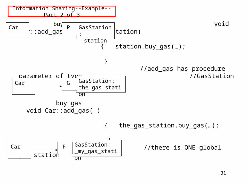
Information Sharing--Example--Part 2 of 3
buy_gas void Car::add_gas(GasStation& station) { station.buy_gas(…); }
//add_gas has procedure parameter of type //GasStation
buy_gas void Car::add_gas( ) { the_gas_station.buy_gas(…); }
//there is ONE global gas station
buy_gas void Car::add_gas( ) { _my_gas_station -> buy_gas(…); }
//car has ptr to its "own" station, a field in //the “car” object
Car GasStation:station
P
Car GasStation:_my_gas_station
F
Car GasStation:the_gas_station
G
32
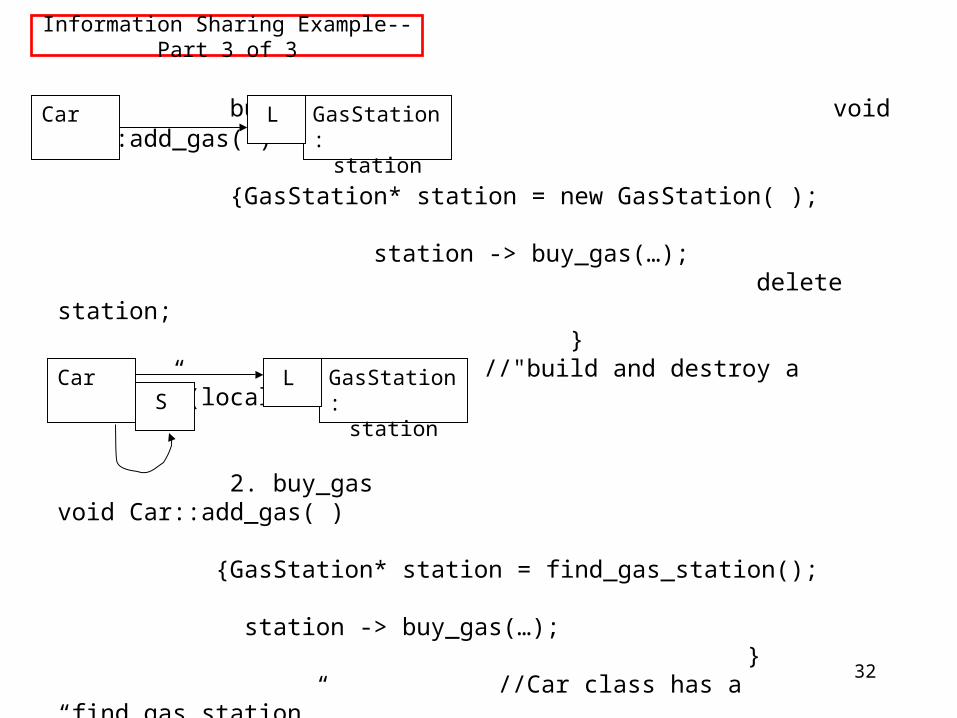
Information Sharing Example--Part 3 of 3
buy_gas void Car::add_gas( ) {GasStation* station = new GasStation( ); station -> buy_gas(…); delete station;
} //"build and destroy a station” (local variable)
2. buy_gas void Car::add_gas( ) {GasStation* station = find_gas_station(); station -> buy_gas(…); }
//Car class has a “find_gas_station” 1.find_gas_station //operation which it must ask itself to
//carry out; the return value, of type //GasStation, is a local variable
Car GasStation:station
L
Car GasStation:station
L S
33
Information Sharing--Another Example--Part 1 of 2
Here is another example, also taken from Horstmann, which is more realistic. This diagram shows the messages necessary to execute the "process_dialing" operation in a mail system. Note that "receive_message" can be carried out in two ways, depending on whether the message is for the administrator or for a general reader. The steps to be carried out are:1. Read input2a. If input is 9999, have administrator mailbox receive message.2b1. If input is another extension, find the mailbox for that extension.2b2. Have that mailbox receive a message.
34
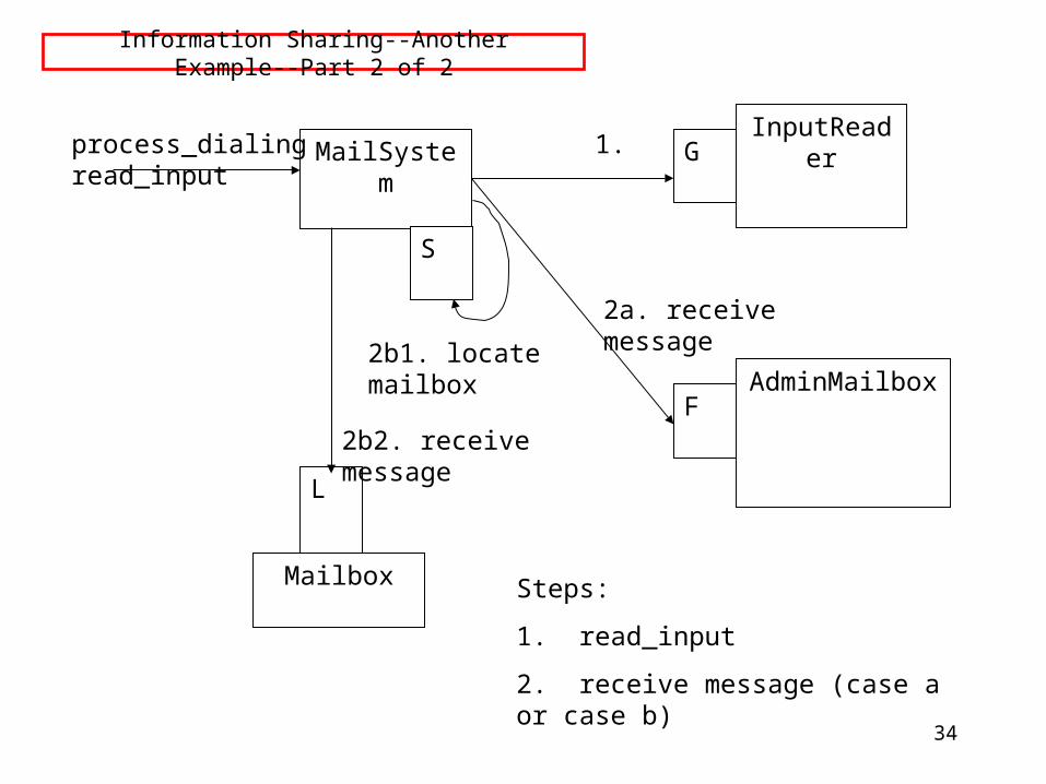
Information Sharing--Another Example--Part 2 of 2
MailSystem
Mailbox
AdminMailbox
InputReader
S
F
G
L
process_dialing 1. read_input
2b2. receive message
2b1. locate mailbox
2a. receive message
Steps:
1. read_input
2. receive message (case a or case b)
35
State Diagram
State Diagram:
another way of adding detail to the design--models dynamic behavior
describes all the possible states a particular object can be in and how that object's state changes as a result of events that affect that object
usually drawn for a single class to show behavior of a single object
used to clarify dynamic behavior within the system, as needed
36
State Diagram--Properties
A state diagram contains a "start" point, states, and transitions from one state to another.
Each state is labeled by its name and by the activities which occur when in that state.
Transitions can have three optional labels: Event [Guard] / Action.
A transition is triggered by an Event.
If there is no Event, then the transition is triggered as soon as the state activities are completed.
A Guard can be true or false. If the Guard is false, the transition is not taken.
An Action is completed during the transition.
37
State Diagram--Example
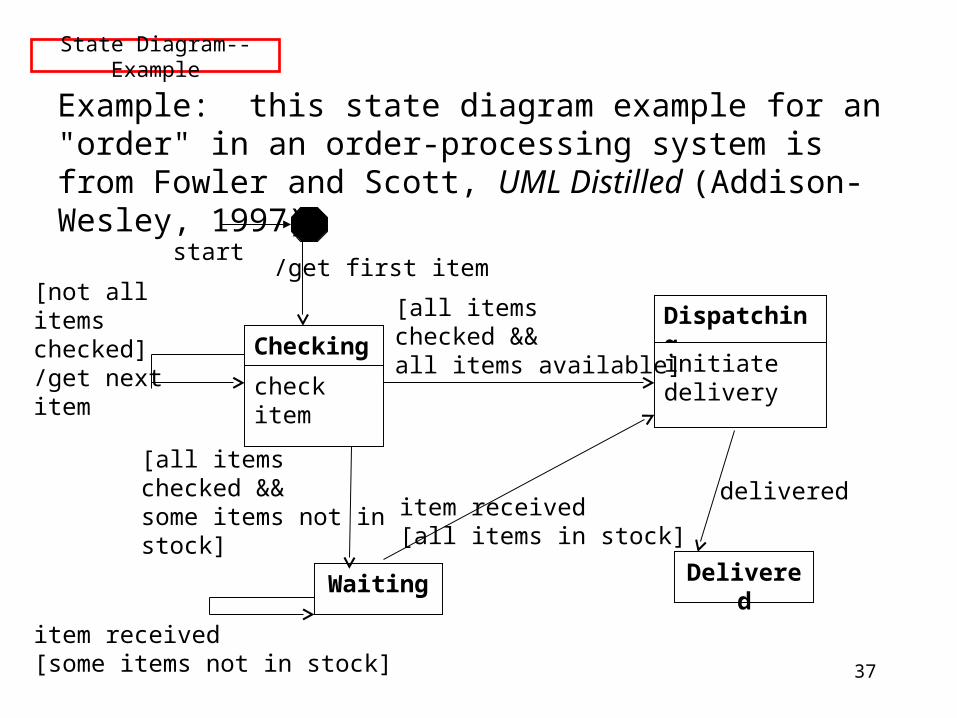
Example: this state diagram example for an "order" in an order-processing system is from Fowler and Scott, UML Distilled (Addison-Wesley, 1997):
Checking
check item
Dispatching
initiate delivery
Waiting Delivered
start/get first item
[not all items checked]/get next item
[all items checked && all items available]
[all items checked && some items not instock]
item received[some items not in stock]
item received[all items in stock]
delivered
38
Sequence Diagram
Sequence Diagram:
a sequence diagram also models dynamic behavior
typically a sequence diagram shows how objects act together to implement a single use case
messages passed between the objects are also shown
sequence diagrams help to show the overall flow of control in the part of the program being modeled
they can also be used to show:concurrent processesasynchronous behavior
39
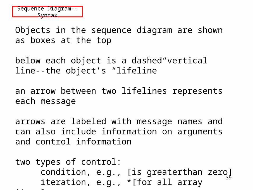
Sequence Diagram--Syntax
Objects in the sequence diagram are shown as boxes at the top
below each object is a dashed vertical line--the object’s “lifeline”
an arrow between two lifelines represents each message
arrows are labeled with message names and can also include information on arguments and control information
two types of control:condition, e.g., [is greaterthan zero]iteration, e.g., *[for all array items]
“return” arrows can also be included
40
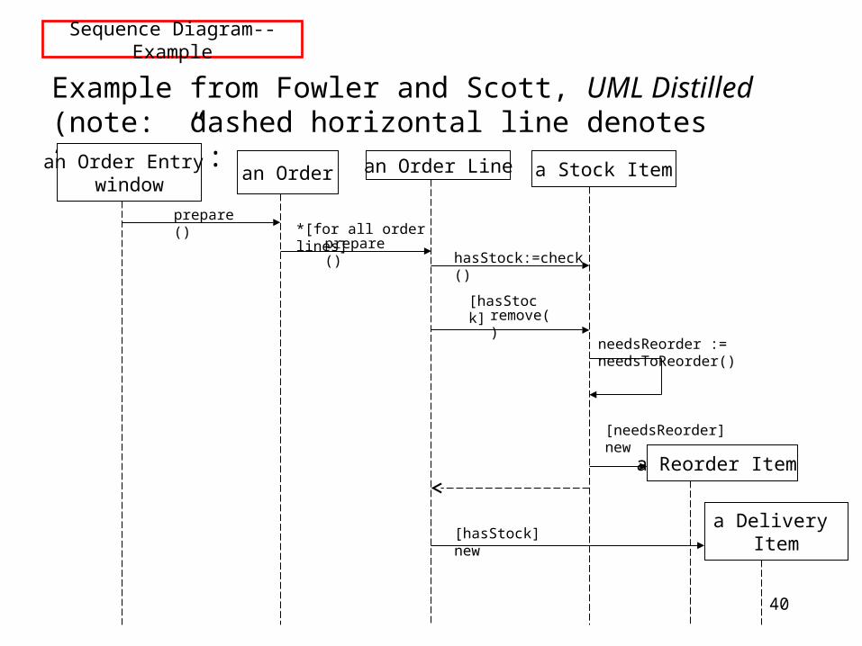
Sequence Diagram--Example
Example from Fowler and Scott, UML Distilled (note: dashed horizontal line denotes “return”):
an Order Entry window
an Order an Order Line a Stock Item
a Reorder Item
a Delivery Item
prepare()*[for all order lines]
prepare()hasStock:=check()
remove()[hasStock]
needsReorder := needsToReorder()
[needsReorder] new
[hasStock] new


![Unified Modeling Language (UML) (Chapter 6). Unified Modeling Language UML October 1994 Three Amigos Grady Booch (Rational Software) [Booch] James.](https://static.fdocuments.us/doc/165x107/56649cba5503460f949822be/unified-modeling-language-uml-chapter-6-unified-modeling-language-.jpg)