1 UDP—User Datagram Protocol An unreliable, connectionless transport layer protocol UDP format....
47
1 UDP—User Datagram Protocol • An unreliable, connectionless transport layer protocol • UDP format. See picture • Two additional functions beyond IP: – Demultiplexing: deliver to different upper layer entities such as DNS, RTP, SNMP based on the destination port # in the header. i.e., UDP can support multiple applications in the same end systems. – (Optionally) check the integrity of entire UDP. (recall IP only checks the integrity of IP header.) • If source does not want to compute checksum, fill checksum with all 0s. • If compute checksum and the checksum happens to be 0s, then fill all 1s. • UDP checksum computation is similar to IP checksum, with two more: – Add extra 0s to entire datagram if not multiple of 16 bits. – Add pseudoheader to the beginning of datagram. UDP pseudoheader
-
Upload
kale-mcmillan -
Category
Documents
-
view
228 -
download
1
Transcript of 1 UDP—User Datagram Protocol An unreliable, connectionless transport layer protocol UDP format....

1
UDP—User Datagram Protocol• An unreliable, connectionless transport layer protocol• UDP format. See picture • Two additional functions beyond IP:
– Demultiplexing: deliver to different upper layer entities such as DNS, RTP, SNMP based on the destination port # in the header. i.e., UDP can support multiple applications in the same end systems.
– (Optionally) check the integrity of entire UDP. (recall IP only checks the integrity of IP header.)
• If source does not want to compute checksum, fill checksum with all 0s.
• If compute checksum and the checksum happens to be 0s, then fill all 1s.
• UDP checksum computation is similar to IP checksum, with two more:– Add extra 0s to entire datagram if not multiple of 16 bits.
– Add pseudoheader to the beginning of datagram. UDP pseudoheader

2
Source Port Destination Port
UDP Length UDP Checksum
Data
0 16 31
Figure 8.16
UDP datagram
Back to UDP—User Datagram Protocol

3
0 0 0 0 0 0 0 0 Protocol = 17 UDP Length
Source IP Address
Destination IP Address
0 8 16 31
Figure 8.17
UDP pseudoheader
1.Pseudoheader is to ensure that the datagram has indeed reached the correct destination host and port.2. The padding of 0s and pseudoheader is only for the computation of checksum and not be transmitted.
Back to UDP—User Datagram Protocol
4
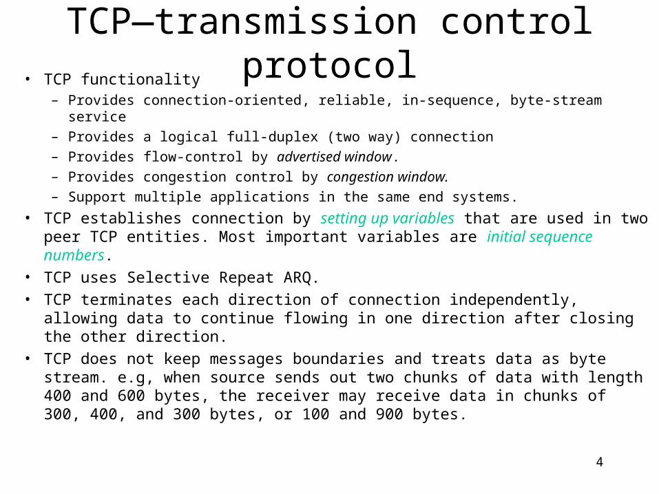
TCP—transmission control protocol• TCP functionality
– Provides connection-oriented, reliable, in-sequence, byte-stream service
– Provides a logical full-duplex (two way) connection
– Provides flow-control by advertised window.
– Provides congestion control by congestion window.
– Support multiple applications in the same end systems.
• TCP establishes connection by setting up variables that are used in two peer TCP entities. Most important variables are initial sequence numbers.
• TCP uses Selective Repeat ARQ.
• TCP terminates each direction of connection independently, allowing data to continue flowing in one direction after closing the other direction.
• TCP does not keep messages boundaries and treats data as byte stream. e.g, when source sends out two chunks of data with length 400 and 600 bytes, the receiver may receive data in chunks of 300, 400, and 300 bytes, or 100 and 900 bytes.
5
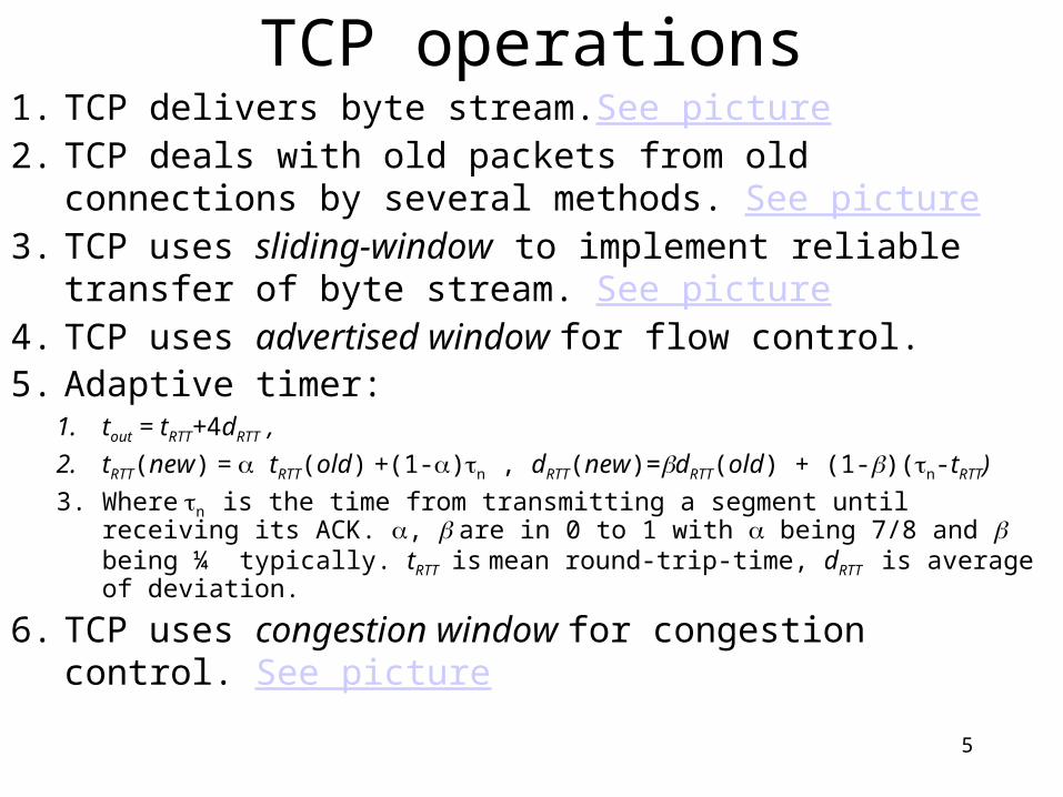
TCP operations1. TCP delivers byte stream.See picture2. TCP deals with old packets from old connections by several
methods. See picture3. TCP uses sliding-window to implement reliable transfer of
byte stream. See picture4. TCP uses advertised window for flow control.5. Adaptive timer:
1. tout = tRTT+4dRTT ,
2. tRTT(new) = tRTT(old) +(1-)n , dRTT(new)=dRTT(old) + (1-)(n-tRTT)
3. Where n is the time from transmitting a segment until receiving its ACK. , are in 0 to 1 with being 7/8 and being ¼ typically. tRTT is mean round-trip-time, dRTT is average of deviation.
6. TCP uses congestion window for congestion control. See picture

6
byte stream
Send buffer
segments
Receive buffer
byte stream
Application Application
ACKs
Transmitter Receiver
Figure 8.18
TCP byte stream
7
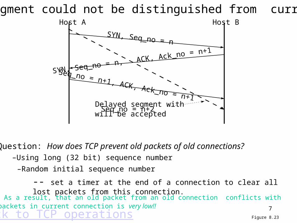
Host A Host B
SYN, Seq_no = n
SYN, Seq_no = n, ACK, Ack_no = n+1
Seq_no = n+1, ACK, Ack_no = n+1Delayed segment withSeq_no = n+2will be accepted
Figure 8.23Back to TCP operations
Question: How does TCP prevent old packets of old connections?
An old segment could not be distinguished from current ones
–Using long (32 bit) sequence number
–Random initial sequence number
-- set a timer at the end of a connection to clear all lost packets from this connection. As a result, that an old packet from an old connection conflicts with packets in current connection is very low!!
8
Octetstransmitted
and ACKed
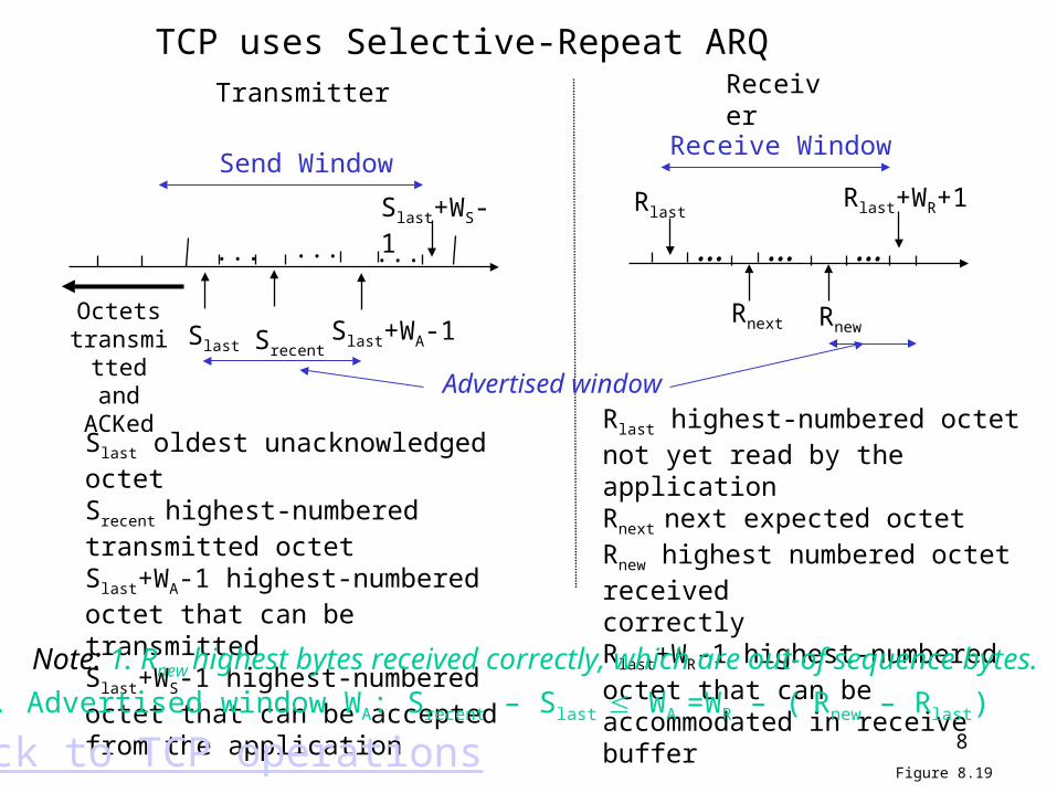
Rlast highest-numbered octet not yet read by the applicationRnext next expected octetRnew highest numbered octet receivedcorrectlyRlast+WR-1 highest-numbered octet that can be accommodated in receive buffer
Transmitter Receiver
Receive Window
Slast
Slast+WS-1
...
Send Window
Srecent
Rnext
... ...
Slast+WA-1
RlastRlast+WR+1
Slast oldest unacknowledged octetSrecent highest-numbered transmitted octetSlast+WA-1 highest-numbered octet that can be transmittedSlast+WS-1 highest-numbered octet that can be accepted from the application
Rnew
Figure 8.19Back to TCP operations
TCP uses Selective-Repeat ARQ
Note: 1. Rnew highest bytes received correctly, which are out-of sequence bytes.
2. Advertised window WA: Srecent – Slast WA =WR – ( Rnew – Rlast)
… … …
Advertised window
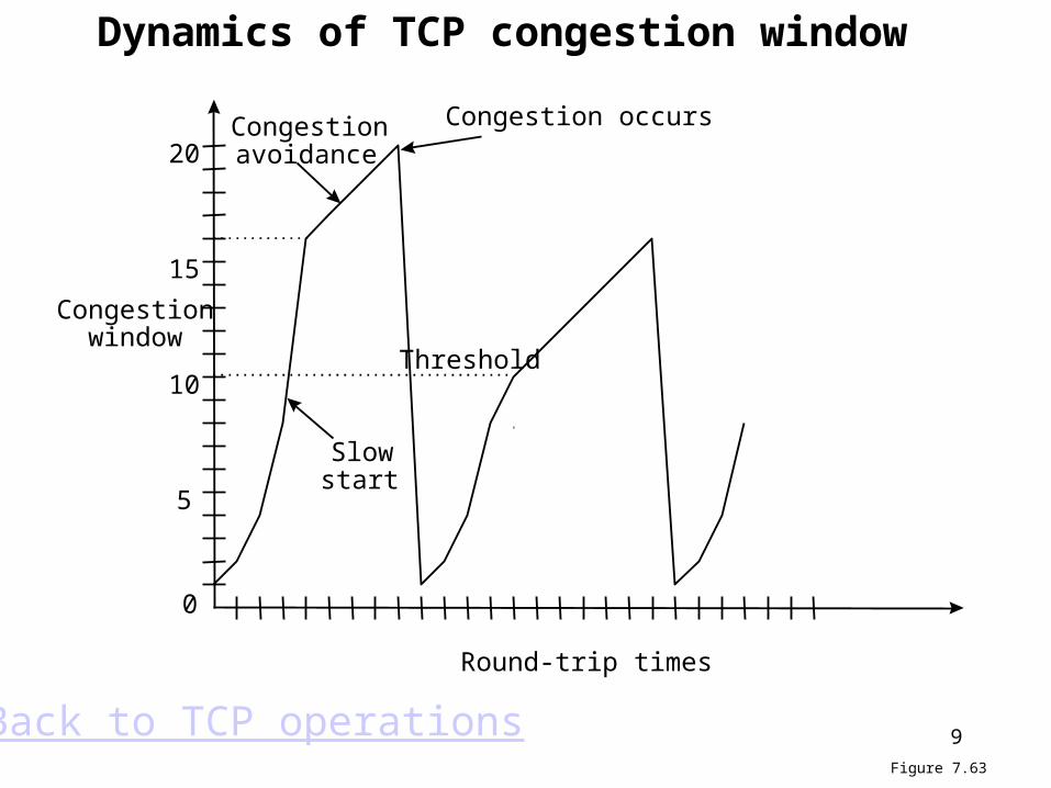
9
Congestionwindow
10
5
15
20
0
Round-trip times
Slowstart
Congestionavoidance
Congestion occurs
Threshold
Figure 7.63
Back to TCP operations
Dynamics of TCP congestion window
10
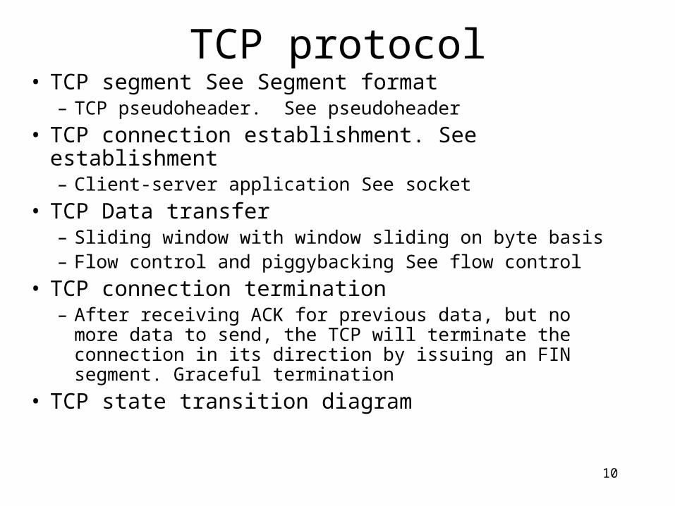
TCP protocol• TCP segment See Segment format
– TCP pseudoheader. See pseudoheader
• TCP connection establishment. See establishment– Client-server application See socket
• TCP Data transfer– Sliding window with window sliding on byte basis– Flow control and piggybacking See flow control
• TCP connection termination– After receiving ACK for previous data, but no more data
to send, the TCP will terminate the connection in its direction by issuing an FIN segment. Graceful termination
• TCP state transition diagram

11
Source Port Destination Port
Sequence Number
Acknowledgement Number
Checksum Urgent Pointer
Options Padding
0 4 10 16 24 31
URG
ACK
PSH
RST
SYN
FIN
HeaderLength Reserved (Advertised) Window Size
Data
Figure 8.20
Back to TCP protocol TCP segment format
1.SYN: request to set a connection. 2. RST: tell the receiver to abort the connection.3. FIN: tell receiver this is the final segment, no more data, i.e, close the connection in this direction.4. ACK: tell the receiver (or sender) that the value is the field of acknowledgment number is valid.5. PSH: tell the receiving TCP entity to pass the data to the application immediately.6. URG: tell the receiver that the Urgent Pointer is valid.
Urgent Pointer: this pointer added to the sequence number points to the last byte of the “Urgent Data”, (the data that needs immediately delivery).

12
0 0 0 0 0 0 0 0 Protocol = 6 TCP Segment Length
Source IP Address
Destination IP Address
0 8 16 31
Figure 8.21
Back to TCP protocol
TCP pseudoheader
The padding of 0s and pseudoheader is only used in computationof checksum but not be transmitted, as in UDP checksum.

13
Host A Host B
SYN, Seq_no = x
SYN, Seq_no = y, ACK, Ack_no = x+1
Seq_no = x+1, ACK, Ack_no = y+1
Figure 8.22
Back to TCP protocol
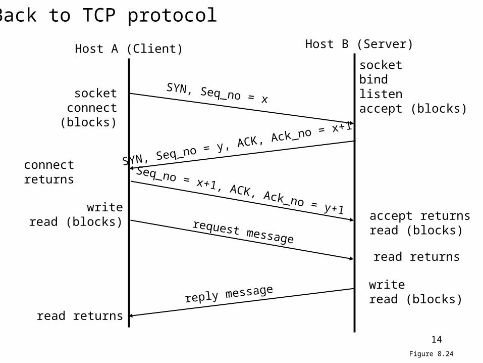
Three-way handshake to set up connection
1. Random initial SN2. Initial SNs in two directions are different3. Initial SNs for two connections are different.4. It should be clear here that
what setting up connection means: both A and B know that they will exchange data, and go into ready state to send and receive data. Most important is that
they agree upon the initial SNs.
14
Host A (Client) Host B (Server)
SYN, Seq_no = x
SYN, Seq_no = y, ACK, Ack_no = x+1
Seq_no = x+1, ACK, Ack_no = y+1
socketbindlistenaccept (blocks)
socketconnect (blocks)
connect returns
accept returnsread (blocks)
writeread (blocks)
read returns
writeread (blocks)
read returns
request message
reply message
Figure 8.24
Back to TCP protocol
15
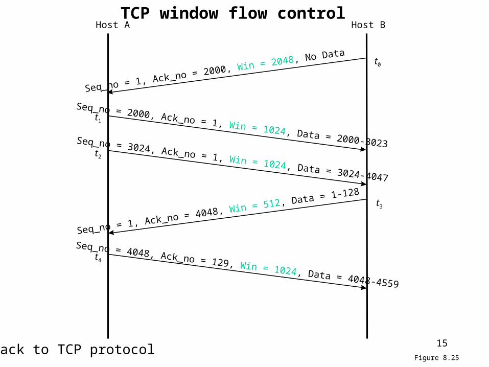
Host A Host B
Seq_no = 2000, Ack_no = 1, Win = 1024, Data = 2000-3023
Seq_no = 1, Ack_no = 4048, Win = 512, Data = 1-128
Seq_no = 3024, Ack_no = 1, Win = 1024, Data = 3024-4047
Seq_no = 4048, Ack_no = 129, Win = 1024, Data = 4048-4559
t1
t2
t3
t4
Seq_no = 1, Ack_no = 2000, Win = 2048, No Data t0
Figure 8.25Back to TCP protocol
TCP window flow control
16
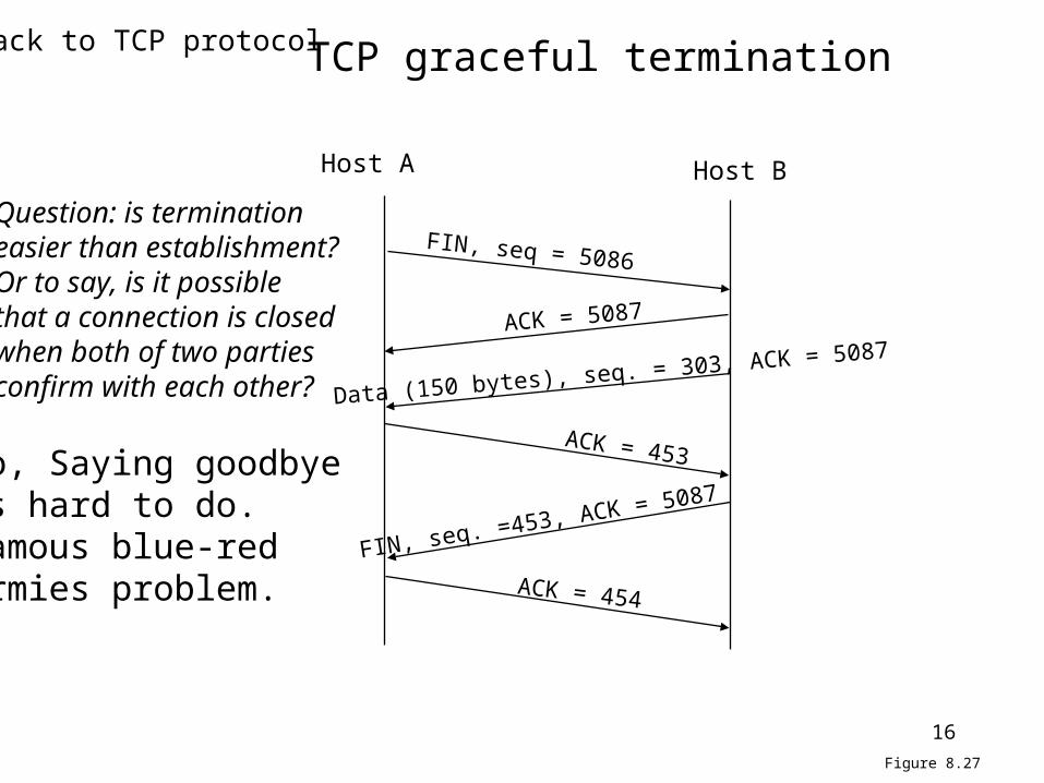
FIN, seq = 5086
ACK = 5087
Data (150 bytes), seq. = 303, ACK = 5087
FIN, seq. =453, ACK = 5087
ACK = 454
Host A Host B
ACK = 453
Figure 8.27
Back to TCP protocol TCP graceful termination
Question: is terminationeasier than establishment?Or to say, is it possiblethat a connection is closed when both of two parties confirm with each other?
No, Saying goodbyeis hard to do.Famous blue-red armies problem.

17
CLOSED
LISTEN
SYN_RCVD
ESTABLISHED
CLOSING
TIME_WAIT
SYN_SENT
FIN_WAIT_1
CLOSE_WAIT
LAST_ACK
FIN_WAIT_2
active open,create TCB
send SYN
passive open,create TCB
send SYN
receive SYN,
send SYN, ACK
receive
RST
receiveACK receive SYN, ACK,send ACKapplic.
close,sendFIN
applic. clo
se,
send FIN
receive FIN,send ACK
receive FINsend ACK
receive FIN, ACK
send ACKreceive
ACK
receive FINsend ACK
receiveACK
applic. closesend FIN
receiveACK
applic. closeor timeout,delete TCB
2MSL timeoutdelete TCB
receive SYN,send ACK
applic.close
Figure 8.28
Thick lines: normal client statesDashed lines: normal server states
Back to TCP protocol
18
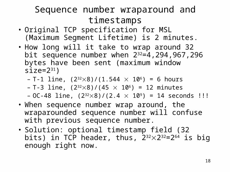
Sequence number wraparound and timestamps
• Original TCP specification for MSL (Maximum Segment Lifetime) is 2 minutes.
• How long will it take to wrap around 32 bit sequence number when 232=4,294,967,296 bytes have been sent (maximum window size=231)– T-1 line, (2328)/(1.544 106) = 6 hours– T-3 line, (2328)/(45 106) = 12 minutes– OC-48 line, (2328)/(2.4 109) = 14 seconds !!!
• When sequence number wrap around, the wraparounded sequence number will confuse with previous sequence number.
• Solution: optional timestamp field (32 bits) in TCP header, thus, 232232=264 is big enough right now.

19
Internet routing protocols• Autonomous system (AS)
– A set of routers or networks technically administrated by a single organization.
– No restriction that an AS must run a single routing protocol– Only requirement is that from outside, an AS presents a consistent picture of
which ASs are reachable through it.
• Three types of ASs:– Stub AS: has only a single connection to outside.– Multihomed AS: has multiple connections to outside, but refuses to carry out
transit traffic– Transit AS: multiple connections to outside and carry transit traffic.
• ASs need to be assigned globally unique AS number (ASN)
20
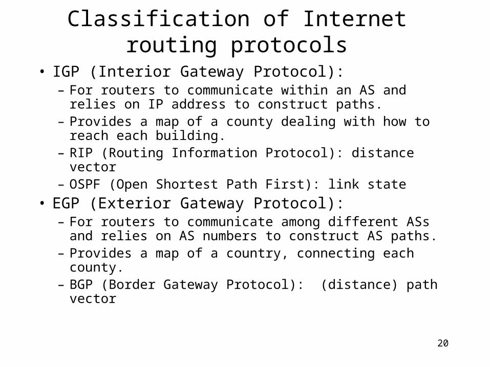
Classification of Internet routing protocols
• IGP (Interior Gateway Protocol):– For routers to communicate within an AS and relies on
IP address to construct paths.– Provides a map of a county dealing with how to reach
each building.– RIP (Routing Information Protocol): distance vector– OSPF (Open Shortest Path First): link state
• EGP (Exterior Gateway Protocol): – For routers to communicate among different ASs and
relies on AS numbers to construct AS paths. – Provides a map of a country, connecting each county.– BGP (Border Gateway Protocol): (distance) path vector
21
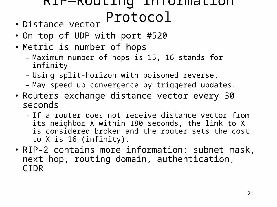
RIP—Routing Information Protocol• Distance vector• On top of UDP with port #520• Metric is number of hops
– Maximum number of hops is 15, 16 stands for infinity– Using split-horizon with poisoned reverse.– May speed up convergence by triggered updates.
• Routers exchange distance vector every 30 seconds– If a router does not receive distance vector from its
neighbor X within 180 seconds, the link to X is considered broken and the router sets the cost to X is 16 (infinity).
• RIP-2 contains more information: subnet mask, next hop, routing domain, authentication, CIDR

22
Command Version Zero
Address Family Identifier Zero
IP Address
Zero
Zero
Metric
0 8 16 31
. . .
Figure 8.32
RIP message format
1. Command: 1: request other routers to send routing information 2: a response containing its routing information
2. Version: 1 or 23. Up to 25 routing information message 3.1 Family identifier: only 2 for IP address 3.2 IP address: can be a host address or a network address 3.3 Metric: 1—15. 16 indicates infinity Problems of RIP: not scalable, slow convergence, counting-to-infinity, therefore replaced By OSPF in 1979.
23
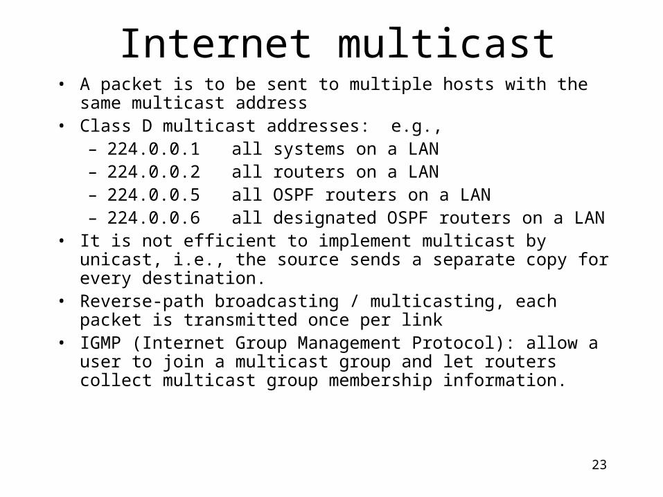
Internet multicast• A packet is to be sent to multiple hosts with the same multicast address• Class D multicast addresses: e.g.,
– 224.0.0.1 all systems on a LAN– 224.0.0.2 all routers on a LAN– 224.0.0.5 all OSPF routers on a LAN– 224.0.0.6 all designated OSPF routers on a LAN
• It is not efficient to implement multicast by unicast, i.e., the source sends a separate copy for every destination.
• Reverse-path broadcasting / multicasting, each packet is transmitted once per link
• IGMP (Internet Group Management Protocol): allow a user to join a multicast group and let routers collect multicast group membership information.

24
Multicasting
S
G1 G1
G1
G1
G3
1
2
3
4
5
6
7
81
2
3
45
1
23
4 1 2
34
5
1 2
3
1
23
1
2
1 2
34
1
2 3
4
G2
G3
3
4
• Source S sends packets to multicast group G1

25
Multicast Routing• Multicast routing useful when a source wants to
transmit its packets to several destinations simultaneously
• Relying on unicast routing by transmitting each copy of packet separately works, but can be very inefficient if number of destinations is large
• Typical applications is multi-party conferencing over the Internet
• Example: Multicast Backbone (MBONE) uses reverse path multicasting

26
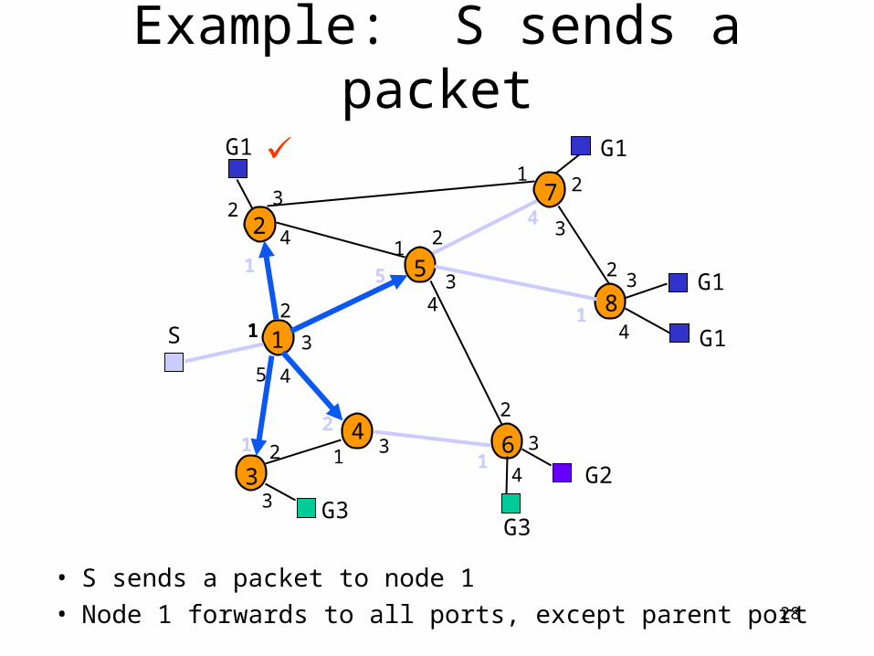
Reverse-Path Broadcasting (RPB)
• Fact: Set of shortest paths to the source node S forms a tree that spans the network– Approach: Follow paths in reverse direction
• Assume each router knows current shortest path to S– Upon receipt of a multicast packet, router records the packet’s source
address and the port it arrives on– If shortest path to source is through same port (“parent port”), router
forwards the packet to all other ports– Else, drops the packet
• Loops are suppressed; each packet forwarded by a router exactly once• Implicitly assume shortest path to source S is same as shortest path from
source– If paths asymmetric, need to use link state info to compute shortest paths
from S
27
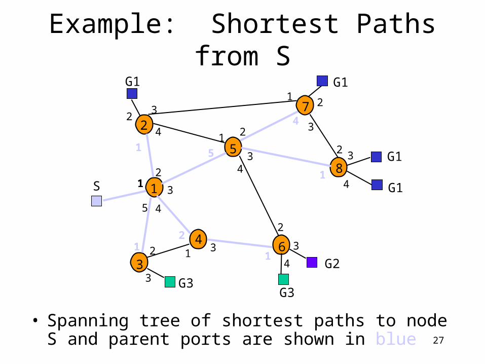
Example: Shortest Paths from S
• Spanning tree of shortest paths to node S and parent ports are shown in blue
S
G1 G1
G1
G1
G3
1
2
3
4
5
6
7
81
2
3
45
1
23
4 1 2
34
5
1 2
3
1
23
1
2
1 2
34
1
2 3
4
G2
G3
3
4
28
Example: S sends a packet
• S sends a packet to node 1• Node 1 forwards to all ports, except parent port
S
G1 G1
G1
G1
G3
1
2
3
4
5
6
7
81
2
3
45
1
23
4 1 2
34
5
1 2
3
1
23
1
2
1 2
34
1
2 3
4
G2
G3
3
4

29
Example: Hop 1 nodes broadcast
• Nodes 2, 3, 4, and 5 broadcast, except on parent ports• All nodes, not only G1, receive packets
S
G1 G1
G1
G1
G3
1
2
3
4
5
6
7
81
2
3
45
1
23
4 1 2
34
5
1 2
3
1
23
1
2
1 2
34
1
2 3
4
G2
G3
3
4

30
Example: Broadcast continues
• Truncated RPB (TRPB): Leaf routers do not broadcast if none of its attached hosts belong to packet’s multicast group
S
G1 G1
G1
G1
G3
1
2
3
4
5
6
7
81
2
3
45
1
23
4 1 2
34
5
1 2
3
1
23
1
2
1 2
34
1
2 3
4
G2
G3
3
4

31
Internet Group Management Protocol (IGMP)
• Internet Group Management Protocol: – Host can join a multicast group by sending an IGMP message to
its router• Each multicast router periodically sends an IGMP query
message to check whether there are hosts belonging to multicast groups– Hosts respond with list of multicast groups they belong to– Hosts randomize response time; cancel response if other hosts
reply with same membership• Routers determine which multicast groups are associated
with a certain port • Routers only forward packets on ports that have hosts
belonging to the multicast group

32
Multicast programming• 2.1 Multicast addresses.
– 224.0.0.0---247.255.255.255 • 2.2 Levels of conformance.
– 0: no, 1: sending, 2: receiving• 2.3 Sending Multicast Datagrams.
– Open UDP socket, and send to multicast address – TTL
• 0 Restricted to the same host. • 1 Restricted to the same subnet. • <32 Restricted to the same site, organization or department. • <64 Restricted to the same region. • <128 Restricted to the same continent. • <255 Unrestricted in scope. Global.
• 2.4 Receiving Multicast Datagrams. – Joining multicast group– Drop multicast group
• Mapping of IP Multicast Addresses to Ethernet/FDDI addresses.

33
Multicast functions
• int getsockopt(int s, int level, int optname, void* optval, int* optlen);
• int setsockopt(int s, int level, int optname, const void* optval, int optlen);
• setsockopt() getsockopt() • IP_MULTICAST_LOOP yes yes • IP_MULTICAST_TTL yes yes • IP_MULTICAST_IF yes yes • IP_ADD_MEMBERSHIP yes no • IP_DROP_MEMBERSHIP yes no
• http://www.ibiblio.org/pub/Linux/docs/HOWTO/other-formats/html_single/Multicast-HOWTO.html#ss2.1

34
IPv6 (IPng): IPv4 is very successful but the victim of its own success.
• Longer address field:– 128 bits can support up to 3.4 x 1038 hosts
• Simplified header format: – Simpler format to speed up processing of each header– All fields are of fixed size– IPv4 vs IPv6 fields:
• Same: Version• Dropped: Header length, ID/flags/frag offset, header checksum• Replaced:
– Datagram length by Payload length– Protocol type by Next header– TTL by Hop limit– TOS by traffic class
• New: Flow label

35
Other IPv6 Features• Flexible support for options: more efficient and
flexible options encoded in optional extension headers• Flow label capability: “flow label” to identify a
packet flow that requires a certain QoS• Security: built-in authentication and confidentiality• Large packets: supports payloads that are longer than
64 K bytes, called jumbo payloads.• Fragmentation at source only: source should check
the minimum MTU along the path• No checksum field: removed to reduce packet
processing time in a router
36
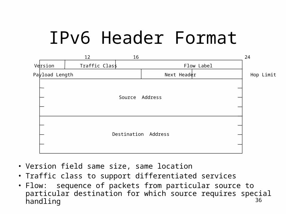
IPv6 Header Format
• Version field same size, same location• Traffic class to support differentiated services• Flow: sequence of packets from particular source to particular
destination for which source requires special handling
Version Traffic Class Flow Label
Payload Length Next Header Hop Limit
Source Address
Destination Address
0 4 12 16 24 31

37
IPv6 Header Format
• Payload length: length of data excluding header, up to 65535 B• Next header: type of extension header that follows basic header• Hop limit: # hops packet can travel before being dropped by a router
Version Traffic Class Flow Label
Payload Length Next Header Hop Limit
Source Address
Destination Address
0 4 12 16 24 31

38
IPv6 Addressing• Address Categories
– Unicast: single network interface– Multicast: group of network interfaces, typically at different
locations. Packet sent to all.– Anycast: group of network interfaces. Packet sent to only one
interface in group, e.g. nearest.• Hexadecimal notation
– Groups of 16 bits represented by 4 hex digits– Separated by colons
• 4BF5:AA12:0216:FEBC:BA5F:039A:BE9A:2176
– Shortened forms:• 4BF5:0000:0000:0000:BA5F:039A:000A:2176 • To 4BF5:0:0:0:BA5F:39A:A:2176• To 4BF5::BA5F:39A:A:2176
– Mixed notation:• ::FFFF:128.155.12.198

39
Example

40
Address Types based on PrefixesBinary prefix Types Percentage of address space
0000 0000 Reserved 0.39
0000 0001 Unassigned 0.39
0000 001 ISO network addresses 0.78
0000 010 IPX network addresses 0.78
0000 011 Unassigned 0.78
0000 1 Unassigned 3.12
0001 Unassigned 6.25
001 Unassigned 12.5
010 Provider-based unicast addresses 12.5
011 Unassigned 12.5
100 Geographic-based unicast addresses 12.5
101 Unassigned 12.5
110 Unassigned 12.5
1110 Unassigned 6.25
1111 0 Unassigned 3.12
1111 10 Unassigned 1.56
1111 110 Unassigned 0.78
1111 1110 0 Unassigned 0.2
1111 1110 10 Link local use addresses 0.098
1111 1110 11 Site local use addresses 0.098
1111 1111 Multicast addresses 0.39

41
Special Purpose Addresses
• Provider-based Addresses: 010 prefix
– Assigned by providers to their customers
– Hierarchical structure promotes aggregation
• Registry ID: ARIN, RIPE, APNIC
• ISP
• Subscriber ID: subnet ID & interface ID
• Local Addresses: do not connect to global Internet
– Link-local: for single link
– Site-local: for single site
– Designed to facilitate transition to connection to Internet
010 Registry ID Provider ID Subscriber ID Subnet ID Interface ID
n bits m bits o bits p bits (125-m-n-o-p) bits

42
Special Purpose Addresses• Unspecified Address: 0::0
– Used by source station to learn own address
• Loopback Address: ::1• IPv4-compatible addresses: 96 0’s + IPv4
– For tunneling by IPv6 routers connected to IPv4 networks
– ::135.150.10.247
• IP-mapped addresses: 80 0’s + 16 1’s + IPv4– Denote IPv4 hosts & routers that do not support IPv6

43
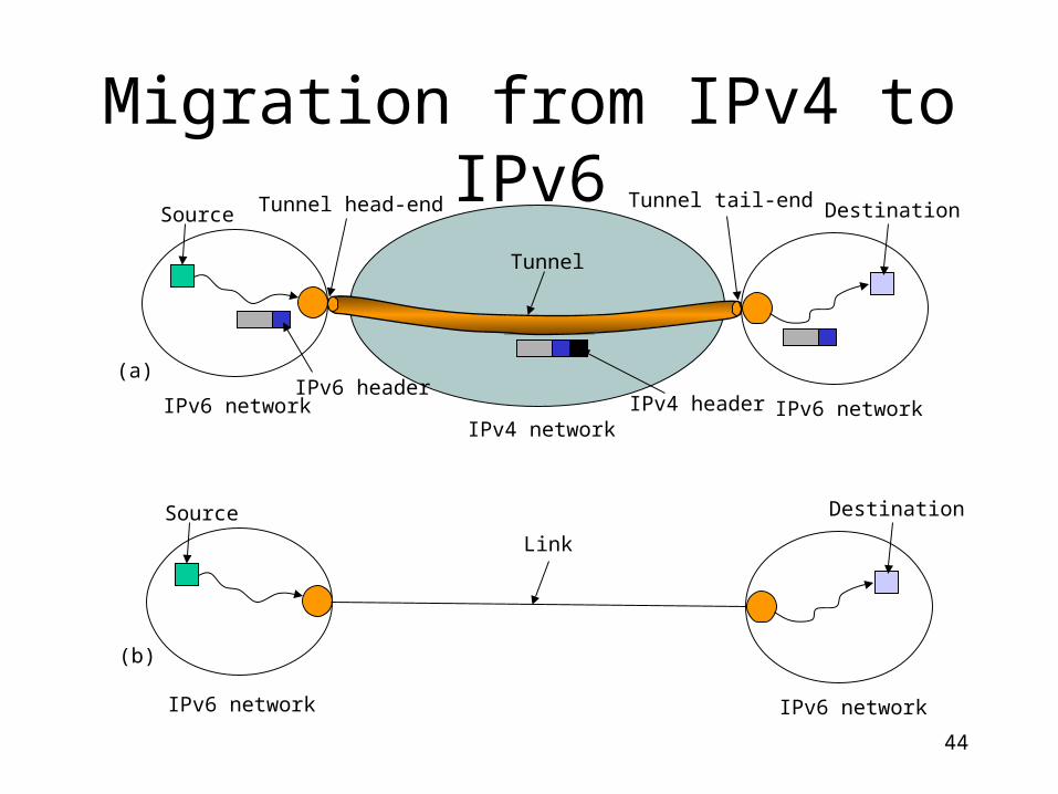
Migration from IPv4 to IPv6
• Gradual transition from IPv4 to IPv6• Dual IP stacks: routers run IPv4 & IPv6
– Type field used to direct packet to IP version
• IPv6 islands can tunnel across IPv4 networks– Encapsulate user packet insider IPv4 packet– Tunnel endpoint at source host, intermediate
router, or destination host– Tunneling can be recursive
44
Migration from IPv4 to IPv6
Source Destination
IPv6 network IPv6 network
Link
(b)
Source Destination
IPv6 networkIPv4 network
IPv6 network
Tunnel
Tunnel head-end Tunnel tail-end
IPv6 headerIPv4 header
(a)

45
DHCP (Dynamic Host Configuration Protocol)
• A host broadcasts a DHCP discovery message in its physical network for an IP address.
• Server(s) reply with DHCP offer message• The host selects one IP address and broadcasts a
DHCP request message including the IP address• The selected server allocates the IP address and
sends back a DHCP ACK message with a lease time T, two thresholds T1 (=0.5T), T2(=0.875T)– when T1 expires, the host asks the server for extension.– If T2 expire, the host broadcasts DHCP request to any
server on the network– If T expires, the host relinquishes the IP address and
reapply from scratch.

46
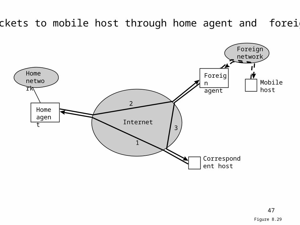
Mobile IP
• Mobile host, home agent, foreign agent• If mobile host is currently at the same network
with HA (home agent), the packet to the mobile host will be broadcast to it.
• If mobile host moves to another network, the mobile host will register itself with FA (foreign
agent) and gets a new care-of IP address. Then packet is sent to HA, which will forward to the FA and FA continues to forward to destination.
47
Home agent
Foreign agent
Home network
Foreign network
Internet
Correspondent host
Mobile host
1
2
3
Figure 8.29
Deliver packets to mobile host through home agent and foreign agent


![User Datagram Protocol (UDP) UDP [RFC 768] UDP Socket](https://static.fdocuments.us/doc/165x107/586e022b1a28ab3c168b57c2/user-datagram-protocol-udp-udp-rfc-768-udp-socket.jpg)