1 Test Methods for Fiber Reinforced Polymer (FRP) Composites John J. “Jack” Lesko Department of...
52
1 Test Methods for Fiber Reinforced Polymer (FRP) Composites John J. “Jack” Lesko Department of Engineering Science & Mechanics [email protected] (540) 231-5259 Introduction to Polymeric Adhesives and Composites Short Course Copyright, 2004, J J Lesko, ESM, Virginia Tech, Blacksburg, Virginia. All rights reserved.
-
Upload
christina-tetley -
Category
Documents
-
view
224 -
download
0
Transcript of 1 Test Methods for Fiber Reinforced Polymer (FRP) Composites John J. “Jack” Lesko Department of...

1
Test Methods for Fiber Reinforced Polymer (FRP) Composites
John J. “Jack” LeskoDepartment of Engineering Science & Mechanics
[email protected] (540) 231-5259
Introduction to Polymeric Adhesives and Composites Short Course
Copyright, 2004, J J Lesko, ESM, Virginia Tech, Blacksburg, Virginia. All rights reserved.

2
Partial List of Standardization Groups
_ USA– American Society for Testing and Materials (ASTM)– MIL-HDBK-17 Committee (http://www.mil17.org/)– Suppliers of Advanced Composite Materials Association (SACMA)
_ Europe– Deutsches Institut Fur Normung (DIN)– Association Francaise de Normalization (AFNOR)– British Standards Institute (BSI)
_ East– Japanese Industrial Standards
_ International– International Organization for Standardization (ISO)

3
ASTM Standard Test Methods*
DefinitionsD3878--Definitions of Terms Relating to High-Modulus Reinforcing Fibers and Their
Composites
Fiber/Matrix PrepregC613--Test Method for Resin Content of Carbon and Graphite Prepregs by Solvent Extraction
D3379--Test Method for Tensile Strength and Young’s Modulus for High Modulus Single-Filament Materials
D3529--Test Method for Resin Solids Content of Carbon Fiber-Epoxy Prepreg
D3530--Test Method for Volatiles Content of Carbon Fiber-Epoxy Prepreg
D3531--Test Method for Resin Flow of Carbon Fiber-Epoxy Prepreg
D3532--Test Method for Gel Time of Carbon Fiber-Epoxy Prepreg
D3544--Guide for Reporting Test Methods and Results on High Modulus Fibers
D3800--Test Method for Density of High-Modulus Fibers
D4102--Test Method for Thermal Oxidative Resistance of Carbon Fibers
* Found in Vol. 15.03 of ASTM Annual Book of Standards

4
Key to Successful FRP Testing

5
Damage & Strength of Composites

6
Composite Damage Modes
A
B
C
Tensile Failure Compression FailureMatrix Cracking & Delamination

7
Tensile Strength

8
The tensile strength of a composite is controlled by the interface/phase, influencing the local stress concentrations and the size of the “ineffective length - ”....
f
f
0f
1 2 3 4 5 6 7 8

9
Tensile Stress Concentration at a Fiber Break

10
Tensile Strength Models
fm
tff
tt V1XVXX
A very crude approximation of tensile strength from the Rule of Mixtures
More sophisticated models includeBatdorf, S. B. “Tensile strength of unidirectional reinforced composites--I,” Journal of Reinforced Plastics and Composites, Volume 1 (1982), pp.153-176.
Gao, Z. and Reifsnider, K. L. “Micromechanics of tensile strength in composite systems,” Composite Materials: Fatigue and Fracture, Fourth Volume, ASTM STP 1156, W. W. Stinchcomb and N. E. Ashbaugh, Eds., ASTM, Philadelphia, (1993), pp. 453-470.
Reifsnider, K., Iyengar, N., Case, S. and Xu, Y. “Kinetic Methods for Durability and Damage Tolerance Design of Composite Components,” Keynote Address, Conference on Composite Materials, Japan Society for Mechanical Engineers, June 26, 1995, Tokyo.

11
Stresses Around Filler Particles
Monette, et al, J. Appl. Physics, 75 (3), 1994, 1442-1455.

12
Pultrusion Fabrication Flaw
90º Tow
0º Tow
“As received” pultruded cross ply laminate (E-glass/Derakane 441-400)
Microcrack -1.2mm long by .25mm wide

13
Transverse Strength Models
f2
m2
ffm
ttE
E1VV1YY
11
E
Er
E
YEY
f2
m2
hm2
mt
2t rV
hf 2
3
11
E
Er
E
YEY
f2
m2
sm2
mt
2t rV
sf 4
Gibson, R. F. Principles of Composite Material Mechanics, McGraw Hill, New York (1994)

14
0° and Laminate Tension Testing of Composites
Concerns in the Assessment of Modulus and StrengthUniformity of stress state• Failure in the gage section (common problem between test specimens)
• Failure modes• Material misalignment (1° misalignment can yield a 30% strength reduction)
• Specimens with cross reinforcement
Gripping• Transition region concentration (common problem in all specimens)• Tab geometry• Grip region geometry• Grip pressure

15
0° and Laminate Tension Testing of Composites
Specimen Types Used in Tensile Testing Straight-Sided Coupon--MRG Preferred
With and without tabs ASTM D638 Type I “Dogbone” Specimen Linear Tapered “Bowtie” Specimen
30% lower 0° strength compared to straight-sided specimen 10% lower 0° strength compared to dogbone specimen Woven cross-ply strengths dogbone or tabbed specimen
Streamline Specimen Comparable to straight-sided for 0°
16
Straight-Sided Specimen
Advantages: No specimen tapering required; better results with cross-reinforced materialsDisadvantages: Tabbing required; tab s-concentration; tight tolerances in thickness
17
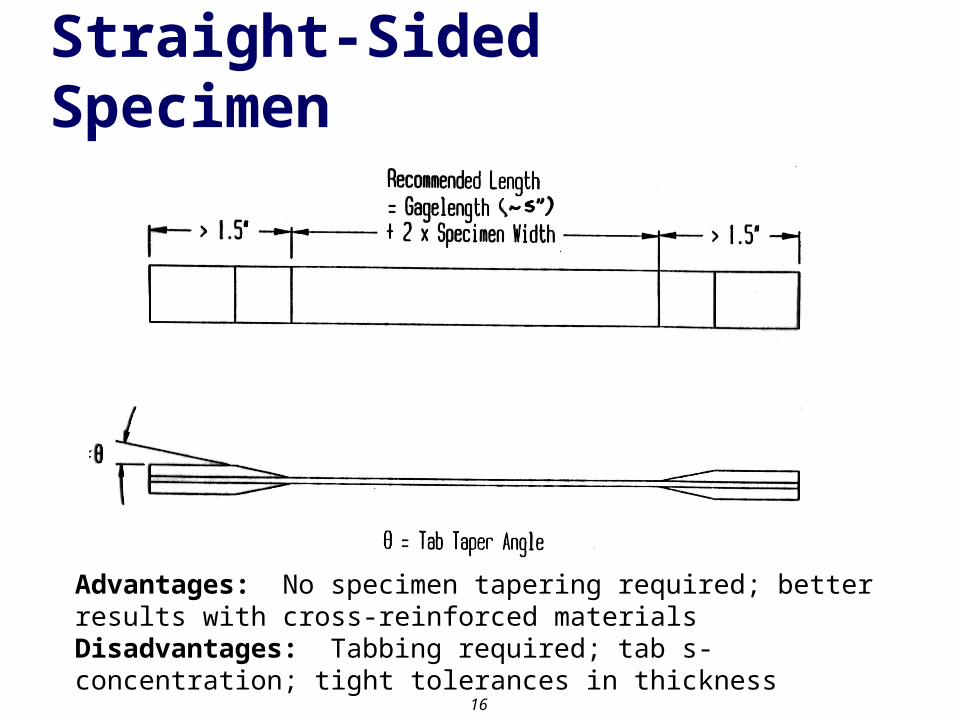
Typical Failure Modes in Straight-Sided Coupons
(Acceptable & common in unidirectional specimens)
(Acceptable & common
in 90° or 90° dominated layups)
(May be found in crossply layups; unacceptable)
(Unacceptable)

18
Typical Tab Failures in Straight-Sided Coupons

19
ASTM D 638 Type I “Dogbone” Specimen
Advantages: No tabbing required; load introduction less of an issueDisadvantages: Careful specimen machining required; not suitable for unidirectional material
20
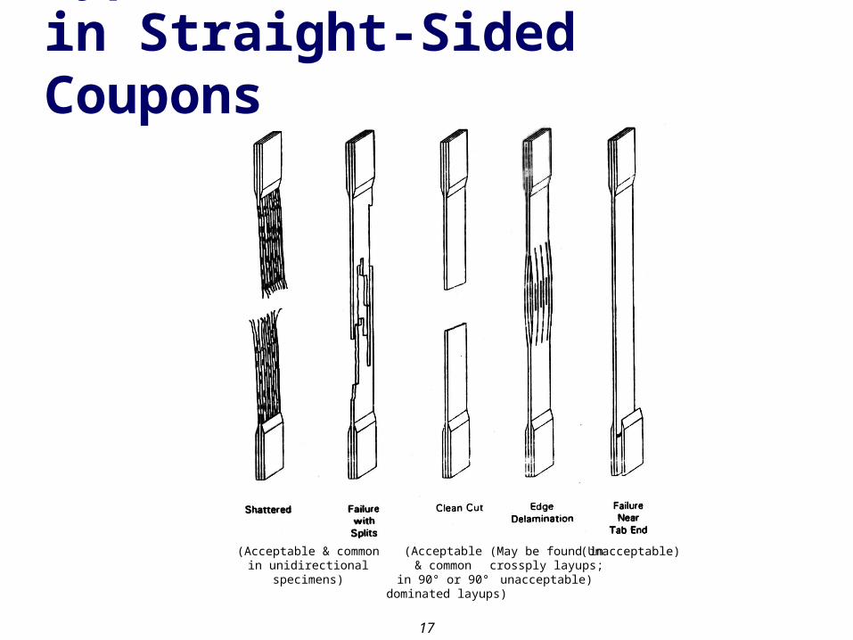
Streamline Specimen
Advantages: No tabbing required; load introduction less of an issue; comparable to straight-sidedDisadvantages: Careful specimen machining required; not suitable for unidirectional material; large specimen (12” [0°/90°]s; 24” [0°]) in order to keep the shear stresses low at the transition region

21
Linear-Taped “Bowtie” Specimen
Advantages: No tabbing required; load introduction less of an issueDisadvantages: Careful specimen machining required; not suitable for unidirectional material; large specimen

22
Effect of Misalignment in Unidirectional Specimens

23
Compression Strength
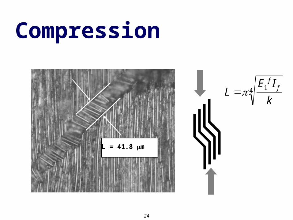
24
Compression
L = 41.8 m
LE I
k
ff 14

25
Compression Strength
fm
cff
cc V1XVXX
An approximation of crushing strength from the Rule of Mixtures
Co
mp
ress
ion
Str
eng
th
Crushing
Buckling
Slenderness ratio (r/L)

26
Compression Strength
L
S S
Matrix
Fiber
Origin of Buckling Fiber's Sine Wave
c
c
2sin
2
GG2
r
kLG
L12
rE
E
V1EVEX
m12m
1232f
2m
122
32ff
1f1
fm
1ff
1c
L
s
4 ff
1
k
IEL 0L1
Ebk
fm
2ff
2
f2
m2
V1EVE
EEE
fm
12ff
12 V1V
Xu, Y. and Reifsnider, K. L. “Micromechanical modeling of composite compressive strength,” Journal of Composite Materials, Vol. 27 (6), (1993), pp. 572-588.

27
Compression Strength
Fleck, N. A. and Budiansky, B. “Compressive failure of fibre composites due to microbuckling,” IUTAM Symposium, Troy, New York, May 29-June 1, (1990), pp. 235-273.
fiber
kink band T
T
L
L
1n
y7
31
G
n
1n
yn
1c
1n7
3n1
GX
Ramberg-Osgood shear response

28
Compression Testing of Composites
Concerns in the Assessment of Modulus and StrengthUniformity of stress stateEnd loadedShear loadedGage section dimensionsSandwich beamGrippingStressconcentrationTab geometryTabbing materialAlignmentBucklingFailure modesSpecimen machining toleranceFixture characteristics

29
Compression Testing of Composites
Classes of Test MethodsShear Loaded - PreferredCelanese & Wyoming modified Celanese IITRI (Illinois Institute of Technology Research Institute) & Wyoming modified IITRI
End LoadedBoeing Compression ASTM D695 & Wyoming modified D695Wyoming End Loaded Side Supported (ELSS)RAE (Royal Aircraft Establishment)Short Block Compression
Sandwich BeamASTM D3410, Method C--FlexureAxially Loaded Sandwich Column

30
IITRI - ASTM D3410
Advantages: Alignment; high data averages and low scatter; large specimens possibleDisadvantages: Expense; specimen tabbing & machining critical; tab s-concentration

31
Celanese: ASTM D3410
Advantages: Alignment; high data averages and low scatter; long-standing test fixtureDisadvantages: Specimen tabbing & machining critical; tab s-concentration; sensitive to fixture accuracy; expense (latter two concerns addressed in Wyoming-modified)
32
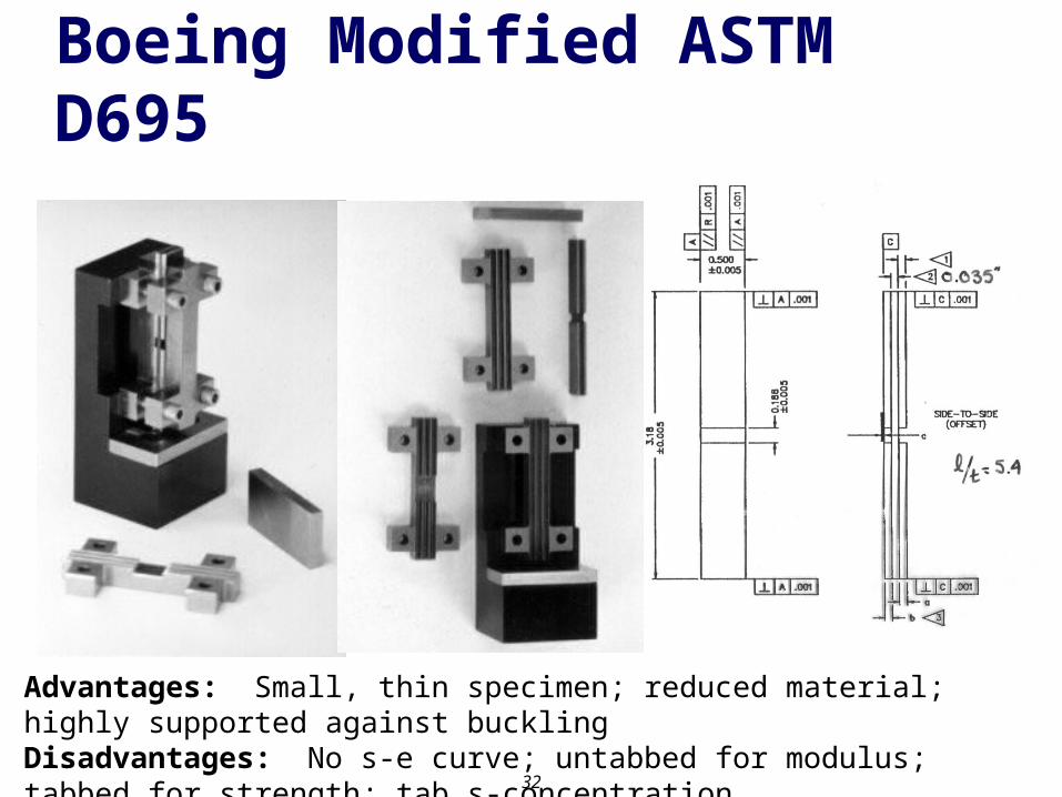
Boeing Modified ASTM D695
Advantages: Small, thin specimen; reduced material; highly supported against bucklingDisadvantages: No s-e curve; untabbed for modulus; tabbed for strength; tab s-concentration

33
Wyoming End Loaded Side Supported (ELSS)
Advantages: No tabbing required; simple fixture; inexpensive; simple alignment; some shear loadingDisadvantages: End crushing for highly orthotropic specimens; support s-concentration; specimen tolerances critical

34
Sandwich Beam Flexure - ASTM D3410 (ASTM C 393)
Advantages: Simple fixture; reliable results with proper specimen (core) designDisadvantages: Large specimens (materials expense); failure must occur in compressive face sheet

35
Axially Loaded Sandwich Column
Advantages: Simple fixture; simple data analysis; standard compression fixtureDisadvantages: Expense in fabricating sandwich panel; end crushing; end s-concentration

36
Other Compression Tests Block Compression Test
Advantages: Simple untabbed specimen; simple fixture; inexpensive
Disadvantages: Thick specimen required; end crushing; end -concentration; misalignment sensitive
RAE Compression Test Advantages: No tabbing required; simple fixture;
inexpensive; shear and end loading Disadvantages: Not widely used; tolerance sensitive
for thickness taper; misalignment upon debonding; specimen buckling

37
Shear Strength

38
Shear Strength Models
rV
hf 2
3
rV
sf 4
Gibson, R. F. Principles of Composite Material Mechanics, McGraw Hill, New York (1994)
f12
m12
ffm
G
G1VV1SSSS
11
G
Gr
G
SSGSS
f12
m12
hm12
m
12
11
G
Gr
G
SSGSS
f12
m12
sm12
m
12
39
Shear Testing of Composites
Concerns in the Assessment of Modulus and Strength
In-plane: 12
Interlaminar: 13
Uniformity of Stress State Failure in the gage section (common problem between test specimens) Failure modes: buckling out of plane; scissoring Material alignment Uniform shear
Load Introduction Transition region concentration (common problem in all specimens) Loading arrangement and assessment of results Grip region geometry

40
Shear Testing of CompositesIn-plane: 12 Iosipescu ASTM D5379 (Preferred for shear strength) (45)ns Tension ASTM D3518 (Preferred for modulus) Off-axis Tension Rail Shear ASTM D4255 Torsion of bar (circular/rectangular) Torsion of a tube ASTM D5448
Interlaminar: 13 Short Beam Shear ASTM D2344 Iosipescu ASTM D5379 (experimental)
bonded laminates

41
Shear Directions3
2
1Material Coordinate
System1, 2, 3
S23
S23
S12
S12
S13
S13

42
Iosipescu Shear Test ASTM D5379
Advantages: Excellent shear strength measurement; small specimen; 0°, 90°, [0°/90°]ns layupsDisadvantages: Tight tolerances on specimen; alignment; twist failure; quality fixture required; expense
43
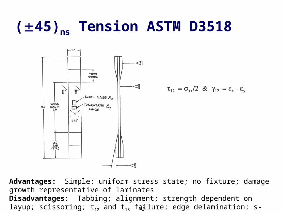
(45)ns Tension ASTM D3518
Advantages: Simple; uniform stress state; no fixture; damage growth representative of laminatesDisadvantages: Tabbing; alignment; strength dependent on layup; scissoring; t12 and t13 failure; edge delamination; s-concentration due to tabs

44
Short Beam Shear ASTM D2344
Advantages: Simple test and fixture; small specimenDisadvantages: Load introduction; no strain measurement; no modulus measurement; improper assumption of parabolic stress distribution; mixed mode failure

45
Stress Distribution in a Short Beam Shear Specimen
Elasticity SolutionBeam Theory

46
Interlaminar Fracture

47
0
100
200
300
400
500
600
700
0 0.01 0.02 0.03 0.04
Displacement, m
Load
, P(N
)Double Cantilever Beam (DCB) Test Data – ASTM D5528
a
P
a1a2
a3
an

48
DCB Data Reduction: Modified Beam Theory
y = 0.429941x + 0.001997R2 = 0.9997
0
0.01
0.02
0.03
0.04
0.05
0.06
0.07
-0.05 0 0.05 0.1 0.15 0.2
Crack Length, a [m]
Cub
e R
oot o
f Com
plia
nce
C 1/
3 (J
/m2 )
1/3
x
1m
•Find C:
•Plot C1/3 vs a
•Find fit:
a
P
PC
)xa(mC / 31
23 23( )
2I
Pm a x
b G b=width

49
DCB Data Reduction: Compliance Calibration Method
2
2I
m P
ba
G
m2
1
•Find C:
•Plot log(C) vs log(a)
•Find the slope m2
PC
a
P
log(C
)
log(a)
b=width

50
DCB Data Reduction: Compliance Calibration Method
3
2/33
2I
PC
m bhG
m3
1
•Find C:
•Plot a/h vs C1/3
•Find the slope m3
PC
a
P
a/h
C1/3
b=width

51
Edge Notch Flexure (ENF)P
a
L L
b=widthLo
ad,
P
Mid-span Displacement,
95% of 1/C
1/CPMax
P95%Pnl
3
3
4bCh
LEflex
313
3
8/
flexcorr
CbhEa
2
3 3
9
2 (2 3 )corr i
IIcorr
Ca P
b L a
G
Of the uncracked region

52
QUESTIONS
A
B
C