1 Taco Variable Speed Drives Design/Commissioning Tips ... · PDF file2 Taco Variable Speed...
16
Taco Variable Speed Drives Design/Commissioning Tips Design/Commissioning Tips for Variable Speed Pumping Systems
Transcript of 1 Taco Variable Speed Drives Design/Commissioning Tips ... · PDF file2 Taco Variable Speed...

1
Taco Variable Speed Drives Design/Commissioning Tips
Design/CommissioningTips for Variable Speed Pumping Systems

2
Taco Variable Speed Drives Design/Commissioning Tips
Differential Pressure TransmittersThe main goal of the secondary chilled water system is to distribute the correct amount of water to satisfy the load. It must first accurately monitor the system for changes in load dynamics.
Secondly, it must respond to these load changeswith the “correct” amount of flow.
Typically a differential pressure sensor is the devicechosen for feedback in a building management system.
Photo Mfg. Name Model No. Accuracy Differential
PressurePressure
RangeBurst
Pressure Output
Taco DPS629 +/- 0.5% FS 0-25psid 50 psid 250 psi 4-20 mA | 0-10 VDC
Taco DPS3100 +/- 0.075% FS 1-100psi -14.5 to 2000 psi 10000 psi 4-20 mA | 0-10 VDC
Differential Pressure Transmitter Types

3
Taco Variable Speed Drives Design/Commissioning Tips
Differential PressureTransmitter Installation
Tag: AHU-________ HWTag: AHU-________ HWTag: AHU-________ HWTag: AHU-________ CWTag: AHU-________ CWTag: AHU-________ CW
Supply Upstream(High Side)ManifoldBlock Valve
Downstream(Low Side)ManifoldBlock Valve
DP XMTR Isolation Valve
High Gauge
DP XMTR
Low Gauge
DP XMTR Isolation Valve
Return
NOTES:• Material of construction as required by application.• DP Transmitter may be wall mounted or pipe stand mounted.• Orientation of DP XMTR and pipes has no effect on performance.• Gauges can be rotated for best viewing.
It is critical that the design engineer tell the installing contractor WHERE in the system they would like the sensors installed. This is most easily done with a small schedule indicating which terminal unit the engineer wants.

4
Taco Variable Speed Drives Design/Commissioning Tips
Differential Pressure Transmitter QuantityQuantity:
Three sensors can provide a veryaccurate picture of system demand.
• One for the longest run (Student dorm or remote part of East Campus) • One for the dominant load (New basketball arena in Central Campus) • One for another zone (Administrative office located in remote part of West Campus)
For buildings with a very asymmetric layout,other sensors may be added to monitor each zone.
TIP: Provide three way valves or bypass at remote points of the system.

5
Taco Variable Speed Drives Design/Commissioning Tips
Determining Differential Pressure SetpointThe sensor must keep enough pressure differential across the supply and return to “push” the design capacity flow through the coil and control valve.
Setpoint = Sum of coil pressure drop + control valve pressure drop at design conditions (17’)
DP
3 psi (7’) PD
10’ PD

6
Taco Variable Speed Drives Design/Commissioning Tips
Sensor PlacementWhether the Dp sensor is located at the pump discharge or the end of the pipe loop with the highest head does not affect the ability of the pumps to move the design flow. However, it dramatically affects the amount of energy consumed by the pumps.
A ∆P sensor located near the pump discharge will save very little energy. The setpoint must be equal to the pressure drop through all the coils, control valves and connecting piping downstream of the sensor at design flow. This value is only slightly less than the pump’s design head. The shaded area represents the energy savings compared to constant speed pumps.
Setpoint100%
MotorSpeedCurves
Speed
PressureArea of PowerReduction
Sensor Location 80’ setpoint (Across Pump)
CONTROLVALVE
BYPASSW/VALVE
TERMINALUNIT
PRIMARY
DIFF. PRESSURETRANSMITTER

7
Taco Variable Speed Drives Design/Commissioning Tips
Setpoint25%
Speed
PressureArea of PowerReduction
Sensor Location with 17’ setpoint (Across Load)
A ∆P sensor located at the furthest most significant load will save the most energy. Its setpoint must be equal to the pressure drop through the single coil, control valve and connecting piping downstream of the sensor at design flow. This will be about 17’ like our example on the previous page. Again the shaded area is how much energy can be saved compared to constant speed pumps.
CONTROLVALVE
BYPASSW/VALVE
TERMINALUNIT
PRIMARYPUMP
DIFF. PRESSURETRANSMITTER
8
Taco Variable Speed Drives Design/Commissioning Tips
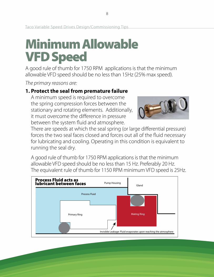
Minimum AllowableVFD SpeedA good rule of thumb for 1750 RPM applications is that the minimum allowable VFD speed should be no less than 15Hz (25% max speed). The primary reasons are:1. Protect the seal from premature failure
A minimum speed is required to overcome the spring compression forces between the stationary and rotating elements. Additionally, it must overcome the difference in pressure between the system fluid and atmosphere. There are speeds at which the seal spring (or large differential pressure) forces the two seal faces closed and forces out all of the fluid necessary for lubricating and cooling. Operating in this condition is equivalent to running the seal dry.
A good rule of thumb for 1750 RPM applications is that the minimum allowable VFD speed should be no less than 15 Hz. Preferably 20 Hz. The equivalent rule of thumb for 1150 RPM minimum VFD speed is 25Hz.
Primary Ring
Gland
Invisible Leakage: Fluid evaporates upon reaching the atmosphere
Pump Housing
Process Fluid
Process Fluid acts aslubricant between faces
Mating Ring

9
Taco Variable Speed Drives Design/Commissioning Tips
2. Below 15hz (25% max speed) is unlikely to move water out of the mechanical room According to the pump affinity laws, flow is proportional to speed and head is proportional to speed squared. When you run a pump at ¼ speed or 15hz, you can only generate 1/16 of the pumps head. i.e. 1/4 2 = 1/16 1/16th of the head is unlikely to even move the water out of the mechanical room.
Energy reduction at 1/4 speed = 1/4 3 or 1/64 of design HP. This is the realistic lower end of turn-down.
3. Specialty Pump Exceptions Some pumps such as vertical turbines require water to lubricate journals and bearings. Particularly vertical turbine pumps. The minimum speed must be set to move water up the height of the column and overcome any static head loss. There are times that this will be above the hz.

10
Taco Variable Speed Drives Design/Commissioning Tips
Establishing MinimumSystem Flow
The overall hydronic system and each of its major branches need a minimum amount of flow.
It is recommended to use a bypass with balancing valve or a three way valve at the end of each major zone for the following reasons:
• Prevents thermal stagnation.
• Increases the life of the pump by preventing dead-head or no-flow condition.
• Rule of thumb: Ensure there is at least 1/4 GPM per design HP to protect the pump at min speed.
Note: More flow will be required if you are trying to protect against dead head on a full speed situation.
Impellerat fullspeed
Impeller at1/4 speed

11
Taco Variable Speed Drives Design/Commissioning Tips
Use a Flow Meter for:
• Accurate Staging• End of Curve Protection• Shut Off Protection• Best Efficiency Control
Design tips for flow meters

12
Taco Variable Speed Drives Design/Commissioning Tips
Pump staging with flow• Here we show 2 pump parallel operation.
• Note the pumps are selected to allow the single pump curve to intersect the system curve.
• If the system flow increases beyond the single pump intersection point(a), the system will see a drop below the system setpoint and initiate the lag pump start.
Design System Head Curve
Design Point
Two Pump
Control DP
One Pump
A
Lag Pump Reject Zone
HEA
D
GPM

13
Taco Variable Speed Drives Design/Commissioning Tips
Liquid Flow SensorInstallation DetailNOTES:
• Refer to instruction manual for mechanical installation details.
• Orientation (Horizontally preferred).
• Locate for use in full pipe (Make sure to eliminate air).
• “A” Upstream — 10 pipe dia. length of straight rin pipe with no restrictions, enlargements, valves, couplings or other intrusions.
• “B” Upstream — 5 pipe dia. length of straight rin pipe with no restrictions, enlargements, valves, couplings or other intrusions.
Flow
Flow Sensor (Supplied)
Hot Tap (Supplied)
Nipple (Supplied)
2” NPT Coupling(By Field)
A B
Fair (Unacceptable if air is present)
Fair (Unacceptable if fluid contains sediment)
Best

14
Taco Variable Speed Drives Design/Commissioning Tips
Most systems are set up with the following problems:
• Incorrect pressure sensor installation
• Incorrect pressure sensor setpoint
• Air not bled out of sensor
• Control loops detuned to handle all situations
Common Problems

15
Differential Temperature• Delta-T lends itself to even more cost effective variable speed pumping.• The issues associate with placement and of Delta-T sensors is replaced with ease and simplicity of thermistors.• As the Delta-T falls below setpoint, the pumps would slow down.• As the Delta-T rises above setpoint, the pumps speed up.• Remember that BTUH = GPM x ∆T x 500
Temperature SensorTRP1 Series Sensor is a thermistor type 10K Ohms (Type III) sensor. The TRP1 Series is a stainless steel bullet probe which is 1/4” in diameter and 1” long with a 24” wire leads. Output: 10K Ohm @ 77˚F.
Taco Variable Speed Drives Design/Commissioning Tips

16
Taco, Inc.,1160 Cranston Street, Cranston, RI 02920 / (401) 942-8000 / Fax (401) 942-2360Taco (Canada) Ltd. 8450 Lawson Road, Unit #3, Milton, Ontario L9T 0J8 / (905) 564-9422 / Fax (905) 564-9436
www.taco-hvac.com
©Taco Catalog #300-28 Effective Date: 10/11/12Supersedes: 08/30/12 Printed in USA