1 Summary Sheet Session Number : Date : Subject Expert : 5 09.04.2007 Dr. M.C. Nataraja Professor...
48
1 Summary Sheet Session Number : Date : Subject Expert : 5 09.04.2007 Dr. M.C. Nataraja Dr. M.C. Nataraja Professor Department of Civil Engineering, Sri Jayachamarajendra College of Engineering, Mysore – 570 006. Phone:0821-2343521, 9880447742 E-mail: [email protected]
-
Upload
bartholomew-atkins -
Category
Documents
-
view
218 -
download
1
Transcript of 1 Summary Sheet Session Number : Date : Subject Expert : 5 09.04.2007 Dr. M.C. Nataraja Professor...

1
Summary SheetSession Number
:Date :
Subject Expert :
5 09.04.2007
Dr. M.C. NatarajaDr. M.C. Nataraja
Professor
Department of Civil Engineering,
Sri Jayachamarajendra College of Engineering,
Mysore – 570 006.
Phone:0821-2343521, 9880447742
E-mail: [email protected]

2
Design and Detailing of Counterfort Retaining wall
Dr. M.C. NATARAJA

3
• When H exceeds about 6m,• Stem and heel thickness is more• More bending and more steel• Cantilever-T type-Uneconomical• Counterforts-Trapezoidal section• 1.5m -3m c/c
Counterfort Retaining wall
CRW
CF
Base Slab
Stem

4
Parts of CRW• Same as that of Cantilever Retaining wall Plus
Counterfort
Stem
Toe Heel
Base slab
Counterforts
Cross section Plan

5
• The stem acts as a continuous slab • Soil pressure acts as the load on the
slab. • Earth pressure varies linearly over
the height• The slab deflects away from the
earth face between the counterforts• The bending moment in the stem is
maximum at the base and reduces towards top.
• But the thickness of the wall is kept constant and only the area of steel is reduced.
Design of Stem
BF
p=Kaγh

6
Maximum Bending moments for stem
Maximum +ve B.M= pl2/16 (occurring mid-way between counterforts)andMaximum -ve B.M= pl2/12 (occurring at inner face of counterforts)
Where ‘l’ is the clear distance between the counterforts and ‘p’ is the intensity of soil pressure
l
p+
-

7
Design of Toe Slab
The base width=b =0.6 H to 0.7 HThe projection=1/3 to 1/4 of base width. The toe slab is subjected to an upward soil
reaction and is designed as a cantilever slab fixed at the front face of the stem.
Reinforcement is provided on earth face along the length of the toe slab.
In case the toe slab projection is large i.e. > b/3, front counterforts are provided above the toe slab and the slab is designed as a continuous horizontal slab spanning between the front counterforts.
b
H

8
The heel slab is designed as a continuous slab spanning over the counterforts and is subjected to downward forces due to weight of soil plus self weight of slab and an upward force due to soil reaction.
Maximum +ve B.M= pl2/16 (mid-way between counterforts)AndMaximum -ve B.M= pl2/12 (occurring at counterforts)
Design of Heel Slab
BF

9
Design of Counterforts• The counterforts are subjected to
outward reaction from the stem. • This produces tension along the
outer sloping face of the counterforts. • The inner face supporting the stem is
in compression. Thus counterforts are designed as a T-beam of varying depth.
• The main steel provided along the sloping face shall be anchored properly at both ends.
• The depth of the counterfort is measured perpendicular to the sloping side.
TC
d

10
Behaviour of Counterfort RW
-M
-M
TOE
COUNTERFORT
+M
+M
STEM
HEEL SLAB
Important points
•Loads on Wall
•Deflected shape
•Nature of BMs
•Position of steel
•Counterfort details

11
PROBLEM-Counterfort Retaining Wall
• A R.C.C. retaining wall with counterforts is required to support earth to a height of 7 m above the ground level. The top surface of the backfill is horizontal. The trial pit taken at the site indicates that soil of bearing capacity 220 kN/m2 is available at a depth of 1.25 m below the ground level. The weight of earth is 18 kN/m3 and angle of repose is 30°. The coefficient of friction between concrete and soil is 0.58. Use concrete M20 and steel grade Fe 415. Design the retaining wall.
12
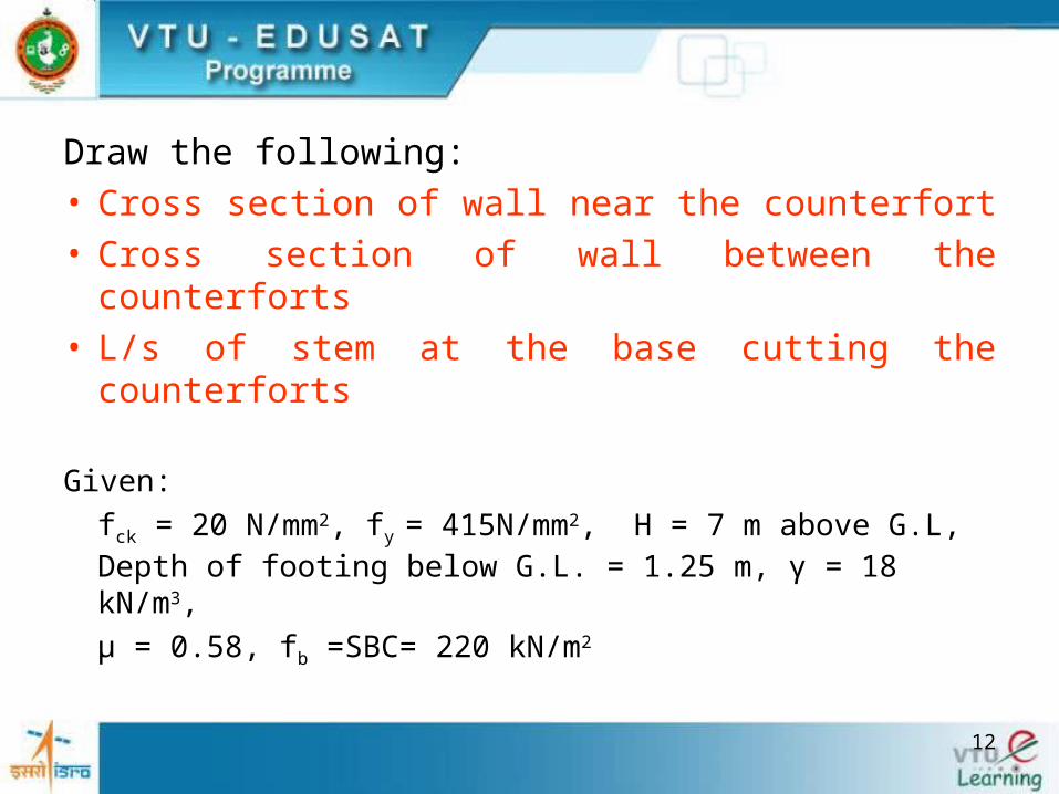
Draw the following:• Cross section of wall near the counterfort • Cross section of wall between the counterforts• L/s of stem at the base cutting the counterforts
Given:
fck = 20 N/mm2, fy = 415N/mm2, H = 7 m above G.L, Depth of footing below G.L. = 1.25 m, γ = 18 kN/m3,
μ = 0.58, fb =SBC= 220 kN/m2

13
a. Proportioning of Wall Components
Coefficient of active pressure = ka = 1/3
Coefficient of passive pressure= kp = 3
The height of the wall above the base
= H = 7 + 1.25 = 8.25 m.
Base width = 0.6 H to 0.7 H
(4.95 m to 5.78 m), Say b = 5.5 m
Toe projection = b/4 = 5.5/4 = say 1 .2 m
Assume thickness of vertical wall = 250 mm
Thickness of base slab = 450 mm
H
b=5.5 m
1.25 m
h1= 7 m

14
Spacing of counterforts
l = 3.5 (H/γ)0.25 = 3.5 (8.25/18)0.25 = 2.88 m c/c spacing = 2.88 + 0.40 = 3.28 m say 3 m
Provide counterforts at 3 m c/c.
Assume width of counterfort = 400 mm
clear spacing provided = l = 3 - 0.4 = 2.6 m
l

15
4.05m
h=7.8 m
θ
d
250 mm
1.2 m
b=5.5 m
H=8.25 mh1=7 m
1.25m
CF: 3m c/c, 400 mm
T
Details of wall

16
Sr.No.
Description of loads Loads in kN
Dist. ofe.g. from
T in m
Moment about
T in kN-m
1Weight of stem
W1
25x0.25x1x7.8= 48.75
1.2 + 0.25/2=1.325 64.59
2Weight of base
slab W2
25x5.5x1x0.45= 61.88 5.5/2 =2.75 170.17
3Weight of earth
over heel slab W3
18x4.05x1x7.8= 568.62
1.45 +4.05/2= 3.475
1975.95
Total ΣW = 679.25 ΣW =2210.71
b. Check Stability of Wall

17
A B C D
H8250
250 mm
1200 mm 4050 mm
450
Df= 1250
ΣW
PA
R
eX b/2T
W3W1
W2
PA
Pressure distribution
Cross section of wall-Stability analysis
b/3
kaH
H/3
h1= 7000

18
Stability of walls
Horizontal earth pressure on full height of wall
= Ph = kaH2 /2 =18 x 8.252/(3 x 2) = 204.19 kN
Overturning moment = M0
= Ph x H/3 = 204.19 x 8.25/3 = 561.52 kN.m.Factor of safety against overturning
= ∑ M / M0 = 2210.71/561.52 = 3.94 > 1.55 safe.

19
Check for sliding
Total horizontal force tending to slide the wall
= Ph = 204.19 kN
Resisting force = ∑µ.W = 0.58 x 679.25
= 393.97 kN
Factor of safety against sliding
= ∑µ.W / Ph = 393.97/204.19
= 1.93 > 1.55 ... safe.

20
Check for pressure distribution at base
Let x be the distance of R from toe (T), x = ∑ M / ∑ W = 2210.71 -561.52 /679.25 = 2.43 m Eccentricity=e = b/2 - x = 5.5/2 - 2.43 = 0.32 < b/6 (0.91m)Whole base is under compression.
Maximum pressure at toe= pA = ∑W / b ( 1+6e/b) = 679.25/5.5 ( 1+ 6*0.32/5.5)= 166.61 kN/m2 < f b (i.e. SBC= 220 kN/m2)
Minimum pressure at heel= pD = 80.39 kN/m2 compression.

21
Intensity of pressure at junction of stem with toe i.e. under B
= pB = 80.39 + (166.61 - 80.39) x 4.3/5.5 = 147.8kN/m2
Intensity of pressure at junction of stem with heel i.e. under C
=Pc= 80.39 + (166.61 - 80.39) x 4.05/5.5 = 143.9 kN/m2

22
80.39kN/m2166.61
kN/m2143.9147.8153.9
A B C D
H8250
250 mm
1200 mm
5500 mm
4050 mm
450
1250
ΣW
PA
R
eX b/2T

23
b) Design of Toe slab
Max. BMB = psf x (moment due to soil pressure - moment due to wt. of slab TB]
= 1.5 [147.8 x 1.22/2 + (166.61 - 147.8) x 1.2 (2/3 x 1.2)-(25x 1.2 x 0.45 x 1.2/2) =174.57 kN-m.
Mu/bd2= 1.14 < 2.76, URS

24
To find steel
pt=0.34% <0.96%, A st =1326 mm2, # 16 @150 However, provide # 16 @110 from shear considerations.
Area provided =1827 mm2 , pt=0.47%Development length= 47 x 16=750 mmDistribution steel = 0.12 x 1000 x 450/100 = 540 mm2
Provide #12 mm at 200 mm c/c. Area provided = 565 mm2
b) Design of Toe slab- Contd.,

25
Check for ShearCritical section for shear: At distance d (= 390 mm)
from the face of the toe pE = 80.39 + (166.61 - 80.39) (4.3 + 0.39)/5.5
= 153.9kN/m2
Net vertical shear = (166.61 + 153.9) x 0.81/2 - (25 x 0.45 x 0.81)
=120.7 kN. Net ultimate shear = Vu.max = 1.5 x 120.7 =181.05
kN.ζv= 181.05x 1000/1000x390 =0.46 MPapt = 100 x 1827/ (1000 x 390) = 0.47 %ζuc = 0.36 + (0.48 - 0.36) x 0.22/0.25
= 0.47N/mm2 > ζvsafe
d

26
-M
-M
TOE
COUNTERFORT
+M
+M
STEM
HEEL SLAB
Counterfort RW

27
Continuous slab. Consider 1 m wide strip near the outer edge D The forces acting near the edge areDownward wt. of soil=18x7.8xl= 140.4 kN/mDownward wt. of heel slab = 25 x 0.45 x 1= 11.25 kN/mUpward soil pressure 80.39 kN/m2= 80.39 x 1= 80.39 kN/m Net down force at D= 140.4 + 11.25 - 80.39 = 71.26 kN/m Also net down force at C = 140.4 + 11.25 - 143.9 = 7.75 kN/m
Negative Bending Moment for heel at junction of counterfort
Mu= (psf) pl2 /12 = 1.5 x 71.26 x 2.62/12 = 60.2 kN-m (At the junction of CF)
(c) Design of Heel Slab

28
71.26 kN/m
7.75 kN/m
DC
Forces on heel slab
80.39kN/m2166.61
kN/m2143.9147.8153.9
5500 mm

29
To find steel
Mu/bd2=60.2x106/(1000x3902)= 0.39 < 2.76, URS To find steelpt=0.114% <0.12%GA (Min. steel), <0.96%(pt,lim.) Provide 0.12% of GA
Ast= 0.12x1000x450/100 = 540 mm2
Provide # 12 mm @ 200 mm c/c, Area provided = 565 mm2
pt= 100 x 565/ (1000 x 390) = 0.14 %

30
Maximum shear = Vu,max = 1.5 x 71.26 x 2.6/2 = 139 kNFor Pt, = 0.14 % and M20 concrete, ζuc= 0.28 N/mm2
ζv= Vumax/bd =0.36 N/mm2 , ζuc < ζv, Unsafe, Hence shear steel is needed
Using #8 mm 2-legged stirrups,Spacing=0.87x415x100/[(0.36-0.28)x1000] = 452 mm < (0.75 x 390 = 290 mm or 300 mm ) Provide #8 mm 2-legged stirrups at 290 mm c/c.
Provide for 1m x 1m area as shown in figure
Check for shear (Heel slab)

31
A B C1200 mm
4050 mm
450
1250
R
eX b/2
26003000
4050 mm
C D
SFD
Net down force dia.
TOE
HEEL
139
71.28 kN/m
7.75 kN/m
x1
y1Shear analysis and Zone of shear steel
Area for stirrups

32
Area of steel for +ve moment(Heel slab)
Maximum +ve ultimate moment = psf x pl2/16= 3/4 Mu = 0.75 x 60.2= 45.15 kN-m.
Mu/bd2=Very small and hence provide minimum steel.
Ast,min= 540 mm2
Provide # 12 mm bars at 200 mm c/c. Area provided = 565 mm2 > 540 mm2

33
Check the force at junction of heel slab with stemThe intensity of downward force decreases due to
increases in upward soil reaction. Consider m width of the slab at C
Net downward force= 18 x 7.8 +25 x 0.45 - 143.9 = 7.75 kN/m. Provide only minimum reinforcement.
Distribution steel
Ast = 0.12 x 1000 x 450/100 = 540 mm2 Using # 12 mm bars, spacing = 1000 x 113/468 = 241 mm. Provide # 12 mm at 200 mm c/c.Area provided = 565 mm2
34
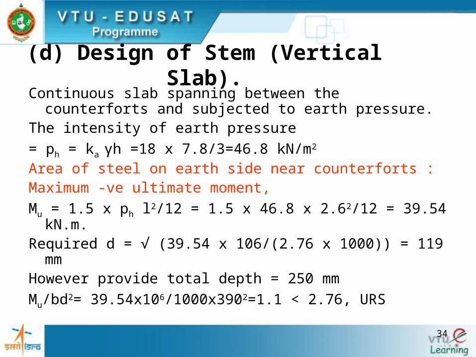
(d) Design of Stem (Vertical Slab).Continuous slab spanning between the counterforts and
subjected to earth pressure.The intensity of earth pressure
= ph = ka γh =18 x 7.8/3=46.8 kN/m2
Area of steel on earth side near counterforts : Maximum -ve ultimate moment,
Mu = 1.5 x ph l2/12 = 1.5 x 46.8 x 2.62/12 = 39.54 kN.m. Required d = √ (39.54 x 10⁶/(2.76 x 1000)) = 119 mmHowever provide total depth = 250 mm
Mu/bd2= 39.54x10⁶/1000x3902=1.1 < 2.76, URS

35
To find steel: Pt=0.34% <0.96%, Ast=646 mm2, #12 mm @ 170 mm c/c, However provide #12 mm @ 110 mm c/c, Area provided = 1027.27 mm2,Pt= 0.54 %.
As the earth pressure decreases towards the top, the spacing of the bars is increased with decrease in height.
Max.ult. shear = Vumax = 1.5 x 46.8 x 2.6/2 = 91.26 kNFor Pt, = 0.54 % and M20 concrete ζuc= 0.5 N/mm2
ζv= Vumax/bd =91.28 x1000/(100X190)=0.48 N/mm2,
Shear steel is not needed and hence safe.

36
At any section at any depth h below the top, the total horizontal earth pressure acting on the counterfort
= 1/2 kay h2x c/c distance between counterfort= 18 x h2 x 3 x 1/6 = 9 h2
B.M. at any depth h = 9h2xh/3 = 3h3
B.M. at the base at C= 3 x 7.83 = 1423.7 kN.m. Ultimate moment = Mu= 1.5 x 1423.7 = 2135.60 kN.m.
Counterfort acts as a T-beam. Even assuming rectangular section,d =√(2135.6 x 106(2.76 x 400)) = 1390 mm
(e) Design of Counterfort

37
The effective depth is taken at right angle to the reinforcement.
tan θ = 7.8/4.05 =1.93, θ = 62.5°,
d = 4050 sin θ - eff. cover
= 3535 mm > > 1390 mm
Mu/bd2=2135.6x106/(400x35352) =0.427, pt=0.12%, Ast=1696mm2
Check for minimum steel 4.05m
h =7.8 m
θd

38
Ast.min = 0.85 bd/fy = 0.85 x 400 x 3535/415 = 2896 mm2
Provided 4- # 22 mm + 4 - # 22 mm, Area provided = 3041 mm2
pt = 100 x 3041/(400 x 3535) = 0.21 %
The height h where half of the reinforcement can be curtailed is approximately equal to √H= √7.8=2.79 m
Curtail 4 bars at 2.79-Ldt from top i.e, 2.79-1.03 =1.77m from top.

39
Design of Horizontal TiesThe direct pull by the wall on counterfort for 1 m height at
base
= kaγh x c/c distance =1/3x18 x 7.8 x 3 = 140.4 kNArea of steel required to resist the direct pull= 1.5 x 140.4 x 103/(0.87 x 415) = 583 mm2 per m height.
Using # 8 mm 2-legged stirrups, Ast = 100 mm2
spacing = 1000 x 100/583 = 170 mm c/c. Provide # 8 at 170 mm c/c.Since the horizontal pressure decreases with h, the spacing
of stirrups can be increased from 170 mm c/c to 450 mm c/c towards the top.

40
Design of Vertical Ties
The maximum pull will be exerted at the end of heel slab where the net downward force = 71.26 kN/m.
Total downward force at D= 71.26 x c/c distance bet. CFs = 71.28 x 3 = 213.78 kN.
Required Ast = 1.5 x 213.78 x 103/(0.87 x 415) = 888 mm2
Using # 8 mm 2-legged stirrups , Ast = 100 mm2
spacing = 1000 x 100/888 = 110 mm c/c.
Provide # 8 mm 2-legged stirrups at 110 mm c/c.Increase the spacing of vertical stirrups from 110 mm c/c to
450 mm c/c towards the end C

41
DRAWING AND DETAILING
COUNTERFORT RETAINING WALL
42
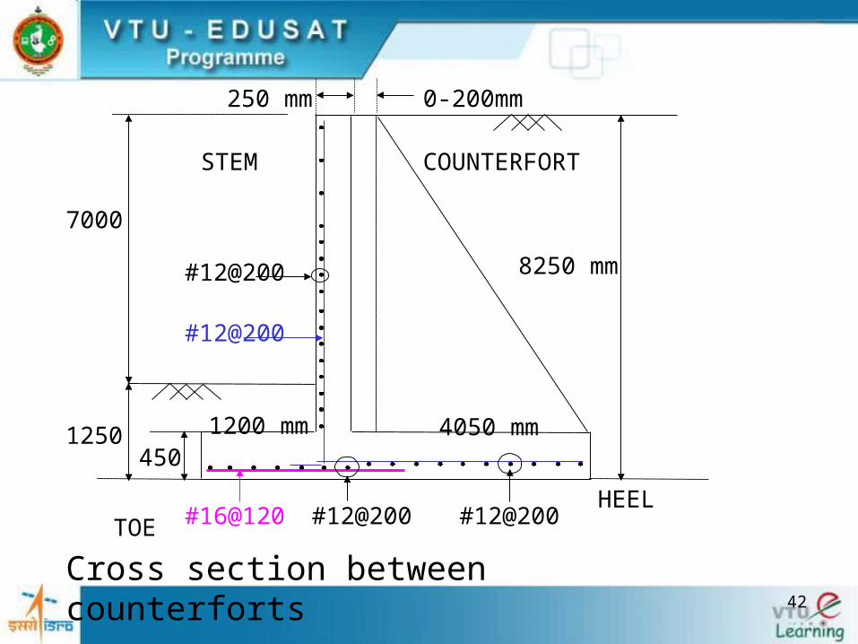
250 mm
1200 mm 4050 mm450
1250
#16@120 #12@200 #12@200
#12@200
#12@200
8250 mm
7000
Cross section between counterforts
0-200mm
STEM COUNTERFORT
TOE HEEL

43
250 mm
1200 mm450
1250
#16@120 #12@200
8 - # 22
#12@200
#8@170-450, HS
#8@110-450, VS
#12@ 110-300
#12@200
#12@4008-#22 1.77m
8250
Cross section through counterforts

44
Section through stem at the junction of Base slab.
Backfill
With straight bars
0.3l
0.25 l
Backfill
With cranked bars
STEMSTRAIGHT BARS

45
Cross section of heel slab
BackfillBackfill

46
Examination Problems
July 2006
• Single bay Fixed Portal Frame
• Combined footing (Beam and slab type)
December 2006
• T-shaped Cantilever Retaining wall
• Combined footing (Type not mentioned)

47
Exam Problem (Dec. 2006)Design a T shaped cantilever retaining wall to retain earth
embankment 3.2 m high above the ground level. The unit weight of the earth is 18 kN/m2 and its angle of repose is 30 degrees. The embankment is horizontal at it top. The SBC of soil is 120 kN/m2 and the co-efficient of friction between soil and concrete is 0.5. Use M20 concrete and Fe 415 steel. Draw the following to a suitable scale:
1. Section of the retaining wall2. Reinforcement details at the inner face of the stem.
60 MarksData: h1=3.2 m, µ=0.5, γ=18 kN/m2, ө=30º, SBC= 120
kN/m2,
M20 Concrete and Fe 415 steelFind H= h1 + Df

48
![Monash IPEG 2019 (Nataraja)[197350] University Title Monash IPEG 2019 (Nataraja)[197350].pdf Author JQ Narvaez Created Date 10/3/2017 9:45:10 AM ...](https://static.fdocuments.us/doc/165x107/5adb2bf57f8b9a6d318dbc3b/monash-ipeg-2019-nataraja197350-university-title-monash-ipeg-2019-nataraja197350pdf.jpg)