1 SERIES Single one Mini-Split Inverter System MMLW19A1NA ...
24
SUBMITTAL © 2018 Ingersoll Rand All Rights Reserved TAG: _________________________________ 18 SERIES Single Zone Mini-Split Inverter System M4MLW1809A1N0A M4TLS1809A11NA M4MLW1809A-SUB-1A Specifications MODEL - Heat Pump Only RATED Volts/PH Frequency (Hz) Rated Cooling / Heating Capacity (Btu/h): Minimum Cooling Capacity (@95F) (Btu/h): Maximum Cooling Capacity (@95F) (Btu/h): Minimum Heating Capacity (@47F) (Btu/h): Maximum Heating Capacity (@47F) (Btu/h): Maximum Heating Capacity (@17F) (Btu/h): Total Capacity (W) (High/Standard/Low): Rated Power Input (W) Nominal Input Current (A) SEER / HSPF Air Flow Volume (CFM) (H/M/L) Dehumidifying Volume (pt./h) EER (Btu/W hr)/COP Indoor Unit Fan Motor Speed (r/min) (SH/H/M/L) Fan Motor RLA(A) Evaporator Pipe Diameter (inch) Row Fin Gap (inch) Coil length (L) x depth (D) x coil width (W) (inch) Output of Swing Motor (W) Fuse (A) Sound Power Level dB (A)(SH/H/M/L) Sound PRESSURE Level dB (A)(SH/H/M/L) 1 Uncrated Dimension (W/H/D) (inch) Crated Dimension of Package (L/W/H) (inch) Net Weight /Gross Weight (lbs) Outdoor Unit Compressor Type Compressor Oil L.R.A. (A) Compressor RLA(A) Compressor Power Input(W) Throttling Method Working Temp Range (°F) Condenser Pipe Diameter (inch) Row Fin Gap (inch) Coil length (l) x depth (D) x coil width (W) (inch) Fan Motor Speed (rpm) Output of Fan Motor (W) Fan Motor RLA (A) Air Flow Volume of Outdoor Unit (CFM) Fan Diameter (inch) Defrosting Method Sound Power Level dB (A) Sound PRESSURE Level dB (A) 1 Uncrated Dimension (W/H/D) (inch) Crated Dimension of Package (W/L/H) (inch) Net Weight /Gross Weight (lbs) Refrigerant Charge (oz) MCA MOP Connection Pipe Refrigerant additional charge(oz/ft) Outer Diameter Liquid Pipe (inch) Outer Diameter Gas Pipe (inch) Max Height Distance (ft) Max Length Distance (ft) 1 Sound PRESSURE Level @ 3.3 ft. dB(A) M4MLW1809A / M4TLS1809A Cooling Heating 208 / 230 / 1 60Hz 9200 10000 3100 - 9600 - - 3100 - 12000 - 5800 2814 / 2625 / 908 3517 / 2784 / 909 850 850 4.0 3.8 18.5 10.2 540 / 490 / 410 / 290 1.7 10.6 3.28 M4MLW1809A1N0 1350 / 1200 / 1050 / 750 1350 / 1200 / 1050 / 850 0.22 Aluminum Fin-Copper Tube 0.2 2 - 0.055 23.0 x 0.9 x 10.5 1.5 3.15 53 / 49 / 45 / 39 43 / 38 / 34 / 28 31.1 x 10.8 x 7.9 34.1 x 10.7 x 14.4 20.9 / 25.4 M4TLS1809A11N Rotary RB68EP (POE Oil) 35.0 6.60 1020 EEV 0 - 115 -13 - 75 Aluminum Fin-Copper Tube 0.28 1 - 0.055 28 × 0.7 × 20 900 30 0.36 1600 15.7 Automatic Defrosting 62 52 30.6 x 21.3 x 12.6 32.4 x 13.3 x 23.4 63.9 / 69.4 24.7 9.0 15.0 0.22 1/4 3/8 66 98
Transcript of 1 SERIES Single one Mini-Split Inverter System MMLW19A1NA ...

SUBMITTAL
© 2018 Ingersoll Rand All Rights Reserved
TAG: _________________________________
18 SERIES
Single Zone Mini-SplitInverter System
M4MLW1809A1N0AM4TLS1809A11NA
M4MLW1809A-SUB-1A
Specifications
MODEL - Heat Pump Only
RATED Volts/PHFrequency (Hz)Rated Cooling / Heating Capacity (Btu/h):Minimum Cooling Capacity (@95F) (Btu/h):Maximum Cooling Capacity (@95F) (Btu/h):Minimum Heating Capacity (@47F) (Btu/h):Maximum Heating Capacity (@47F) (Btu/h):Maximum Heating Capacity (@17F) (Btu/h):Total Capacity (W) (High/Standard/Low):Rated Power Input (W)Nominal Input Current (A)SEER / HSPF Air Flow Volume (CFM) (H/M/L)Dehumidifying Volume (pt./h)EER (Btu/W hr)/COP
Indoor UnitFan Motor Speed (r/min) (SH/H/M/L)Fan Motor RLA(A)EvaporatorPipe Diameter (inch)Row Fin Gap (inch)Coil length (L) x depth (D) x coil width (W) (inch)Output of Swing Motor (W)Fuse (A)Sound Power Level dB (A)(SH/H/M/L)Sound PRESSURE Level dB (A)(SH/H/M/L) 1Uncrated Dimension (W/H/D) (inch)Crated Dimension of Package (L/W/H) (inch)Net Weight /Gross Weight (lbs)
Outdoor UnitCompressor TypeCompressor OilL.R.A. (A)Compressor RLA(A)Compressor Power Input(W)Throttling MethodWorking Temp Range (°F)CondenserPipe Diameter (inch)Row Fin Gap (inch)Coil length (l) x depth (D) x coil width (W) (inch)Fan Motor Speed (rpm)Output of Fan Motor (W)Fan Motor RLA (A)Air Flow Volume of Outdoor Unit (CFM)Fan Diameter (inch)Defrosting MethodSound Power Level dB (A)Sound PRESSURE Level dB (A) 1Uncrated Dimension (W/H/D) (inch)Crated Dimension of Package (W/L/H) (inch)Net Weight /Gross Weight (lbs)Refrigerant Charge (oz)MCAMOP
Connection PipeRefrigerant additional charge(oz/ft)Outer Diameter Liquid Pipe (inch)Outer Diameter Gas Pipe (inch)Max Height Distance (ft)Max Length Distance (ft)
1 Sound PRESSURE Level @ 3.3 ft. dB(A)
M4MLW1809A / M4TLS1809ACooling Heating
208 / 230 / 1 60Hz
9200 10000 3100 - 9600 - - 3100- 12000- 5800
2814 / 2625 / 908 3517 / 2784 / 909 850 850 4.0 3.8 18.5 10.2
540 / 490 / 410 / 2901.7
10.6 3.28
M4MLW1809A1N01350 / 1200 / 1050 / 750 1350 / 1200 / 1050 / 850
0.22Aluminum Fin-Copper Tube
0.22 - 0.055
23.0 x 0.9 x 10.51.53.15
53 / 49 / 45 / 3943 / 38 / 34 / 2831.1 x 10.8 x 7.9 34.1 x 10.7 x 14.4
20.9 / 25.4
M4TLS1809A11NRotary
RB68EP (POE Oil)35.06.601020EEV
0 - 115 -13 - 75Aluminum Fin-Copper Tube
0.281 - 0.055
28 × 0.7 × 20 90030
0.36160015.7
Automatic Defrosting6252
30.6 x 21.3 x 12.632.4 x 13.3 x 23.4
63.9 / 69.424.7 9.015.0
0.221/43/86698

Unit Dimensions
W D
H
3 1/262 1/8 2 1/8
6 5/8 18 3/16 6 5/16
Φ2 3/16
Φ2 3/16 Φ2 3/16
Φ2 3/16
4 11/16 21 5/16 7 1/4
3 5/165
1 3/8 1 3/8
MODEL W H D09K 31 1/8 10 7/8 7 7/812K 33 1/4 11 3/8 8 1/4
Unit:inch
09K
12K
The dimensions in these drawings are rounded according to standard measurement.
Indoor Unit Dimensions
9K-12K Indoor Units

Unit Dimensions
Unit:inch
30 9/16
21 1
/4
12 5/8
82
11 1
/4
20
10 1/8
9K-12K Outdoor Units
Outdoor Unit Dimensions
The dimensions in these drawings are rounded according to standard measurement.

Air Velocity Patterns for High WallMax Horizontal Distance
Unit: ft. (m)Model Cooling Mode Heating Mode
M4MLW1809A 13.1 (4) 13.1 (4)
Clearance Requirements
valve cover
Space to the wal l
Space to the ceiling
Space to the wall
Space to the wall
Air outlet side Space to the floor
or moreor more
6 in. or more 6 in. or more
12 in. or more
20 in. or more
20 in
. or m
ore
12 in. o
r more
or m
ore .ni97
or more
Space to the obstruction
Air outlet side
Space to the wall
Air inlet side
The dimensions of the space necessary for correct installation of the appliance including the minimum permissible distances to adjacent structures
6 in.
66in.
118 in.
NOTE: The maximum recommended height from the floor to the bottom of the indoor unit is 11.5 ft. (3.5 m).

Performance Data
Capacities in these performance tables reflect normal operation at the temperatures indicated. See specification tables for certified values under prescribed test conditions.
TC* SHC** TC SHC TC SHC TC SHC0 4500 3600 4800 3800 5400 4300 5600 450010 5400 4300 5700 4600 6400 5100 6700 530020 6100 4900 6500 5300 7400 6000 7700 620030 6500 5200 6900 5500 7800 6200 8100 650040 6700 5400 7100 5700 8000 6400 8400 670050 7000 5600 7400 5900 8400 6700 8700 700060 7700 6300 8300 6700 9000 7300 9800 800065 8300 6800 8800 7200 9500 7800 10300 840070 8600 7100 9200 7500 9800 8000 10500 860075 8600 7000 9100 7500 9700 8000 10400 850080 8400 6900 8900 7400 9600 7900 10300 850085 8200 6800 8700 7200 9500 7900 10200 840090 7900 6600 8500 7100 9300 7700 10000 830095 7700 6500 8200 6900 9000 7600 9800 8300100 7500 6300 8000 6700 8900 7500 9600 8100105 7300 6100 7800 6600 8700 7300 9400 7900110 7100 6000 7600 6400 8500 7200 9200 7800115 6900 5800 7400 6300 8300 7100 9000 7700
M4TLS1809A1/M4MLW1809A1 ‐ Heating Mode Performance Data
TC* TC TC TC‐13 4500 4400 4300 4200‐5 4900 4800 4700 46000 5300 5300 5200 50005 5600 5500 5400 530010 5900 5800 5700 550015 6000 5900 5800 570020 6300 6200 6100 600025 7000 6900 6700 660030 7500 7400 7300 710035 8100 8000 7800 770040 8700 8600 8500 830045 9600 9500 9300 910050 9800 9600 9400 920055 10000 9800 9600 940060 10200 10000 9800 960065 10300 10200 10000 970070 10500 10300 10100 980075 10600 10400 10200 9900
M4TLS1809A1/M4MLW1809A1 ‐ Cooling Mode Performance DataOutdoor
Ambient Air Temperature
(°F)
Indoor Entering Air Temperature (Dry Bulb/Wet Bulb)
Outdoor Ambient Air Temperature
(°F)
Indoor Entering Air Temperature
68/57°F 73/61°F 80/67°F 82/68°F
68°F 73°F 80°F 82°F
*Total Capacity **Sensible Heat Capacity
*Total Capacity

01/18
The manufacturer has a policy of continuous product and product data improvement and it reserves the right
to change design and specifications without notice.
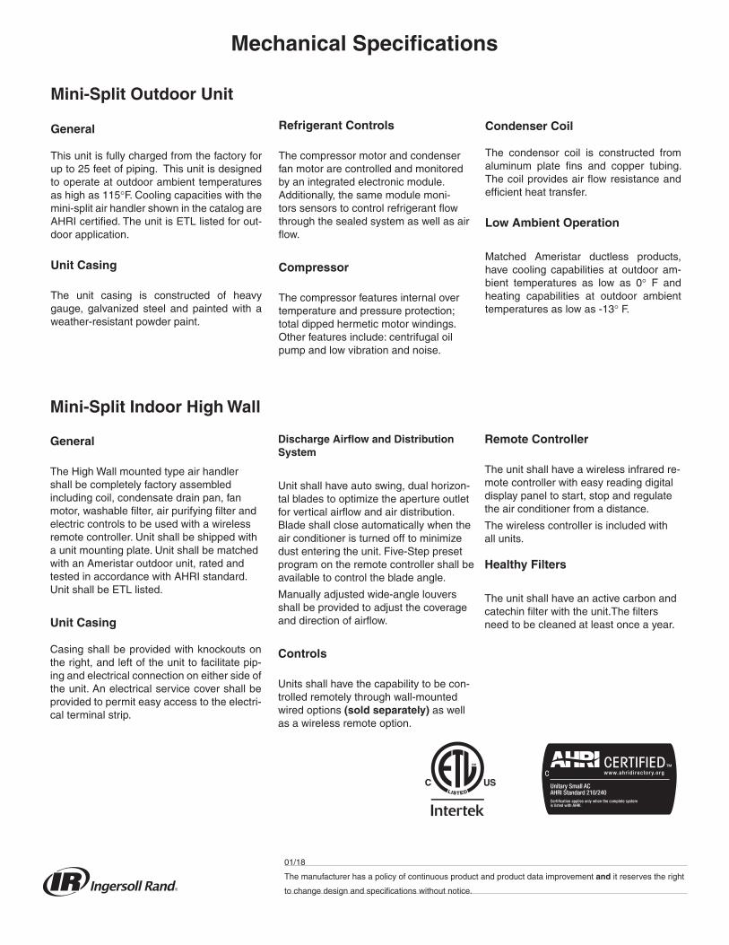
Mechanical Specifications
Mini-Split Outdoor Unit
General
This unit is fully charged from the factory for up to 25 feet of piping. This unit is designed to operate at outdoor ambient temperatures as high as 115°F. Cooling capacities with the mini-split air handler shown in the catalog are AHRI certified. The unit is ETL listed for out-door application.
Unit Casing
The unit casing is constructed of heavy gauge, galvanized steel and painted with a weather-resistant powder paint.
Refrigerant Controls
The compressor motor and condenser fan motor are controlled and monitored by an integrated electronic module. Additionally, the same module moni-tors sensors to control refrigerant flow through the sealed system as well as air flow.
Compressor
The compressor features internal over temperature and pressure protection; total dipped hermetic motor windings. Other features include: centrifugal oil pump and low vibration and noise.
Condenser Coil
The condensor coil is constructed from aluminum plate fins and copper tubing. The coil provides air flow resistance and efficient heat transfer.
Low Ambient Operation
Matched Ameristar ductless products, have cooling capabilities at outdoor am-bient temperatures as low as 0° F and heating capabilities at outdoor ambient temperatures as low as -13° F.
Mini-Split Indoor High Wall
General
The High Wall mounted type air handler shall be completely factory assembled including coil, condensate drain pan, fan motor, washable filter, air purifying filter and electric controls to be used with a wireless remote controller. Unit shall be shipped with a unit mounting plate. Unit shall be matched with an Ameristar outdoor unit, rated and tested in accordance with AHRI standard. Unit shall be ETL listed.
Unit Casing
Casing shall be provided with knockouts on the right, and left of the unit to facilitate pip-ing and electrical connection on either side of the unit. An electrical service cover shall be provided to permit easy access to the electri-cal terminal strip.
Discharge Airflow and Distribution System
Unit shall have auto swing, dual horizon-tal blades to optimize the aperture outlet for vertical airflow and air distribution. Blade shall close automatically when the air conditioner is turned off to minimize dust entering the unit. Five-Step preset program on the remote controller shall be available to control the blade angle.
Manually adjusted wide-angle louvers shall be provided to adjust the coverage and direction of airflow.
Controls
Units shall have the capability to be con-trolled remotely through wall-mounted wired options (sold separately) as well as a wireless remote option.
Remote Controller
The unit shall have a wireless infrared re-mote controller with easy reading digital display panel to start, stop and regulate the air conditioner from a distance.
The wireless controller is included with all units.
Healthy Filters
The unit shall have an active carbon and catechin filter with the unit.The filters need to be cleaned at least once a year.

SUBMITTAL
© 2018 Ingersoll Rand All Rights Reserved
TAG: _________________________________
18 SERIES
Single Zone Mini-SplitInverter System
M4MLW1812A1N0AM4TLS1812A11NA
M4MLW1812A-SUB-1A
Specifications
MODEL - Heat Pump Only
RATED Volts/PHFrequency (Hz)Rated Cooling / Heating Capacity (Btu/h):Minimum Cooling Capacity (@95F) (Btu/h):Maximum Cooling Capacity (@95F) (Btu/h):Minimum Heating Capacity (@47F) (Btu/h):Maximum Heating Capacity (@47F) (Btu/h):Maximum Heating Capacity (@17F) (Btu/h):Total Capacity (W) (High/Standard/Low):Rated Power Input (W)Nominal Input Current (A)SEER / HSPF Air Flow Volume (CFM) (H/M/L)Dehumidifying Volume (pt./h)EER (Btu/W hr)/COP
Indoor UnitFan Motor Speed (r/min) (SH/H/M/L)Fan Motor RLA(A)EvaporatorPipe Diameter (inch)Row Fin Gap (inch)Coil length (L) x depth (D) x coil width (W) (inch)Output of Swing Motor (W)Fuse (A)Sound Power Level dB (A)(SH/H/M/L)Sound PRESSURE Level dB (A)(SH/H/M/L) 1Uncrated Dimension (W/H/D) (inch)Crated Dimension of Package (L/W/H) (inch)Net Weight /Gross Weight (lbs)
Outdoor UnitCompressor TypeCompressor OilL.R.A. (A)Compressor RLA(A)Compressor Power Input(W)Throttling MethodWorking Temp Range (°F)CondenserPipe Diameter (inch)Row Fin Gap (inch)Coil length (l) x depth (D) x coil width (W) (inch)Fan Motor Speed (rpm)Output of Fan Motor (W)Fan Motor RLA (A)Air Flow Volume of Outdoor Unit (CFM)Fan Diameter (inch)Defrosting MethodSound Power Level dB (A)Sound PRESSURE Level dB (A) 1Uncrated Dimension (W/H/D) (inch)Crated Dimension of Package (W/L/H) (inch)Net Weight /Gross Weight (lbs)Refrigerant Charge (oz)MCAMOP
Connection PipeRefrigerant additional charge(oz/ft)Outer Diameter Liquid Pipe (inch)Outer Diameter Gas Pipe (inch)Max Height Distance (ft)Max Length Distance (ft)
1 Sound PRESSURE Level @ 3.3 ft. dB(A)
M4MLW1812A / M4TLS1812ACooling Heating
208 / 230 / 1 60Hz
12100 12900 3750 - 12500 - - 3924 - 14000 - 8100
3664 / 3525 / 1100 4103 / 3810 / 11501150 1250
5.1 5.5518.5 9.2
680 / 540 / 410 / 3303.0
10.4 3.05
M4MLW1812A1N01350 / 1200 / 1000 / 800 1350 / 1200 / 1000 / 900
0.31Aluminum Fin-Copper Tube
0.22 - 0.055
25.0 x 0.9 x 12.0 1.53.15
53 / 49 / 45 / 3943 / 39 / 35 / 2933.3 x 11.4 x 8.236.3 x 11.1 x 14.9
23.1 / 27.6
M4TLS1812A11NRotary
RB68EP (POE Oil)35.06.601020EEV
0 - 115 -13 - 75Aluminum Fin-Copper Tube
0.282 - 0.055
28 × 1.5 × 20 90030
0.37160015.7
Automatic Defrosting6353
30.6 x 21.3 x 12.632.4 x 14.1 x 23.4
69.4 / 75.031.8 9.015.0
0.221/43/86698

Unit Dimensions
Indoor Unit Dimensions
W D
H
3 1/262 1/8 2 1/8
6 5/8 18 3/16 6 5/16
Φ2 3/16
Φ2 3/16 Φ2 3/16
Φ2 3/16
4 11/16 21 5/16 7 1/4
3 5/165
1 3/8 1 3/8
MODEL W H D09K 31 1/8 10 7/8 7 7/812K 33 1/4 11 3/8 8 1/4
Unit:inch
09K
12K
9K-12K Indoor Units
The dimensions in these drawings are rounded according to standard measurement.

Unit Dimensions
Unit:inch
30 9/16
21 1
/4
12 5/8
82
11 1
/4
20
10 1/8
9K-12K Outdoor Units
Outdoor Unit Dimensions
The dimensions in these drawings are rounded according to standard measurement.

Air Velocity Patterns for High WallMax Horizontal Distance
Unit: ft. (m)Model Cooling Mode Heating Mode
M4MLW1812A 29.5 (9) 19.7 (6)
Clearance Requirements
valve cover
Space to the wal l
Space to the ceiling
Space to the wall
Space to the wall
Air outlet side Space to the floor
or moreor more
6 in. or more 6 in. or more
12 in. or more
20 in. or more
20 in
. or m
ore
12 in. o
r more
or m
ore .ni97
or more
Space to the obstruction
Air outlet side
Space to the wall
Air inlet side
The dimensions of the space necessary for correct installation of the appliance including the minimum permissible distances to adjacent structures
6 in.
66in.
118 in.
NOTE: The maximum recommended height from the floor to the bottom of the indoor unit is 11.5 ft. (3.5 m).

Performance Data
Capacities in these performance tables reflect normal operation at the temperatures indicated. See specification tables for certified values under prescribed test conditions.
TC* SHC** TC SHC TC SHC TC SHC0 6800 5400 7200 5700 7600 6400 7700 670010 7500 5900 7900 6300 8800 7100 8900 720020 8200 6500 8800 6900 10000 7800 10100 790030 9100 6900 9300 7500 11300 8400 11500 860040 9700 7300 10000 8000 11700 8800 12000 910050 10000 7800 10600 8400 11900 9200 12200 960055 10100 7900 10800 8500 12000 9300 12300 970060 10400 8100 11100 8700 12100 9500 12500 980065 11000 8600 11700 9100 12500 9700 12700 1020070 11400 8900 12100 9400 12800 9900 12900 1040075 11400 8900 12100 9400 12900 10100 13200 1040080 11100 8800 11900 9300 12900 10100 13200 1030085 10700 8500 11700 9100 12700 9900 13000 1020090 10500 8300 11400 8900 12400 9700 12800 1000095 10300 8100 11100 8700 12100 9500 12500 9800100 10100 7900 10800 8500 12000 9400 12300 9700105 9800 7800 10600 8300 11800 9300 12200 9500110 9600 7600 10300 8100 11600 9100 11900 9300115 9300 7400 10100 7900 11300 8900 11600 9100
M4TLS1812A1/M4MLW1812A1 ‐ Heating Mode Performance Data
TC* TC TC TC‐13 4500 4400 4300 4300‐10 5500 5300 5200 5200‐5 6400 6300 6100 61000 7300 7200 7000 70005 7700 7500 7300 730010 8100 7900 7700 770015 8300 8100 7900 790020 8700 8500 8300 820025 9600 9400 9200 910030 10300 10100 9900 980035 11000 10800 10600 1050040 11700 11500 11300 1120045 12600 12400 12100 1210050 13200 12900 12600 1260055 13400 13100 12800 1270060 13700 13300 13000 1300065 13900 13600 13300 1320070 14200 13800 13500 1340075 14400 14000 13700 13600
M4TLS1812A1/M4MLW1812A1 ‐ Cooling Mode Performance DataOutdoor
Ambient Air Temperature
(°F)
Indoor Entering Air Temperature (Dry Bulb/Wet Bulb)
Outdoor Ambient Air Temperature
(°F)
Indoor Entering Air Temperature
68/57°F 73/61°F 80/67°F 82/68°F
68°F 73°F 80°F 82°F
*Total Capacity **Sensible Heat Capacity
*Total Capacity

01/18
The manufacturer has a policy of continuous product and product data improvement and it reserves the right
to change design and specifications without notice.
Mechanical Specifications
Mini-Split Indoor High Wall
General
The High Wall mounted type air handler shall be completely factory assembled including coil, condensate drain pan, fan motor, washable filter, air purifying filter and electric controls to be used with a wireless remote controller. Unit shall be shipped with a unit mounting plate. Unit shall be matched with an Ameristar outdoor unit, rated and tested in accordance with AHRI standard. Unit shall be ETL listed.
Unit Casing
Casing shall be provided with knockouts on the right, and left of the unit to facilitate pip-ing and electrical connection on either side of the unit. An electrical service cover shall be provided to permit easy access to the electri-cal terminal strip.
Discharge Airflow and Distribution System
Unit shall have auto swing, dual horizon-tal blades to optimize the aperture outlet for vertical airflow and air distribution. Blade shall close automatically when the air conditioner is turned off to minimize dust entering the unit. Five-Step preset program on the remote controller shall be available to control the blade angle.
Manually adjusted wide-angle louvers shall be provided to adjust the coverage and direction of airflow.
Controls
Units shall have the capability to be con-trolled remotely through wall-mounted wired options (sold separately) as well as a wireless remote option.
Remote Controller
The unit shall have a wireless infrared re-mote controller with easy reading digital display panel to start, stop and regulate the air conditioner from a distance.
The wireless controller is included with all units.
Healthy Filters
The unit shall have an active carbon and catechin filter with the unit.The filters need to be cleaned at least once a year.
Mini-Split Outdoor Unit
General
This unit is fully charged from the factory for up to 25 feet of piping. This unit is designed to operate at outdoor ambient temperatures as high as 115°F. Cooling capacities with the mini-split air handler shown in the catalog are AHRI certified. The unit is ETL listed for out-door application.
Unit Casing
The unit casing is constructed of heavy gauge, galvanized steel and painted with a weather-resistant powder paint.
Refrigerant Controls
The compressor motor and condenser fan motor are controlled and monitored by an integrated electronic module. Additionally, the same module moni-tors sensors to control refrigerant flow through the sealed system as well as air flow.
Compressor
The compressor features internal over temperature and pressure protection; total dipped hermetic motor windings. Other features include: centrifugal oil pump and low vibration and noise.
Condenser Coil
The condensor coil is constructed from aluminum plate fins and copper tubing. The coil provides air flow resistance and efficient heat transfer.
Low Ambient Operation
Matched Ameristar ductless products, have cooling capabilities at outdoor am-bient temperatures as low as 0° F and heating capabilities at outdoor ambient temperatures as low as -13° F.

SUBMITTAL
© 2018 Ingersoll Rand All Rights Reserved
TAG: _________________________________
18 SERIES
Single Zone Mini-SplitInverter System
M4MLW1818A1N0AM4TLS1818A11NA
M4MLW1818A-SUB-1A
Specifications
MODEL - Heat Pump Only
RATED Volts/PHFrequency (Hz)Rated Cooling / Heating Capacity (Btu/h):Minimum Cooling Capacity (@95F) (Btu/h):Maximum Cooling Capacity (@95F) (Btu/h):Minimum Heating Capacity (@47F) (Btu/h):Maximum Heating Capacity (@47F) (Btu/h):Maximum Heating Capacity (@17F) (Btu/h):Total Capacity (W) (High/Standard/Low):Rated Power Input (W)Nominal Input Current (A)SEER / HSPF Air Flow Volume (CFM) (H/M/L)Dehumidifying Volume (pt./h)EER (Btu/W hr)/COP
Indoor UnitFan Motor Speed (r/min) (SH/H/M/L)Fan Motor RLA(A)EvaporatorPipe Diameter (inch)Row Fin Gap (inch)Coil length (L) x depth (D) x coil width (W) (inch)Output of Swing Motor (W)Fuse (A)Sound Power Level dB (A)(SH/H/M/L)Sound PRESSURE Level dB (A)(SH/H/M/L) 1Uncrated Dimension (W/H/D) (inch)Crated Dimension of Package (L/W/H) (inch)Net Weight /Gross Weight (lbs)
Outdoor UnitCompressor TypeCompressor OilL.R.A. (A)Compressor RLA(A)Compressor Power Input(W)Throttling MethodWorking Temp Range (°F)CondenserPipe Diameter (inch)Row Fin Gap (inch)Coil length (l) x depth (D) x coil width (W) (inch)Fan Motor Speed (rpm)Output of Fan Motor (W)Fan Motor RLA (A)Air Flow Volume of Outdoor Unit (CFM)Fan Diameter (inch)Defrosting MethodSound Power Level dB (A)Sound PRESSURE Level dB (A) 1Uncrated Dimension (W/H/D) (inch)Crated Dimension of Package (W/L/H) (inch)Net Weight /Gross Weight (lbs)Refrigerant Charge (oz)MCAMOP
Connection PipeRefrigerant additional charge(oz/ft)Outer Diameter Liquid Pipe (inch)Outer Diameter Gas Pipe (inch)Max Height Distance (ft)Max Length Distance (ft)
1 Sound PRESSURE Level @ 3.3 ft. dB(A)
M4MLW1818A / M4TLS1818ACooling Heating
208 / 230 / 1 60Hz
17800 20000 3400 - 20475 -- 3400- 21850- 11600
6000 / 5275 / 1000 6400 / 5803 / 10001820 2090 8.1 8.518.0 9.2
850 / 750 / 650 / 5003.8
9.9 2.78
M4MLW1818A1N01350 / 1200 / 1050 / 900 1300 / 1200 / 1100 / 900
0.37Aluminum Fin-Copper Tube
0.2862 - 0.055
28.0 × 1.0 × 12.02.53.15
57 / 54 / 51 / 4547 / 44 / 41 / 3538.2 x 11.8 x 8.841 x 15.1 x 12.6
30.9 / 37.5
M4TLS1818A11NRotary
RB68EB (POE Oil)25
12.081440EEV
0 - 115 -13 - 75Aluminum Fin-Copper Tube
0.371 - 0.055
33.6 x 0.9 x 2680060
0.52320020.5
Automatic Defrosting6757
37.6 x 27.6 x 15.640.5 x 18 x 29.5
97.0 / 106.945.916.025.0
0.221/41/26698
Unit Dimensions
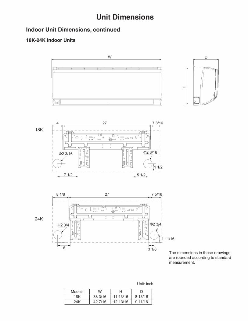
18K-24K Indoor Units
W D
H
24 77 3/16
5 1/27 1/2
1 1/2
Φ2 3/16 Φ2 3/16
3 1/86
1 11/16
8 1/8 27 7 5/16
Φ2 3/4 Φ2 3/4
Unit: inch
18K
24K
Models W H D18K 38 3/16 11 13/16 8 13/1624K 42 7/16 12 13/16 9 11/16
Indoor Unit Dimensions, continued
The dimensions in these drawings are rounded according to standard measurement.

Unit: inch
3513 3/8
27 9
/16
15 5/8 38
14 5
/16
22
18K-24K Outdoor Units
Outdoor Unit Dimensions
The dimensions in these drawings are rounded according to standard measurement.
Unit Dimensions

Air Velocity Patterns for High WallMax Horizontal Distance
Unit: ft. (m)Model Cooling Mode Heating Mode
M4MLW1818A 30.2 (9.2) 21.3 (6.5)
Clearance Requirements
valve cover
Space to the wal l
Space to the ceiling
Space to the wall
Space to the wall
Air outlet side Space to the floor
or moreor more
6 in. or more 6 in. or more
12 in. or more
20 in. or more
20 in
. or m
ore
12 in. o
r more
or m
ore .ni97
or more
Space to the obstruction
Air outlet side
Space to the wall
Air inlet side
The dimensions of the space necessary for correct installation of the appliance including the minimum permissible distances to adjacent structures
6 in.
66in.
118 in.
NOTE: The maximum recommended height from the floor to the bottom of the indoor unit is 11.5 ft. (3.5 m).

Performance Data
Capacities in these performance tables reflect normal operation at the temperatures indicated. See specification tables for certified values under prescribed test conditions.
TC* SHC** TC SHC TC SHC TC SHC0 9000 6800 9500 7200 10500 7900 11600 810010 10700 8300 11300 8800 12300 9600 13300 1020020 12200 9500 13000 10100 14300 11200 15000 1180030 12900 10100 13800 10800 15400 12000 16000 1260040 13500 10500 14400 11300 16100 12400 16800 1310050 14100 11000 15100 11700 17200 13000 16500 1270055 14700 11500 15800 12300 17300 13300 17500 1350060 15500 12100 16600 13000 17700 13800 18400 1440065 16700 13000 17800 13900 18600 14500 19400 1510070 17300 13500 18400 14400 19200 15000 19900 1560075 17200 13400 18300 14300 19000 14800 19800 1550080 12400 13200 18000 14000 18800 14600 19600 1550085 4400 12800 17500 13600 18600 14400 19200 1550090 8400 12400 16600 13000 18100 14100 18700 1500095 15400 12000 15700 12300 17600 13700 18200 14400100 15000 11700 15300 11900 16800 13500 17500 13900105 14500 11300 14900 11600 16100 13200 16900 13400110 14100 11000 14600 11400 15400 12800 16200 12700115 13700 10700 14300 11100 14800 12500 15500 12100
M4TLS1818A1/M4MLW1818A1 ‐ Heating Mode Performance Data
TC* TC TC TC‐13 9800 9700 9200 9100‐10 10400 10100 9800 9700‐5 11000 10600 10400 103000 12000 11500 11300 112005 12500 12000 11800 1170010 13100 12600 12300 1220015 13400 12900 12600 1250020 14000 13500 13200 1310025 15300 14800 14500 1440030 16400 15800 15500 1540035 17400 16900 16600 1640040 18500 17900 17600 1740045 19900 19400 19000 1880050 20800 20200 19800 1960055 21100 20400 20000 1980060 21500 20800 20400 2020065 21900 21200 20800 2060070 22200 21500 21100 2090075 22500 21800 21400 21200
M4TLS1818A1/M4MLW1818A1 ‐ Cooling Mode Performance DataOutdoor
Ambient Air Temperature
(°F)
Indoor Entering Air Temperature (Dry Bulb/Wet Bulb)
Outdoor Ambient Air Temperature
(°F)
Indoor Entering Air Temperature
68/57°F 73/61°F 79/64°F 80/67°F
68°F 73°F 80°F 82°F
*Total Capacity **Sensible Heat Capacity
*Total Capacity

01/18
The manufacturer has a policy of continuous product and product data improvement and it reserves the right
to change design and specifications without notice.
Mechanical Specifications
Mini-Split Indoor High Wall
General
The High Wall mounted type air handler shall be completely factory assembled including coil, condensate drain pan, fan motor, washable filter, air purifying filter and electric controls to be used with a wireless remote controller. Unit shall be shipped with a unit mounting plate. Unit shall be matched with an Ameristar outdoor unit, rated and tested in accordance with AHRI standard. Unit shall be ETL listed.
Unit Casing
Casing shall be provided with knockouts on the right, and left of the unit to facilitate pip-ing and electrical connection on either side of the unit. An electrical service cover shall be provided to permit easy access to the electri-cal terminal strip.
Discharge Airflow and Distribution System
Unit shall have auto swing, dual horizon-tal blades to optimize the aperture outlet for vertical airflow and air distribution. Blade shall close automatically when the air conditioner is turned off to minimize dust entering the unit. Five-Step preset program on the remote controller shall be available to control the blade angle.
Manually adjusted wide-angle louvers shall be provided to adjust the coverage and direction of airflow.
Controls
Units shall have the capability to be con-trolled remotely through wall-mounted wired options (sold separately) as well as a wireless remote option.
Remote Controller
The unit shall have a wireless infrared re-mote controller with easy reading digital display panel to start, stop and regulate the air conditioner from a distance.
The wireless controller is included with all units.
Healthy Filters
The unit shall have an active carbon and catechin filter with the unit.The filters need to be cleaned at least once a year.
Mini-Split Outdoor Unit
General
This unit is fully charged from the factory for up to 25 feet of piping. This unit is designed to operate at outdoor ambient temperatures as high as 115°F. Cooling capacities with the mini-split air handler shown in the catalog are AHRI certified. The unit is ETL listed for out-door application.
Unit Casing
The unit casing is constructed of heavy gauge, galvanized steel and painted with a weather-resistant powder paint.
Refrigerant Controls
The compressor motor and condenser fan motor are controlled and monitored by an integrated electronic module. Additionally, the same module moni-tors sensors to control refrigerant flow through the sealed system as well as air flow.
Compressor
The compressor features internal over temperature and pressure protection; total dipped hermetic motor windings. Other features include: centrifugal oil pump and low vibration and noise.
Condenser Coil
The condensor coil is constructed from aluminum plate fins and copper tubing. The coil provides air flow resistance and efficient heat transfer.
Low Ambient Operation
Matched Ameristar ductless products, have cooling capabilities at outdoor am-bient temperatures as low as 0° F and heating capabilities at outdoor ambient temperatures as low as -13° F.

SUBMITTAL
© 2018 Ingersoll Rand All Rights Reserved
TAG: _________________________________
18 SERIES
Single Zone Mini-SplitInverter System
M4MLW1824A1N0AM4TLS1824A11NA
M4MLW1824A-SUB-1A
Specifications
MODEL - Heat Pump Only
RATED Volts/PHFrequency (Hz)Rated Cooling / Heating Capacity (Btu/h):Minimum Cooling Capacity (@95F) (Btu/h):Maximum Cooling Capacity (@95F) (Btu/h):Minimum Heating Capacity (@47F) (Btu/h):Maximum Heating Capacity (@47F) (Btu/h):Maximum Heating Capacity (@17F) (Btu/h):Total Capacity (W) (High/Standard/Low):Rated Power Input (W)Nominal Input Current (A)SEER / HSPF Air Flow Volume (CFM) (H/M/L)Dehumidifying Volume (pt./h)EER (Btu/W hr)/COP
Indoor UnitFan Motor Speed (r/min) (SH/H/M/L)Fan Motor RLA(A)EvaporatorPipe Diameter (inch)Row Fin Gap (inch)Coil length (L) x depth (D) x coil width (W) (inch)Output of Swing Motor (W)Fuse (A)Sound Power Level dB (A)(SH/H/M/L)Sound PRESSURE Level dB (A)(SH/H/M/L) 1Uncrated Dimension (W/H/D) (inch)Crated Dimension of Package (L/W/H) (inch)Net Weight /Gross Weight (lbs)
Outdoor UnitCompressor TypeCompressor OilL.R.A. (A)Compressor RLA(A)Compressor Power Input(W)Throttling MethodWorking Temp Range (°F)CondenserPipe Diameter (inch)Row Fin Gap (inch)Coil length (l) x depth (D) x coil width (W) (inch)Fan Motor Speed (rpm)Output of Fan Motor (W)Fan Motor RLA (A)Air Flow Volume of Outdoor Unit (CFM)Fan Diameter (inch)Defrosting MethodSound Power Level dB (A)Sound PRESSURE Level dB (A) 1Uncrated Dimension (W/H/D) (inch)Crated Dimension of Package (W/L/H) (inch)Net Weight /Gross Weight (lbs)Refrigerant Charge (oz)MCAMOP
Connection PipeRefrigerant additional charge(oz/ft)Outer Diameter Liquid Pipe (inch)Outer Diameter Gas Pipe (inch)Max Height Distance (ft)Max Length Distance (ft)
1 Sound PRESSURE Level @ 3.3 ft. dB(A)
M4MLW1824A / M4TLS1824ACooling Heating
208 / 230 / 1 60Hz
22800 25000 8600 -24000 -- 8600- 26000- 16000
7034 / 6450 / 2500 7600 / 7034 / 25002010 21308.92 9.4518.4 10.5
1200 / 1050 / 900 / 7504.2
11.0 3.3
M4MLW1824A1N01300 / 1150 / 1000 / 850 1300 / 1150 / 1000 / 850
0.32Aluminum Fin-Copper Tube
0.2862 - 0.059
33.25 x 1.0 x 13.5 2.53.15
63 / 59 / 56 / 5249 / 46 / 42 / 3642.4 x 12.8 x 9.745.2 x 16.3 x 13.8
37.5 / 45.2
M4TLS1824A11NRotary
RB68EB (POE Oil)25.012.181440EEV
0 - 115 -13 - 75Aluminum Fin-Copper Tube
0.281 - 0.055
36.8 x 1.5 x 2680060
0.40320020.5
Automatic Defrosting6858
37.6 x 27.6 x 15.640.5 x 18 x 29.5
103.6 / 113.556.416.025.0
0.541/45/866100

Unit Dimensions
18K-24K Indoor Units
W D
H
24 77 3/16
5 1/27 1/2
1 1/2
Φ2 3/16 Φ2 3/16
3 1/86
1 11/16
8 1/8 27 7 5/16
Φ2 3/4 Φ2 3/4
Unit: inch
18K
24K
Models W H D18K 38 3/16 11 13/16 8 13/1624K 42 7/16 12 13/16 9 11/16
Indoor Unit Dimensions, continued
The dimensions in these drawings are rounded according to standard measurement.

Unit Dimensions
Unit: inch
3513 3/8
27 9
/16
15 5/8 38
14 5
/16
22
18K-24K Outdoor Units
Outdoor Unit Dimensions
The dimensions in these drawings are rounded according to standard measurement.

Air Velocity Patterns for High WallMax Horizontal Distance
Unit: ft. (m)Model Cooling Mode Heating Mode
M4MLW1824A 31.2 (9.5) 23 (7)
Clearance Requirements
valve cover
Space to the wal l
Space to the ceiling
Space to the wall
Space to the wall
Air outlet side Space to the floor
or moreor more
6 in. or more 6 in. or more
12 in. or more
20 in. or more
20 in
. or m
ore
12 in. o
r more
or m
ore .ni97
or more
Space to the obstruction
Air outlet side
Space to the wall
Air inlet side
The dimensions of the space necessary for correct installation of the appliance including the minimum permissible distances to adjacent structures
6 in.
66in.
118 in.
NOTE: The maximum recommended height from the floor to the bottom of the indoor unit is 11.5 ft. (3.5 m).

Performance Data
Capacities in these performance tables reflect normal operation at the temperatures indicated. See specification tables for certi-fied values under prescribed test conditions.
TC* SHC** TC SHC TC SHC TC SHC0 16400 12900 17500 13700 20000 15700 20400 1600010 17400 13700 18500 14500 21000 16400 21700 1700020 18100 14200 19300 15100 22000 17200 22900 1800030 19100 15000 20500 16100 23300 18300 24500 1920040 20400 16000 22000 17200 24600 19300 26300 2060050 20400 16000 21900 17200 24300 19100 26200 2060055 20400 16000 21800 17100 24000 18800 26100 2050060 20400 16000 21800 17100 23800 18600 25900 2030065 20500 16100 21800 17100 23500 18400 25400 1990070 20400 16000 21700 17000 23200 18200 24900 1960075 19900 15600 21200 16600 23000 18000 24600 1930080 19600 15400 20800 16300 22700 17800 24400 1910085 19300 15200 20600 16200 22500 17600 24100 1890090 19100 14900 20400 16000 22200 17400 24000 1880095 18800 14700 20100 15800 22000 17300 24000 18800100 18400 14400 19700 15500 21800 17100 23700 18600105 18100 14200 19400 15200 21700 17000 23400 18300110 17800 14000 19100 15000 21400 16800 23100 18100115 17500 13800 18900 14800 21100 16600 22800 17900
M4TLS1824A1/M4MLW1824A1 ‐ Heating Mode Performance Data
TC* TC TC TC‐13 14100 13900 13600 13300‐10 15000 14700 14500 14100‐5 15900 15600 15300 150000 17400 17100 16800 164005 18200 17900 17600 1720010 19100 18800 18400 1800015 19600 19300 18900 1850020 20300 20000 19600 1920025 21400 21100 20700 2030030 21800 21500 21100 2070035 22100 21800 21500 2110040 22500 22200 21900 2150045 23700 23400 23000 2250050 24400 23900 23500 2290055 24700 24200 23800 2320060 25100 24700 24200 2360065 25700 25200 24700 2410070 26100 25600 25100 2450075 26400 26000 25400 24800
M4TLS1824A1/M4MLW1824A1 ‐ Cooling Mode Performance DataOutdoor
Ambient Air Temperature
(°F)
Indoor Entering Air Temperature (Dry Bulb/Wet Bulb)
Outdoor Ambient Air Temperature
(°F)
Indoor Entering Air Temperature
68/57°F 73/61°F 79/64°F 80/67°F
68°F 73°F 80°F 82°F
*Total Capacity **Sensible Heat Capacity
*Total Capacity
01/18
The manufacturer has a policy of continuous product and product data improvement and it reserves the right
to change design and specifications without notice.
Mechanical Specifications
Mini-Split Indoor High Wall
General
The High Wall mounted type air handler shall be completely factory assembled including coil, condensate drain pan, fan motor, washable filter, air purifying filter and electric controls to be used with a wireless remote controller. Unit shall be shipped with a unit mounting plate. Unit shall be matched with an Ameristar outdoor unit, rated and tested in accordance with AHRI standard. Unit shall be ETL listed.
Unit Casing
Casing shall be provided with knockouts on the right, and left of the unit to facilitate pip-ing and electrical connection on either side of the unit. An electrical service cover shall be provided to permit easy access to the electri-cal terminal strip.
Discharge Airflow and Distribution System
Unit shall have auto swing, dual horizon-tal blades to optimize the aperture outlet for vertical airflow and air distribution. Blade shall close automatically when the air conditioner is turned off to minimize dust entering the unit. Five-Step preset program on the remote controller shall be available to control the blade angle.
Manually adjusted wide-angle louvers shall be provided to adjust the coverage and direction of airflow.
Controls
Units shall have the capability to be con-trolled remotely through wall-mounted wired options (sold separately) as well as a wireless remote option.
Remote Controller
The unit shall have a wireless infrared re-mote controller with easy reading digital display panel to start, stop and regulate the air conditioner from a distance.
The wireless controller is included with all units.
Healthy Filters
The unit shall have an active carbon and catechin filter with the unit.The filters need to be cleaned at least once a year.
Mini-Split Outdoor Unit
General
This unit is fully charged from the factory for up to 25 feet of piping. This unit is designed to operate at outdoor ambient temperatures as high as 115°F. Cooling capacities with the mini-split air handler shown in the catalog are AHRI certified. The unit is ETL listed for out-door application.
Unit Casing
The unit casing is constructed of heavy gauge, galvanized steel and painted with a weather-resistant powder paint.
Refrigerant Controls
The compressor motor and condenser fan motor are controlled and monitored by an integrated electronic module. Additionally, the same module moni-tors sensors to control refrigerant flow through the sealed system as well as air flow.
Compressor
The compressor features internal over temperature and pressure protection; total dipped hermetic motor windings. Other features include: centrifugal oil pump and low vibration and noise.
Condenser Coil
The condensor coil is constructed from aluminum plate fins and copper tubing. The coil provides air flow resistance and efficient heat transfer.
Low Ambient Operation
Matched Ameristar ductless products, have cooling capabilities at outdoor am-bient temperatures as low as 0° F and heating capabilities at outdoor ambient temperatures as low as -13° F.