1 Serial Communications Lecture 11. 2 In these notes... General Communications Serial Communications...
23
1 Serial Communications Serial Communications Lecture 11
-
Upload
brett-potter -
Category
Documents
-
view
227 -
download
3
Transcript of 1 Serial Communications Lecture 11. 2 In these notes... General Communications Serial Communications...
1
Serial CommunicationsSerial Communications
Lecture 11
2
In these notes . . . In these notes . . . • General Communications• Serial Communications
– RS232 standard– UART operation– Polled Code– Interrupt Driven Code
• Read M16C/26 Hardware Manual pp. 108-118, 128-136

3
• There was no standard for networks in the early days and as a result it was difficult for networks to communicate with each other.
• The International Organization for Standardization (ISO) recognized this and in 1984 introduced the Open Systems Interconnection (OSI) reference model.
• The OSI reference model organizes network functions into seven numbered layers.
• Each layer provides a service to the layer above it in the protocol specification and communicates with the same layer’s software or hardware on other computers.
• Layers 5-7 are concerned with services for the applications.
• Layers 1-4 are concerned with the flow of data from end to end through the network
Data CommunicationsData Communications

4
Physical Layer (1) – Serial CommunicationsPhysical Layer (1) – Serial Communications• The basic premise of serial communications is that one
or two wires are used to transmit digital data.– Of course, ground reference is also needed (extra wire)
• Can be one way or two way, usually two way, hence two communications wires.
• Often other wires are used for other aspects of the communications (ground, “clear-to-send”, “data terminal ready”, etc).
Tx
TxRx
RxMachine 1 Machine 2
101101100111
001101101111
5
Serial Communication BasicsSerial Communication Basics
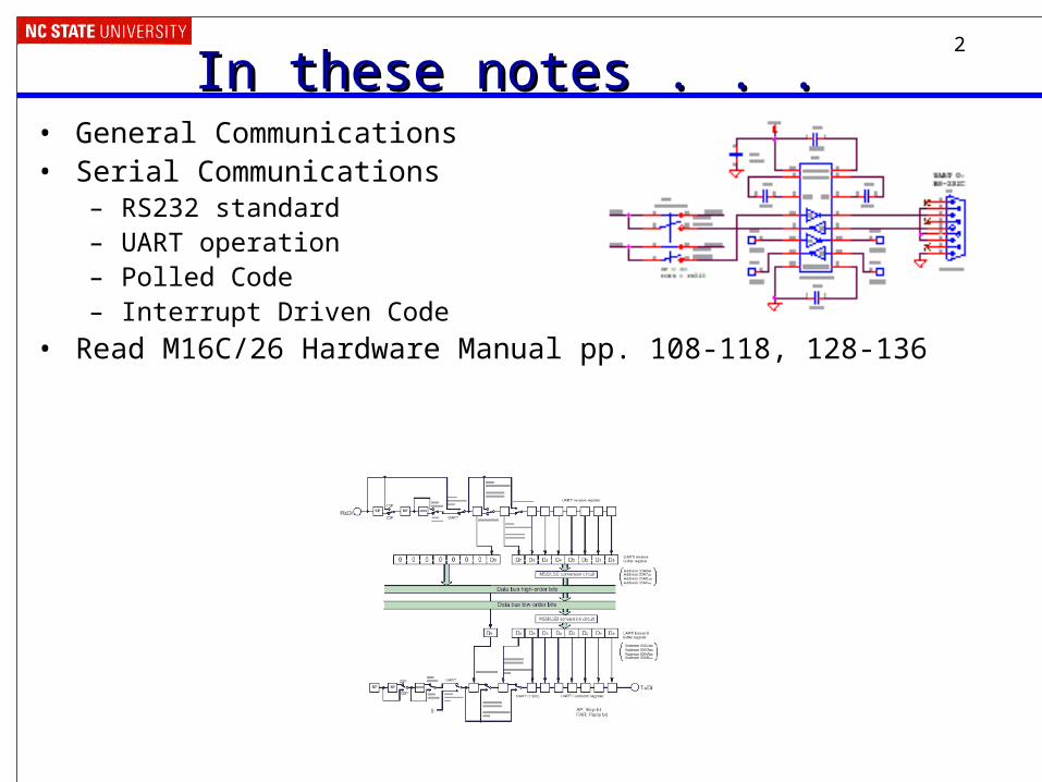
• Send one bit of the message at a time
• Message fields– Start bit (one bit)– Data (LSB first or MSB, and size – 7, 8, 9 bits)– Optional parity bit is used to make total number of ones in data even or odd– Stop bit (one or two bits)
• All devices on network or link must use same communications parameters – The speed of communication must be the same as well (300, 600, 1200, 2400,
9600, 14400, 19200, etc.)• More sophisticated network protocols have more information in each message
– Medium access control – when multiple nodes are on bus, they must arbitrate for permission to transmit
– Addressing information – for which node is this message intended?– Larger data payload– Stronger error detection or error correction information– Request for immediate response (“in-frame”)
Message
Databits

6
Bit Rate vs. Baud RateBit Rate vs. Baud Rate• Bit Rate: how many data bits are transmitted per second?• Baud Rate: how many symbols are transmitted per
second? – == How many times does the communication channel change
state per second?
– A symbol may be represented by a voltage level, a sine wave’s frequency or phase, etc.
• These may be different– Extra symbols (channel changes) may be inserted for framing,
error detection, acknowledgment, etc. These reduce the bit rate
– A single symbol might encode more than one bit. This increases the bit rate.
• E.g. multilevel signaling, quadrature amplitude modulation, phase amplitude modulation, etc.

7
Serial Communication BasicsSerial Communication Basics• RS232: rules on connector, signals/pins, voltage levels, handshaking, etc.• RS232: Fulfilling All Your Communication Needs, Robert Ashby• Quick Reference for RS485, RS422, RS232 and RS423• Not so quick reference:
The RS232 Standard: A Tutorial with Signal Names and Definitions, Christopher E. Strangio
• Bit vs Baud rates: http://www.totse.com/en/technology/telecommunications/bits.html

8
UART ConceptsUART Concepts• UART
– Universal – configurable to fit protocol requirements
– Asynchronous – no clock line needed to deserialize bits
– Receiver/Transmitter
• M30262 has three– UART0, 1, and 2
– UART1 talks to USBMon board, enables us to do in-circuit debugging
– Can operate in asynchronous or synchronous (not used here) modes
– See MCU Hardware Manual for details, or else the remaining slides might be confusing

9
RS232 Communications CircuitRS232 Communications Circuit• Example RS-232 buffer (level-shifting) circuit
– Not included on SKP16C26Max202/3232 includescharge pump to generate+10 V and -10V from single 5V supply
Logic-level signals(Vcc or Ground)
RS232-level signals(> 3 V or < -3 V)

10
UART ConceptsUART Concepts
UART subsystems–Two fancy shift registers
• Parallel to serial for transmit
• Serial to parallel for receive
–Programmable clock source
• Clock must run at 16x desired bit rate
–Error detection• Detect bad stop or parity
bits• Detect receive buffer
overwrite–Interrupt generators
• Character received• Character transmitted,
ready to send another

11
Setting up the Serial PortSetting up the Serial Port• We will use UART 0, so all of the references to a
UART will have “u0” in them.• There are several “control” registers you need to set up
before you can communicate.– First, you need to set up the speed of your port.
– Select 8 data bits, no parity, one stop bit (8N1)
– Enable transmitter and receiver
• Code examples:– serial26.c/serial26.h in the SKPTest application
– serial_poll_demo.c/serial_poll_includes on notes page

12
Setting up Speed of the Serial PortSetting up Speed of the Serial Port• Baud rate = 19,200 baud
– 20 MHz/(16*19,200 baud) = 65.1
– Load u0brg with 65-1 = 64
– Actual baud rate = 20 MHz/(16*65) = 19230.8 baud = 0.16% error
– If error is too large, communication fails
– This uses count source f1. You can also select f8 (1/8 clock) and f32 (1/32 of clock). Adjust BRG accordingly.
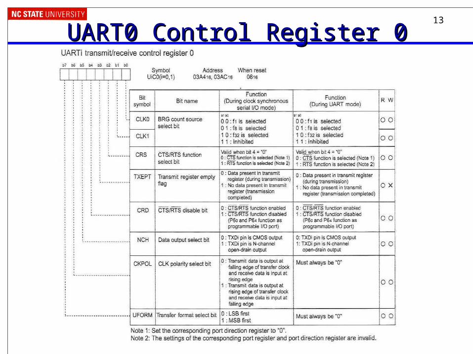
13
UART0 Control Register 0UART0 Control Register 0

14
UART0 Control Register 1UART0 Control Register 1

15
UART Control Register 2UART Control Register 2

16
UART0 Tx/Rx Mode RegisterUART0 Tx/Rx Mode Register

17
Configuring UART0Configuring UART0void init_UART0() { // UART 0 bit rate generator u0brg =64;
// UART 0 transmit/receive mode register smd2_u0mr = 1; // eight data bits smd1_u0mr = 0; smd0_u0mr = 1; ckdir_u0mr = 0; // internal clock stps_u0mr = 0; pry_u0mr = 0; prye_u0mr = 0; // no parity
// uart0 t/r control register 0 // 20 MHz -> 19,200 baud clk1_u0c0 = 0; // select f/1 clock clk0_u0c0 = 0; nch_u0c0 = 0; // CMOS push-pull output ckpol_u0c0 = 0; // required uform_u0c0 = 0; // required crs_u0c0 = 0; // required crd_u0c0 = 1; // required
// uart0 t/r control register 1 te_u0c1 = 1; // enable transmitter re_u0c1 = 1; // enable receiver
// uart t/r control register 2 u0irs = 0; // select interrupt source u1rrm = 0; // select interrupt source clkmd0 = 0; // n/a clkmd1 = 0; // n/a rcsp=1; // rxdo port to p6_2 }

18
Using the UARTUsing the UART• When can we transmit?
– Transmit buffer must be empty
– Can poll ti_u0c1 (UART0, control register 1, transmit buffer empty, 0x03A5, bit 1)
– Or we can use an interrupt, in which case we will need to queue up data
• Put data to be sent into u0tbl (UART0, transmitter buffer, low byte, 0x03A2)
• Notice the differences between ones (1) and ells (l)
• When can we receive a byte?– Receive buffer must be full
– Can poll ri_u0c1 (UART0, control register 1, receive complete flag, 0x03A5, bit 3)
– Or we can use an interrupt, and again we will need to queue the data
• Get data from u0rbl (UART0, receive buffer, low byte, 0x03A6)

19
Transmit BufferTransmit Buffer
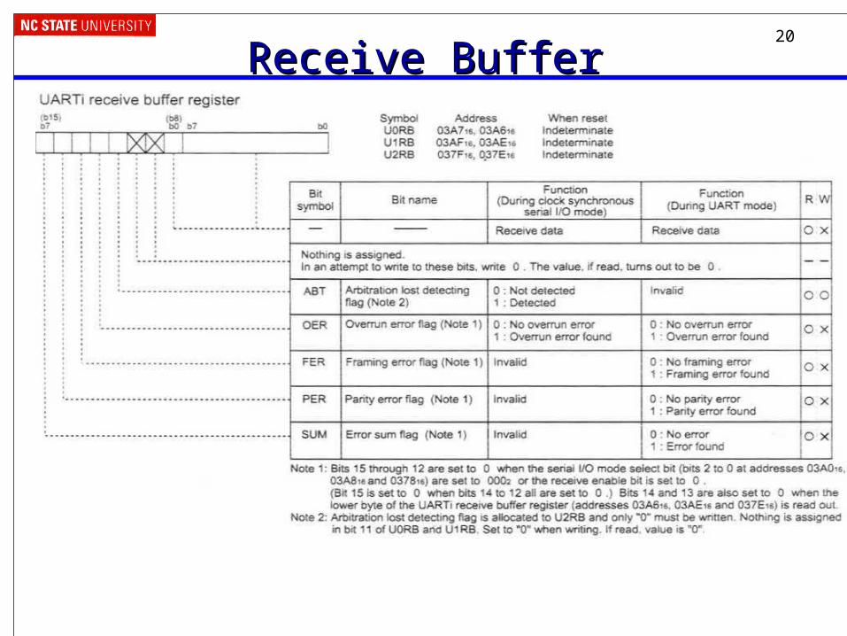
20
Receive BufferReceive Buffer

21
Example 1: Send Out Many CharactersExample 1: Send Out Many Characters• Send out every character and
symbol from ‘A’ to ‘z’ and then repeat
• Use polling to determine when transmit buffer is empty and can be reloaded
void demo1() { // polled transmit demo unsigned long ctr; char c='A'; while (SW4) { while (!ti_u0c1); // wait for
// transmit buffer empty
for (ctr=0; ctr<50000; ctr++);// delay so the letters// come out slowly
u0tbl = c; // load c into // transmit buffer
c++; // ! if (c>'z') c = 'A'; // wrap around }}

22
Example 2: Make the Code More ElegantExample 2: Make the Code More Elegant• Create a function to transmit a
null-terminated string
void demo2_ser_tx(far char * buf) {
// polled buffer transmit demo // transmit a null-terminated // string while (*buf) { while (!ti_u0c1); // wait for
// transmitter empty u0tbl = *buf; // load
// character into buffer
buf++; // increment buffer // pointer
}} void demo2() { while (SW4) { demo2_ser_tx("Testing!\n\r"); delay(100000); }}

23
Example 3: Echo Received DataExample 3: Echo Received Data• Wait for character to be
received (via polling)
• Add one to character if switch 2 is pressed (LSSC (laughably simple substitution cipher))
• Wait for transmitter to be empty (ready)
• Send character
• If the character is a “return” send a line feed to make terminal scroll to new line
void demo3() { // polling echo example char c; while (SW4) { while (!ri_u0c1) // await rx ; c = u0rbl; // get character if (!SW2) // "Encrypt“ c c += 1; while (!ti_u0c1) // await tx ; u0tbl = c; // send character // cr/lf translation for terminal if (c == '\r') { while (!ti_u0c1)
; u0tbl = '\n'; } }}