1 SAFETY PRECAUTIONS 2 GENERAL DESCRIPTION · Please indicate the arti-cle and serial number...
5
IMPORTANT: BEFORE STARTING THE EQUIPMENT, READ THE CONTENTS OF THIS MANUAL, WHICH MUST BE STORED IN A PLACE FAMILIAR TO ALL USERS FOR THE ENTIRE OPERATIVE LIFE-SPAN OF THE MACHINE. THIS EQUIPMENT MUST BE USED SOLELY FOR WEL- DING OPERATIONS. 1 SAFETY PRECAUTIONS WELDING AND ARC CUTTING CAN BE HARMFUL TO YOURSELF AND OTHERS.The user must therefore be edu- cated against the hazards, summarized below, deriving from welding operations. For more detailed information, order the manual code 3.300.758 ELECTRIC SHOCK - May be fatal. · Install and earth the welding machine according to the applicable regulations. · Do not touch live electrical parts or electrodes with bare skin, gloves or wet clothing. · Isolate yourselves from both the earth and the workpiece. · Make sure your working position is safe. FUMES AND GASES - May be hazardous to your health. · Keep your head away from fumes. · Work in the presence of adequate ventilation, and use ventilators around the arc to prevent gases from forming in the work area. ARC RAYS - May injure the eyes and burn the skin. · Protect your eyes with welding masks fitted with fil- tered lenses, and protect your body with appropriate safety garments. · Protect others by installing adequate shields or curtains. RISK OF FIRE AND BURNS · Sparks (sprays) may cause fires and burn the skin; you should therefore make sure there are no flam- mable materials in the area, and wear appropriate protective garments. NOISE This machine does not directly produce noise excee- ding 80dB. The plasma cutting/welding procedure may produce noise levels beyond said limit; users must therefore implement all precautions required by law. PACEMAKERS · The magnetic fields created by high currents may affect the operation of pacemakers. Wearers of vital electronic equip- ment (pacemakers) should consult their physician before beginning any arc welding, cutting, gouging or spot welding operations. EXPLOSIONS · Do not weld in the vicinity of containers under pres- sure, or in the presence of explosive dust, gases or fumes. · All cylinders and pressure regulators used in welding operations should be handled with care. ELECTROMAGNETIC COMPATIBILITY This machine is manufactured in compliance with the instruc- tions contained in the harmonized standard EN50199, and must be used solely for professional purposes in an industrial environment. There may be potential difficul- ties in ensuring electromagnetic compatibility in non- industrial environments. IN CASE OF MALFUNCTIONS, REQUEST ASSISTANCE FROM QUALIFIED PERSONNEL. 2 GENERAL DESCRIPTION 2.1 SPECIFICATIONS This manual has been prepared for the purpose of educa- ting personnel assigned to install, operate and service the welding machine. This equipment is a constant-voltage power source, suita- ble for MIG/MAG and OPEN-ARC welding. Upon receiving the machine, make sure there are no broken or damaged parts. The purchaser should address any complaints for los- ses or damage to the vector. Please indicate the arti- cle and serial number whenever requesting informa- tion about the welding machine. 2.2 EXPLANATION OF TECHNICAL SPECIFICATIONS EN 50199 The welding machine is manufactured EN60974.1 according to these international stan- dards. N° serial number, which must always be indi- cated on any type of request regarding the welding machine. three-phase transformer-rectifier. Flat characteristic. MIG/MAG. Suitable for continuous electrode welding. AMP Unconventional welding current. The values represent the minimum and maximum levels attainable in welding. U0. Secondary open-circuit voltage (peak V) X. Duty cycle percentage. The duty cycle expresses the percentage of 10 minutes during which the welding machine may run at a certain current without overheating. I2. Welding current U2. Secondary voltage with welding current I2. U1. Rated supply voltage 3~ 50/60Hz 50- or 60-Hz three-phase power supply. I1. Absorbed current at the corresponding welding current I2. IP21 Protection rating for the housing. Grade 1 as the second digit means that this equipment is suitable for use out- doors in the rain. Suitable for use in high-risk environ- ments. NOTES: The welding machine has also been designed for use in environments with a pollution rating of 3. (See IEC 664). S INSTRUCTION MANUAL FOR WIRE WELDING MACHINE
Transcript of 1 SAFETY PRECAUTIONS 2 GENERAL DESCRIPTION · Please indicate the arti-cle and serial number...

IMPORTANT: BEFORE STARTING THE EQUIPMENT,READ THE CONTENTS OF THIS MANUAL, WHICH MUSTBE STORED IN A PLACE FAMILIAR TO ALL USERS FORTHE ENTIRE OPERATIVE LIFE-SPAN OF THE MACHINE.THIS EQUIPMENT MUST BE USED SOLELY FOR WEL-DING OPERATIONS.
1 SAFETY PRECAUTIONS
WELDING AND ARC CUTTING CAN BE HARMFUL TOYOURSELF AND OTHERS.The user must therefore be edu-cated against the hazards, summarized below, deriving fromwelding operations. For more detailed information, order themanual code 3.300.758
ELECTRIC SHOCK - May be fatal.· Install and earth the welding machine according tothe applicable regulations.· Do not touch live electrical parts or electrodes with
bare skin, gloves or wet clothing.· Isolate yourselves from both the earth and the workpiece.· Make sure your working position is safe.
FUMES AND GASES - May be hazardous to your health.· Keep your head away from fumes.· Work in the presence of adequate ventilation, anduse ventilators around the arc to prevent gases from
forming in the work area.
ARC RAYS - May injure the eyes and burn the skin.· Protect your eyes with welding masks fitted with fil-tered lenses, and protect your body with appropriatesafety garments.
· Protect others by installing adequate shields or curtains.
RISK OF FIRE AND BURNS· Sparks (sprays) may cause fires and burn the skin;you should therefore make sure there are no flam-mable materials in the area, and wear appropriate
protective garments.
NOISEThis machine does not directly produce noise excee-ding 80dB. The plasma cutting/welding proceduremay produce noise levels beyond said limit; users
must therefore implement all precautions required by law.
PACEMAKERS· The magnetic fields created by high currents may affect theoperation of pacemakers. Wearers of vital electronic equip-ment (pacemakers) should consult their physician beforebeginning any arc welding, cutting, gouging or spot weldingoperations.
EXPLOSIONS· Do not weld in the vicinity of containers under pres-sure, or in the presence of explosive dust, gases orfumes. · All cylinders and pressure regulators used in
welding operations should be handled with care.ELECTROMAGNETIC COMPATIBILITYThis machine is manufactured in compliance with the instruc-tions contained in the harmonized standard EN50199, and
must be used solely for professional purposes in anindustrial environment. There may be potential difficul-ties in ensuring electromagnetic compatibility in non-industrial environments.IN CASE OF MALFUNCTIONS, REQUEST ASSISTANCEFROM QUALIFIED PERSONNEL.
2 GENERAL DESCRIPTION
2.1 SPECIFICATIONSThis manual has been prepared for the purpose of educa-ting personnel assigned to install, operate and service thewelding machine.This equipment is a constant-voltage power source, suita-ble for MIG/MAG and OPEN-ARC welding.Upon receiving the machine, make sure there are nobroken or damaged parts.The purchaser should address any complaints for los-ses or damage to the vector. Please indicate the arti-cle and serial number whenever requesting informa-tion about the welding machine.
2.2 EXPLANATION OF TECHNICAL SPECIFICATIONS
EN 50199 The welding machine is manufactured EN60974.1 according to these international stan-
dards.N° serial number, which must always be indi-
cated on any type of request regarding the welding machine.
three-phase transformer-rectifier.
Flat characteristic.MIG/MAG. Suitable for continuous electrode welding.AMP Unconventional welding current.
The values represent the minimum and maximum levels attainable in welding.
U0. Secondary open-circuit voltage (peak V)X. Duty cycle percentage.
The duty cycle expresses the percentageof 10 minutes during which the welding machine may run at a certain current without overheating.
I2. Welding currentU2. Secondary voltage with welding current
I2.U1. Rated supply voltage3~ 50/60Hz 50- or 60-Hz three-phase power supply.I1. Absorbed current at the corresponding
welding current I2.IP21 Protection rating for the housing.
Grade 1 as the second digit means that this equipment is suitable for use out-doors in the rain.Suitable for use in high-risk environ-ments.
NOTES: The welding machine has also been designed foruse in environments with a pollution rating of 3. (See IEC664).
S
INSTRUCTION MANUAL FOR WIRE WELDING MACHINE

3 INSTALLATION
• Only skilled personnel should install the machine .• All connections must be carried out according to currentregulations, and in full observance of safety laws.
3.1 PLACEMENT
Dust, dirt, and any other foreign matter entering the wel-ding machine can interfere with ventilation and thus withsmooth operation.Mount the handle, the 2 cylinder supports and pivot sup-port.Mount the 2 fixed wheels on the wheel support located ontop of the welder. remove the Styrofoam buffer from underthe bottom, at the back of the welding machine. Insert thewheel support on the bottom, fastening it in place wiyh thescrews provided.
3.2 INTERNAL CONNECTIONS
• Before working inside the welding machine, make surethat the plug is disconnected from the power mains.• After final inspection, the welding machine is con-nected to the voltage indicated on the power supplycable.• To change the supply voltage, remove the right sidepanel and arrange the voltage change terminal boardconnections as shown in the figure.• Do not use the welding machine without its cover or sidepanels for obvious safety reasons, and to avoid alteringthe cooling conditions for internal components.• Connect a plug suitable for the absorbed current to thepower supply cable.
• Connect the yellow-green wire of the machine mains toan efficient grounding socket.
3.3 EXTERNAL CONNECTIONS
3.3.1 Connecting the mass clip.• Connect the terminal of the ground cable to one of theimpedance sockets of the machine, keeping in mind thatthe "maximum impedance" socket will give firmlyembedded welds, and is recommended for welding alumi-num, stainless steel and carbon steel with binary or ter-nary blends.The "minimum impedance" socket is suitable for wel-ding carbon steels, with carbon dioxide gaseous protec-tion, and in upright positions with binary or ternary blends.The minimum impedance socket also ensures promptstarts under any conditions.• After deciding on the appropriate impedance output,connect the mass clip to the workpiece.
3.3.2 Connecting the gas hose.• The gas cylinder must be equipped with a pressure regu-lator and flow gauge.• Connect the gas hose leaving the rear of the machine,only after positioning the cylinder.• Adjust the flow gauge to 8-10 liters/minute.
3.3.3 Wire feeder connectionThis power source is compatible with the wire feedersTCA2 and TCA4. To connect the power source to the wirefeeder units use the extension art. 1186 (5 mt) or 1186.20(10 mt).Performances and operating features of the wire feederare described in the operating manuals supplied with thewire feeder itself.
4 DESCRIPTION OF CONTROLS
4.1 CONTROLS ON THE FRONT PANEL OF THE MACHINE
A - Selector switchTurns the machine on and off, and serves to adjust thewelding voltage range.B - Selector switch
fig. 1
fig. 2
9
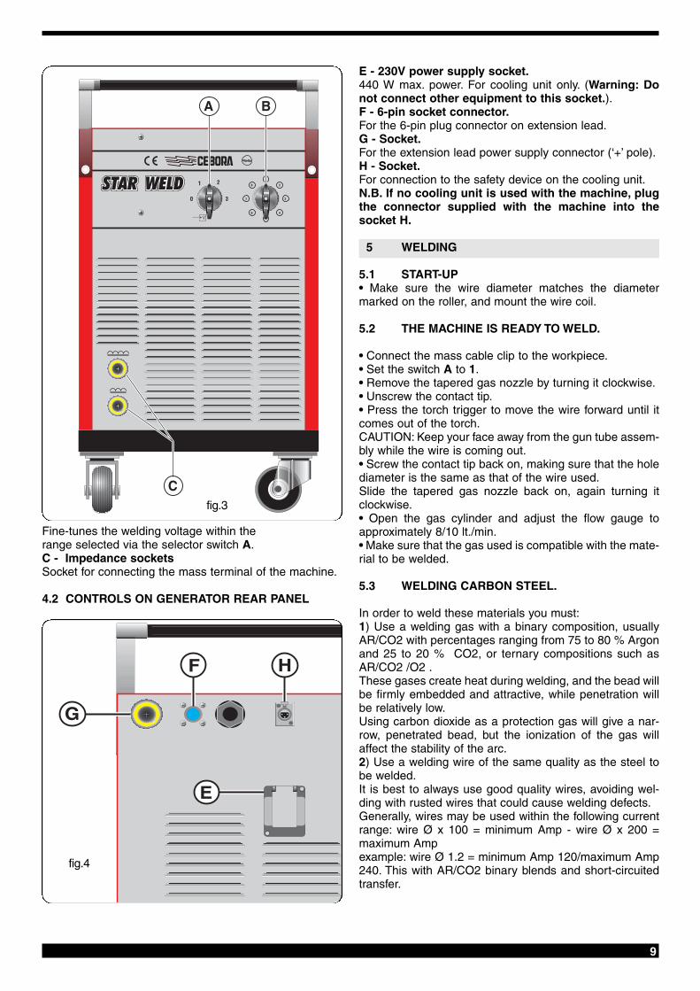
Fine-tunes the welding voltage within the range selected via the selector switch A.C - Impedance socketsSocket for connecting the mass terminal of the machine.
4.2 CONTROLS ON GENERATOR REAR PANEL
E - 230V power supply socket.440 W max. power. For cooling unit only. (Warning: Donot connect other equipment to this socket.).F - 6-pin socket connector.For the 6-pin plug connector on extension lead.G - Socket.For the extension lead power supply connector (‘+’ pole).H - Socket.For connection to the safety device on the cooling unit.N.B. If no cooling unit is used with the machine, plugthe connector supplied with the machine into thesocket H.
5 WELDING
5.1 START-UP• Make sure the wire diameter matches the diametermarked on the roller, and mount the wire coil.
5.2 THE MACHINE IS READY TO WELD.
• Connect the mass cable clip to the workpiece.• Set the switch A to 1.• Remove the tapered gas nozzle by turning it clockwise.• Unscrew the contact tip.• Press the torch trigger to move the wire forward until itcomes out of the torch.CAUTION: Keep your face away from the gun tube assem-bly while the wire is coming out.• Screw the contact tip back on, making sure that the holediameter is the same as that of the wire used.Slide the tapered gas nozzle back on, again turning itclockwise.• Open the gas cylinder and adjust the flow gauge toapproximately 8/10 lt./min.• Make sure that the gas used is compatible with the mate-rial to be welded.
5.3 WELDING CARBON STEEL.
In order to weld these materials you must:1) Use a welding gas with a binary composition, usuallyAR/CO2 with percentages ranging from 75 to 80 % Argonand 25 to 20 % CO2, or ternary compositions such asAR/CO2 /O2 .These gases create heat during welding, and the bead willbe firmly embedded and attractive, while penetration willbe relatively low.Using carbon dioxide as a protection gas will give a nar-row, penetrated bead, but the ionization of the gas willaffect the stability of the arc.2) Use a welding wire of the same quality as the steel tobe welded.It is best to always use good quality wires, avoiding wel-ding with rusted wires that could cause welding defects.Generally, wires may be used within the following currentrange: wire Ø x 100 = minimum Amp - wire Ø x 200 =maximum Ampexample: wire Ø 1.2 = minimum Amp 120/maximum Amp240. This with AR/CO2 binary blends and short-circuitedtransfer.
fig.4
fig.3

3) Avoid welding rusted parts, or those with oil or greasestains.4) Use torches appropriate for the current being used.5) Periodically check that the flaps of the mass clip havenot been damaged, and that the welding cables (torch andmass) do not have any cuts or burns that would create asafety hazard.
5.4 WELDING STAINLESS STEEL
Series 300 stainless steels must be welded using a pro-tection gas with a high Argon content, containing a smallpercentage of O2 to stabilize the arc. The most widelyused blend is AR/O2 98/2.Do not touch the wire with your hands.The welding materials must be better quality than thebase material, and the welding area must be clean.
5.5 WELDING ALUMINUM
In order to weld aluminum you must use:1) 100% Argon as the protection gas.2) A welding wire with a composition suitable for the basematerial to be welded.To weld ALUMAN and ANTICORODAL, use wire with aSilicon content of 3 to 5%.To weld PERALUMAN and ERGAL, use wire containing5% Magnesium.3) A torch prepared for welding aluminum.NOTE: If you only have a torch for steel wires, modify it asfollows:- Make sure that the cable is not longer than 3 meters (itis not recommended that you use longer torches).-Remove the brass liner nut, the gas nozzle, and the con-tact tip, then remove the liner.- Insert the Teflon liner for aluminum, making sure that itprotrudes from both ends.- Screw the contact tip back on so that the liner adherestightly.- In the free end of the liner, insert the liner nipples and theOR gasket, and fasten in place with the nut; do not fastentoo tightly.- Slide the brass tube onto the liner, and insert the entireassembly into the adapter (after first removing the irontube inside the adapter).- Cut the liner diagonally so that it is as close as possibleto the wire feeder roller.The rollers must not be fully tightened.5) Use contact tips suitable for aluminum, with the holecorresponding to the wire diameter to be used for welding.6) Use mills and brushing machines specifically designedfor aluminum, and never use them on other materials.REMEMBER that clean equals quality The wire coils must be stored in nylon bags containing adehumidifying agent.
6 WELDING DEFECTS
1- DEFECT- Porosity (within or outside the bead) CAUSES •Electrode defective (rusted surface)
• Missing safety gas due to:- low gas flow- flow gauge defective- regulator frosted due to no preheating ofthe CO2 protection gas- defective solenoid valve- contact tip clogged with sprays- gas outlet holes clogged- air drafts in welding area.
2- DEFECT- Shrinkage cracks CAUSES • Wire or workpiece dirty or rusted.
• Bead too small.• Bead too concave.• Bead too deeply penetrated.
3- DEFECT- Side cutsCAUSES • Welding pass done too quickly
• Low current and high arc voltages.4- DEFECT- Excessive spraying
CAUSES • Voltage too high.• Insufficient inductance.• No preheating of the CO2 protection gas
7 MAINTAINING THE SYSTEM
Safety gas nozzle . This nozzle must be periodically clea-ned to remove sprayed metal. Replace if distorted orsquashed.Contact tip. Only a good contact between this contact tipand the wire can ensure a stable arc and optimum currentoutput; you must therefore observe the following precau-tions:A) The contact tip hole must be kept free of grime and oxi-dation (rust).B) Sprayed metal sticks more easily after long weldingsessions, blocking the wire flow. The tip must therefore becleaned more often, and replaced if necessary.C) The contact tip must always be firmly screwed onto thetorch body. The thermal cycles to which the torch issubjected can cause it to loosen, thus heating the torchbody and tip and causing the wire to advance unevenly.Wire liner. This is an important part that must be checkedoften, because the wire may deposit copper dust or tinyshavings. Clean it periodically along with the gas lines,using dry compressed air.The liners are subjected to constant wear and tear, andtherefore must be replaced after a certain amount of time.Gearmotor group. Periodically clean the set of feeder rol-lers, to remove any rust or metal residue left by the coils.You must periodically check the entire wire feeder group:hasp, wire guide rollers, liner and contact tip.

11
8 ERRORS DURING USE
NOTE: All tasks should be carried out only by skilledpersonnel.Disconnect the power supply cable from the mains beforeworking on the cables or opening the machine.The machine is equipped with a safety thermostat thattrips in case of overload.You must wait a few minutes afterthis intervention to allow the source to cool.The table below lists the most common errors, causes andsolutions.
MALFUNCTIONPROBABLE CAUSE SOLUTION
Limitedcurrentdelivery
Weldingmetalsplatterswhile wel-ding
The wiredoes notadvance,or advancejerkily
The wirejams andtwistsaround therollers andtorch wireintakeguide
Phase missing
Line fuse burntIncorrect connection on the vol-tage change terminal board
Rectifier diode(s) burntLoose ekectrical torch power ormass connectionsUnever contact in the voltageregulator selector switchTransformer wire broken on theselector switch
Welding parameters incorrectlyset
Insufficient grouding connec-tionsWire moves forward irregularlyWire feeder roller groove toowideLiner jammed or cloggedWire press roller is not tightCoil support clutch too tight
Contact tip cloggedIncorrect contact tip diameterRoller groove incorrectly ali-gnedLiner jammed or clogged
Check the three phases of theline and/or the remote switchcontactsReplace the fuseCheck the terminal board con-nections following the plate dia-gramReplace the rectifierTighten all connections
Change the selector switch
Unscrew the selector switchcontact and peel the wire, beingcareful to remove only the insu-lation; then return it under thecontact.Use the welding voltage andwire speed potentiometers toadjustCheck their efficiency
Incorrect liner diameterReplace the roller
Remove and cleanTightenLoosen the clutch by adjustingthe setting screwReplaceReplaceAlign
Remove and clean
9 REPAIRING THE WELDING MACHINES
Experience has shown that many fatal accidents are cau-sed by poor repairs. That is why it is just as important tofully check a repaired welding machine as a new one.This also protects manufacturers from being held liable fordefects for which others are to blame.
9.1 Rules to follow for repairs• After rewinding the transformer or inductances, the wel-ding machine must pass the applied voltage tests descri-bed in table 2 of paragraph 6.1.3 of the standard EN60974.1 (CEI 26.13). Compliance must be verified as spe-cified in 6.1.3.• If no rewinding has been carried out, a welding machinethat has been cleaned and/or refurbished must pass anapplied voltage test with test voltage values at 50% ofthose given in table 2 of 6.1.3. Compliance must be veri-fied as specified in 6.1.3.• After rewinding and/or replacing parts, the open-circuitvoltage must not exceed the values listed in 10.1 of EN60974.1.• If the repairs are not performed by the manufacturer,repaired welding machine in which any components havebeen replaced or altered must be marked in such a way asto identify who carried out the repairs.• After making a repair, make sure to rearrange the wiringso that there is secure insulation between the primary andsecondary sides of the machine. Do not allow wires tocome into contact with moving parts or those that heat upduring operation. Reassemble all of the clamps as theywere on the original machine, to prevent an accidentalconnection between the primary and secondary circuits ifa conductor should break or disconnect.