1-s2.0-S0013794403000237-main
18
CDM based modelling of damage and fracture mechanisms in concrete under tension and compression q Halina Kuna-Ciskał * , Jacek J. Skrzypek Institute of Mechanics and Machine Design, Cracow University of Technology, 31-864 Krak ow, Poland Received 30 October 2002; accepted 4 November 2002 Abstract Anisotropic damage evolution and crack propagation in the elastic–brittle materials is analysed by the concepts of continuum damage mechanics (CDM) and finite element method (FEM). The modified Murakami–Kamiya (MMK) model of elastic-damage material is used to describe damage anisotropy in concrete. The Helmholtz free energy rep- resentation is discussed. The unilateral crack opening/closure effect is incorporated in such a way that the continuity requirement during unloading holds. The incremental form of the stress–strain equations is developed. The general failure criterion is proposed by checking the positive definiteness of the Hessian matrix of the free energy function. The local approach to fracture (LAF) by FEM is applied to the pre-critical damage evolution that precedes the crack initiation, and the post-critical damage/fracture interaction. Crack is modelled as the assembly of failed finite elements in the mesh, the stiffness of which is reduced to zero when the critical points at stress–strain curves are reached. A concrete specimen with the pre-load, inclined crack is analysed in order to simulate different fracture mechanisms in tension or compression. The constitutive model is capable of predicting the kinked-type crack under tension and the wing-type crack under compression. Ó 2003 Published by Elsevier Ltd. Keywords: Anisotropic damage; Local approach to fracture; Unilateral response; Crack modelling 1. Introduction The increasing demands for a high strength concrete require the adequate constitutive and damage growth modelling, as well as the appropriate predictions of the overall failure mechanisms under monotonic or cyclic loads. Concrete belongs to engineering materials commonly classified as brittle (polycrystalline rocks, concrete, ceramics, and cast iron). The microstructure of concrete exhibits a large number of pre- load micro-cracks, voids, inclusions and other non-homogeneities. The nucleation, growth and interaction of these micro-defects under external loads result in a deterioration process of the material on the micro- scale and, as a consequence, change of the constitutive properties of the material. This micro-scale damage q This paper is the extended version of [29]. * Corresponding author. E-mail address: [email protected] (H. Kuna-Ciskał). 0013-7944/$ - see front matter Ó 2003 Published by Elsevier Ltd. doi:10.1016/S0013-7944(03)00023-7 Engineering Fracture Mechanics 71 (2004) 681–698 www.elsevier.com/locate/engfracmech
-
Upload
georgeedward -
Category
Documents
-
view
217 -
download
1
description
cdm modellinf and fracture mechanics
Transcript of 1-s2.0-S0013794403000237-main

Engineering Fracture Mechanics 71 (2004) 681–698
www.elsevier.com/locate/engfracmech
CDM based modelling of damage and fracture mechanismsin concrete under tension and compression q
Halina Kuna-Ciskał *, Jacek J. Skrzypek
Institute of Mechanics and Machine Design, Cracow University of Technology, 31-864 Krak�oow, Poland
Received 30 October 2002; accepted 4 November 2002
Abstract
Anisotropic damage evolution and crack propagation in the elastic–brittle materials is analysed by the concepts of
continuum damage mechanics (CDM) and finite element method (FEM). The modified Murakami–Kamiya (MMK)
model of elastic-damage material is used to describe damage anisotropy in concrete. The Helmholtz free energy rep-
resentation is discussed. The unilateral crack opening/closure effect is incorporated in such a way that the continuity
requirement during unloading holds. The incremental form of the stress–strain equations is developed. The general
failure criterion is proposed by checking the positive definiteness of the Hessian matrix of the free energy function. The
local approach to fracture (LAF) by FEM is applied to the pre-critical damage evolution that precedes the crack
initiation, and the post-critical damage/fracture interaction. Crack is modelled as the assembly of failed finite elements
in the mesh, the stiffness of which is reduced to zero when the critical points at stress–strain curves are reached. A
concrete specimen with the pre-load, inclined crack is analysed in order to simulate different fracture mechanisms in
tension or compression. The constitutive model is capable of predicting the kinked-type crack under tension and the
wing-type crack under compression.
� 2003 Published by Elsevier Ltd.
Keywords: Anisotropic damage; Local approach to fracture; Unilateral response; Crack modelling
1. Introduction
The increasing demands for a high strength concrete require the adequate constitutive and damage
growth modelling, as well as the appropriate predictions of the overall failure mechanisms under monotonic
or cyclic loads. Concrete belongs to engineering materials commonly classified as brittle (polycrystalline
rocks, concrete, ceramics, and cast iron). The microstructure of concrete exhibits a large number of pre-load micro-cracks, voids, inclusions and other non-homogeneities. The nucleation, growth and interaction
of these micro-defects under external loads result in a deterioration process of the material on the micro-
scale and, as a consequence, change of the constitutive properties of the material. This micro-scale damage
qThis paper is the extended version of [29].* Corresponding author.
E-mail address: [email protected] (H. Kuna-Ciskał).
0013-7944/$ - see front matter � 2003 Published by Elsevier Ltd.
doi:10.1016/S0013-7944(03)00023-7

682 H. Kuna-Ciskał, J.J. Skrzypek / Engineering Fracture Mechanics 71 (2004) 681–698
response causes a fracture process, which yields a structural failure of the element and loss of its carrying
capacity. Deformation process in the damaged material is characterised by a non-linear stress–strain curve
that precedes the local failure. Proper formulation of the local failure criterion is one of the goals of the
present study. The experimental evidence reveals that in brittle-damaged materials the stress–strain non-linearity is mainly caused by a degradation of the elastic properties induced by a progressive deterioration
of the material with increasing loads. The strain softening effect on the energy dissipation due to inelastic
(visco-plastic) deformation may usually be considered as insignificant.
In general, the models used to describe a non-linear damage response of concrete and other brittle
materials have to be capable of capturing essential features of this class of materials. These are: a degra-
dation of the elastic properties and the strain softening due to the development of micro-defects, an ac-
quired anisotropy of the material even though in a virgin state it is considered as initially isotropic, and the
unilateral damage response of concrete in tension or compression. When subjected to the predominant axialcompression a concrete specimen fails by the axial splitting. In contrast, when subjected to the axial tension
it splits perpendicularly to the axial direction. Hence, ultimate failure mechanisms predicted by these
theories must also exhibit essential difference in an overall structural failure in case of compression or
tension.
Depending on the scale, two different approaches may be used in order to describe an overall structural
response of a concrete structure on the macro-scale. In general, micro-mechanical damage (MD) models
relate the macro-properties and the macro-response of a structure to its microstructure. In such approach
the damage is a discrete and stochastic phenomenon induced by a number of weakly or strongly interactingmicro-defects that influence the overall structural response (cf. [1]). The MD models have the advantage of
being able to sustain heterogeneous structural details on the micro-scale and meso-scale, and to allow a
micro-mechanical formulation of the damage evolution equations based on the accurate micro-crack
growth processes involved (cf. [2]). The simplified models of a kinked micro-crack under biaxial tension,
motivated by experimental evidence for concrete and rocks, were developed on the micro-mechanical basis
by Fanella and Krajcinovic [1], as well as Basista and Gross [2–4]. An attempt to the phenomenological
damage description in the framework of irreversible thermodynamics with internal variables, relating
random and heterogeneous microstructure of a material to the macro-response of a specimen, is due toBasista [5]. At the present stage of development these models occur somewhat computationally inefficient in
practical applications, and can be applied to the limited classes of materials and damage-to-failure
mechanisms (cf. also [6,7]).
Continuum damage mechanics (CDM) approach provides the constitutive and damage evolution
equations in the framework of thermodynamics of irreversible processes. When the CDM approach is used
a concept of the effective quasi-continuum is applied. The material heterogeneity (on the micro- and meso-
scale) is smeared out over the representative volume element (RVE) of the piece-wise discontinuous ma-
terial. The true state of damage within RVE, represented by the topology, size, orientation and number ofmicro-defects, is mapped to a material point of the pseudo-undamaged quasi-continuum, Fig. 1. The true
distribution of micro-defects within the RVE, and the correlation between them are measured by the
change of the effective constitutive modules, stiffness eKKðDÞ or compliance eKK�1ðDÞ. The material deterio-
ration is defined by the set of internal state variables D ¼ fD;Da;D2;D4; . . .g of the scalar, vectorial or
tensorial nature (cf. [8–12]). The constitutive tensors for the damaged material are defined by the use of
fourth-rank damage effect tensors MðDÞ that map state variables from the physical damaged ðr; eeÞ to the
fictitious pseudo-undamaged ð~rr;~eeeÞ configurations. Representation of the damage effect tensors depend on
the equivalence principle between the damaged and pseudo-undamaged states of the material. Among themwe mention: the principle of strain equivalence [13], the principle of stress equivalence [14], the principle of
elastic energy equivalence [15], the principle of total energy equivalence [16,17].
The anisotropic CDM-based elastic damage model of the high strength concrete, capable of predicting the
fatigue life under compressive stress of the order up to 120 MPa, has recently been developed by Al-Gadhib
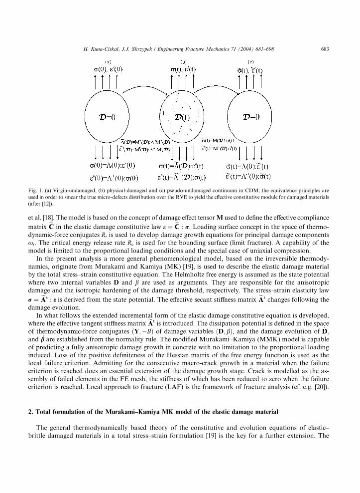
Fig. 1. (a) Virgin-undamaged, (b) physical-damaged and (c) pseudo-undamaged continuum in CDM; the equivalence principles are
used in order to smear the true micro-defects distribution over the RVE to yield the effective constitutive module for damaged materials
(after [12]).
H. Kuna-Ciskał, J.J. Skrzypek / Engineering Fracture Mechanics 71 (2004) 681–698 683
et al. [18]. The model is based on the concept of damage effect tensorM used to define the effective compliance
matrix eCC in the elastic damage constitutive law e ¼ eCC : r. Loading surface concept in the space of thermo-
dynamic-force conjugates Ri is used to develop damage growth equations for principal damage components
xi. The critical energy release rate Rc is used for the bounding surface (limit fracture). A capability of the
model is limited to the proportional loading conditions and the special case of uniaxial compression.
In the present analysis a more general phenomenological model, based on the irreversible thermody-
namics, originate from Murakami and Kamiya (MK) [19], is used to describe the elastic damage material
by the total stress–strain constitutive equation. The Helmholtz free energy is assumed as the state potential
where two internal variables D and b are used as arguments. They are responsible for the anisotropicdamage and the isotropic hardening of the damage threshold, respectively. The stress–strain elasticity law
r ¼ eKKs : e is derived from the state potential. The effective secant stiffness matrix eKKs changes following the
damage evolution.
In what follows the extended incremental form of the elastic damage constitutive equation is developed,
where the effective tangent stiffness matrix eKKt is introduced. The dissipation potential is defined in the space
of thermodynamic-force conjugates ðY;�BÞ of damage variables ðD; bÞ, and the damage evolution of _DD;and _bb are established from the normality rule. The modified Murakami–Kamiya (MMK) model is capable
of predicting a fully anisotropic damage growth in concrete with no limitation to the proportional loading
induced. Loss of the positive definiteness of the Hessian matrix of the free energy function is used as thelocal failure criterion. Admitting for the consecutive macro-crack growth in a material when the failure
criterion is reached does an essential extension of the damage growth stage. Crack is modelled as the as-
sembly of failed elements in the FE mesh, the stiffness of which has been reduced to zero when the failure
criterion is reached. Local approach to fracture (LAF) is the framework of fracture analysis (cf. e.g. [20]).
2. Total formulation of the Murakami–Kamiya MK model of the elastic damage material
The general thermodynamically based theory of the constitutive and evolution equations of elastic–brittle damaged materials in a total stress–strain formulation [19] is the key for a further extension. The
684 H. Kuna-Ciskał, J.J. Skrzypek / Engineering Fracture Mechanics 71 (2004) 681–698
Helmholtz free energy is a function of the elastic strain tensor ee, the second-rank damage tensor D, and
another scalar damage variable b, D ¼ DðD; bÞ. The following Helmholtz free energy decomposition into
the elastic and the damage terms is postulated as the state potential:
qwðee;D; bÞ ¼ qweðee;DÞ þ qwdðbÞ ð1Þ
According to the representation theory of non-linear algebra, the most general form of a scalar function of
the second-rank tensors weðee;DÞ can be expressed as the combination of 10 basic invariants of the tensorsee, D (cf. [21–23]):
we ¼ wefTr ee;TrðeeÞ2;TrðeeÞ3;TrD;TrðDÞ2;TrðDÞ3;TrðeeDÞ;Tr½ðeeÞ2D;Tr½eeðDÞ2;Tr½ðeeÞ2ðDÞ2gð2Þ
However, at the initial elastic state, the elastic behaviour is isotropic linear, hence the Helmholtz free energyqweðee;DÞ is quadratic with respect to ee. Additionally, since qweðee;DÞ will decrease with damage growth, it
is supposed to be linear in D (cf. [19,24]). Eventually, the simplified representation of the function qweðee;DÞcan be used, which depends on the five basic invariants of ee and D, as a linear combination of the following
terms:
ðTr eeÞ2;TrðeeÞ2; ðTr eeÞ2TrD;TrðeeÞ2TrD;Tr eeTrðeeDÞ;Tr½ðeeÞ2D
In order to properly describe the unilateral damage response in tension or compression a modified elastic
strain tensor ee in the principal strain co-ordinate system is defined
eI ¼ heIi � fh�eIi ¼ kðeIÞeI ; f 2 h0; 1i;kðeIÞ ¼ kI ¼ HðeIÞ þ fHð�eIÞ; I ¼ 1; 2; 3
ð3Þ
Symbol h i denotes the Macauley bracket, Hð Þ is the Heaviside step function, eI ðI ¼ 1; 2; 3Þ are principal
values of ee, and f is an additional material constant responsible for the unilateral damage response effect
under tension or compression (cf. [25]). For f ¼ 1 the modified strain tensor ee is identical to ee and the
unilateral damage (crack opening/closure) effect is not accounted for. In contrast, for f ¼ 0, the strain
tensor ee is modified in such a way that negative principal strain components are replaced by zeros, whereas
positive ones remain unchanged.In the general co-ordinate system the modified strain tensor is expressed as follows (cf. [24]):
eij ¼X3
I¼1
eI QIiQIj ¼X3
I¼1
kðeIÞeIQIiQIj ¼ Bijklekl ð4Þ
where
Bijkl ¼X3
I¼1
kðeIÞQIiQIjQIkQIl ð5Þ
is the fourth-rank tensor built of direction cosines between the principal strain axes and the current spatial
system.
Following Murakami and Kamiya [19] assumptions, both terms of the free energy (2) are represented as:
qweðee;DÞ ¼ 1
2kðTr eeÞ2 þ lTrðeeÞ2 þ g1ðTr eeÞ2TrDþ g2TrðeeÞ2TrD
þ g3Tr eeTrðeeDÞ þ g4Tr½ðeeÞ2D; qwdðbÞ ¼ 1
2Kdb
2 ð6Þ

H. Kuna-Ciskał, J.J. Skrzypek / Engineering Fracture Mechanics 71 (2004) 681–698 685
where k and l are Lam�ee constants for undamaged materials, g1, g2, g3, g4, and Kd are material constants.
Note that the modified strain tensor ee is applied in the last term of we exclusively, which ensures the
continuous transition of the stress–strain response from crack opening to closure (cf. [26,27]). In general, it
may be shown that the unilateral crack opening/closure effect can influence only the diagonal componentsof the stiffness matrix Ks
ii, if the constitutive law is written in the principal damage directions (cf. [26]). The
unilateral damage takes place during unloading when e ¼ 0 or r ¼ 0. In compression the initial stiffness is
partially recovered, depending on the parameter f (3). It may be shown that in the case considered, when
only the last term in (6) is affected by the unilateral damage, the non-diagonal terms Ksijði 6¼ jÞ are not
modified by the active/passive unilateral condition (cf. [28]).
The following constitutive equation of anisotropic elasticity coupled with damage is furnished from (6)
according to the conventional procedure of the thermodynamic formalism
Fig. 2.
force c
r ¼ oðqwÞoee
¼ ½kðTr eeÞ þ 2g1ðTr eeÞðTrDÞ þ g3TrðeeDÞIþ 2½l þ g2ðTrDÞee
þ g3TrðeeÞDþ g4ee :
oee
oeeD
�þD
oee
oee
�ð7Þ
where oee=oee is the fourth-rank tensor derived from (4) and (5).
The thermodynamic-force conjugates of D and b are also derived from (6)
Y ¼ �qowoD
¼ �½g1ðTreeÞ2 þ g2ðTrðeeÞ2I� g3ðTreeÞee � g4eeee;
B ¼ qowd
ob¼ Kdb
ð8Þ
The damage dissipation potential in the space of force conjugates fY;�Bg is assumed in the form
F ðY;BÞ ¼ Yeq � ðB0 þ BÞ ¼ 0; Yeq ¼ffiffiffiffiffiffiffiffiffiffiffiffiffiffiffiffiffiffiffiffi12Y : L : Y
q; Lijkl ¼ 1
2ðdikdjl þ dildjkÞ ð9Þ
where B0 and B stand for the initial damage threshold and the subsequent damage force conjugates of b,respectively. Hence, experimentally motivated by Murakami and Kamiya [19] the isotropic hardening of
damage dissipation surface (9) in the fY;Bg space is introduced, as sketched in Fig. 2. Note that inside the
damage dissipation surface the damage evolution does not occur. A damage threshold hardening effect
Initial and subsequent damage dissipation surfaces and illustration of the normality rule in the fY;Bg space of thermodynamic-
onjugates of fD; bg.

686 H. Kuna-Ciskał, J.J. Skrzypek / Engineering Fracture Mechanics 71 (2004) 681–698
results from the micro-mechanical response in concrete. The pre-load micro-cracks initially activated under
applied loading, might further be arrested when the obstacles are met.
The damage evolution equations are finally established from the normality rule
Fig. 3.
after M
_DD ¼ _kkd
oFoY
; _bb ¼ _kkd
oFoð�BÞ ¼
_kkd ð10Þ
and the consistency condition _FF ¼ 0 ¼ oFoY
: _YYþ oFoB
_BB is used to eliminate _kkd from (10)
_kkd ¼aoFoY
: _YY
oBob
¼ aL : Y
2KdYeq
: _YY ð11Þ
A factor a ¼ 1 or a ¼ 0 is used for the active or passive damage growth, respectively.
When exposed to tension or compression, the MK constitutive phenomenological model is capable of
capturing unilateral damage response. Under the uniaxial tension condition the damage component D11 is
dominant, whereas the other two components D22 and D33 are negligible. By contrast, under the uniaxialcompression the transverse damage components D22 ¼ D33 become predominant, but a non-negligible axial
component D11 is also visible (cf. Fig. 3). In contrast to other models that are time-dependent (cf. e.g. [9]),
damage evolution described by the MK model results from the stress and strain growth, but it is time-
independent and does not occur under the constant stress condition. Note also that in the MK model below
the damage threshold A0ðr0; e0Þ none damage nucleation or growth occurs. On the non-linear pre-peak
stress–strain curve the damage evolution cause the elastic modulus in the constitutive equation to drop,
until the critical point in a sense of the material instability in the r–e curve Afðrf ; efÞ is met and, hence, the
local failure criterion is satisfied.
ε11ε11
ε11
ε0 ε0 εr
εr
εr εrε0
σ 11[M
Pa]
σ 11[M
Pa]
D11
D =D22 33
0 0-5 -10 -15 -20 -25
-10
-20
-30
-40
-50
00
2
0.05
2
2
4
0.10
4
4
6
0.15
6
6
10-4
10-4
10-410-4
8
0.20
10
0.25
xx
x
AfAf
A0
A0
(a) (b)
ε11
ε0
D11
D =D22 33
-50
0.04
0.08
0.12
0.16
0.20
0.24
-10 -15 -20 -25x
σ
σ
σ
σ
Stress–strain curves and damage growth in a concrete specimen under the uniaxial tension or the uniaxial compression tests,
urakami and Kamiya [19].

Fig. 4. Stress–strain loops in the elastic damage material under cyclic uniaxial loading conditions; upper index ‘‘i’’ denotes the number
of loading cycle, i ¼ 1; 2; 3; . . ., lower index ‘‘0’’ corresponds to the damage threshold.
H. Kuna-Ciskał, J.J. Skrzypek / Engineering Fracture Mechanics 71 (2004) 681–698 687
To illustrate this behaviour the numerical simulation of the damage response under the uniaxial tensionand compression was performed by Murakami and Kamiya [19]. The model was calibrated for a high
strength concrete to yield the following set of material constants
E ¼ 21:4 ½GPa; v ¼ 0:2; g1 ¼ �400 ½MPa; g2 ¼ �900 ½MPa; g3 ¼ 100 ½MPa;g4 ¼ �23500 ½MPa; f ¼ 0:1; Kd ¼ 0:04 ½MPa; B0 ¼ 0:0026 ½MPa
ð12Þ
Under the cyclic loading condition a cycle-by-cycle softening of the material follows the damage evo-
lution. It is accompanied by the damage threshold increase from cycle to cycle ri0, and a simultaneous
critical stresses rimax drop until, after a number of cycles, the failure criterion is met at the critical point
Afðrf ; efÞ (Fig. 4). In the case of uniaxial stress state considered the critical point (failure) corresponds to the
maximum at the stress–strain curve.
In the original paper by Murakami and Kamiya [19] it is assumed that the failure criterion corresponds
to the critical eigenvalue of damage Dimax ¼ Dcrit which has been established at the level of Dcrit ¼ 0:4.However, in a general case, the critical damage value at the critical point changes with the loading tra-jectory and, hence, the concept of constant critical damage Dcrit cannot be used as the failure criterion. In a
multiaxial case the more general failure criterion has to be formulated that requires the Hessian matrix of
the function w is positive definite (see Section 3). To this end the incremental form of the constitutive
equation of the elastic damage material has to be developed.
3. Incremental formulation of the modified Murakami–Kamiya MMK model and failure criterion
When the total formulation is used the constitutive equation (7) represents stress–strain relations by the
use of the secant elastic damage stiffness eKKsðDÞ that suffers from damage evolution in a material
r ¼ eKKs : ee or rij ¼ eKKsijkl : eekl ð13Þ
The incremental form of the stress–strain relations may be established from (13) as follows:
dr ¼ eKKs : dee þ ee :oeKKs
oD: dD
!ð14Þ

688 H. Kuna-Ciskał, J.J. Skrzypek / Engineering Fracture Mechanics 71 (2004) 681–698
The damage increment dD on dee is obtained from (10) and (11). Eventually, the following incremental
state equation is derived (cf. [28,29])
dr ¼ eKKs þ aee :oeKKs
oD:
YY :oY
oee
4KdY 2eq
0B@1CA
264375 : dee ð15Þ
The square bracket in (15) represents the effective tangent stiffness eKKtðee;DÞ and factor a equal 0 or 1 is used
for passive or active damage process, respectively. By the use of Voigt notation the state equations, total
(13) and incremental (15), may easily be rewritten in a more convenient matrix forms:
frg ¼ ½eKKsðDÞfeeg or ri ¼ eKKsije
ej ð16Þ
fdrg ¼ ½eKKtðee;DÞfdeeg orri ¼ eKKtijdeej ð17Þ
Note that superscript lower case ‘‘t’’ is used for the tangent stiffness matrix, and should not be confused
with the transposition operator ‘‘T’’. In a general 3D case the following matrix representation of the total
constitutive equation holds
r11
r22
r33
r23
r31
r12
8>>>>>><>>>>>>:
9>>>>>>=>>>>>>;¼
eKKs11
eKKs12
eKKs13
eKKs14
eKKs15
eKKs16eKKs
22eKKs
23eKKs
24eKKs
25eKKs
26eKKs33
eKKs34
eKKs35
eKKs36eKKs
44eKKs
45eKKs
46
sym: eKKs55
eKKs56eKKs66
2666666664
3777777775
e11e22e33c23c31c12
8>>>>>><>>>>>>:
9>>>>>>=>>>>>>;ð18Þ
The ‘‘full’’ 6� 6 symmetric secant stiffness matrix is furnished as follows:
eKKs11 ¼ k þ 2l þ 2ðg1 þ g2ÞTrDþ 2ðg3 þ g4ÞD11eKKs22 ¼ k þ 2l þ 2ðg1 þ g2ÞTrDþ 2ðg3 þ g4ÞD22eKKs33 ¼ k þ 2l þ 2ðg1 þ g2ÞTrDþ 2ðg3 þ g4ÞD33eKKs12 ¼ k þ 2g1TrDþ g3ðD11 þ D22Þ; eKKs13 ¼ k þ 2g1TrDþ g3ðD11 þ D33ÞeKKs23 ¼ k þ 2g1TrDþ g3ðD22 þ D33ÞeKKs44 ¼ 0:5½2l þ 2g2TrDþ g4ðD33 þ D22Þ; eKKs
45 ¼ g4D12eKKs55 ¼ 0:5½2l þ 2g2TrDþ g4ðD11 þ D33Þ; eKKs
46 ¼ g4D13eKKs66 ¼ 0:5½2l þ 2g2TrDþ g4ðD11 þ D22Þ; eKKs
56 ¼ g4D23eKKs14 ¼ g3D23; eKKs
24 ¼ eKKs34 ¼ ðg3 þ g4ÞD23eKKs
25 ¼ g3D13; eKKs15 ¼ eKKs
35 ¼ ðg3 þ g4ÞD13eKKs36 ¼ g3D12; eKKs
16 ¼ eKKs26 ¼ ðg3 þ g4ÞD12
ð19Þ
Let us mention that the above general formulae are derived for a special case f ¼ 1, where ee � ee (the
unilateral damage effect is ignored in (19)). Representation of the effective tangent stiffness matrix in a
general 3D state is rather cumbersome hence, in what follows, we confine ourselves to the simpler plane
stress state.In the case if incremental form of the constitutive law is used (17) the (6� 6) matrix representation can
be written as follows:
H. Kuna-Ciskał, J.J. Skrzypek / Engineering Fracture Mechanics 71 (2004) 681–698 689
dr11
dr22
dr33
dr23
dr31
dr12
8>>>>>><>>>>>>:
9>>>>>>=>>>>>>;¼
o2woe211
o2woe11oe22
o2w
oe11oe33o2w
oe11oc23
o2woe11oc31
o2woe11oc12
o2woe222
o2woe22oe33
o2woe22oc23
o2woe22oc31
o2woe22oc12
o2woe233
o2woe33oc23
o2woe33oc31
o2woe33oc12
o2woc223
o2woc23oc31
o2woc23oc12
sym:o2woc231
o2woc31oc12o2woc212
2666666666666666666666664
3777777777777777777777775
de11de22de33dc23dc31dc12
8>>>>>><>>>>>>:
9>>>>>>=>>>>>>;ð20Þ
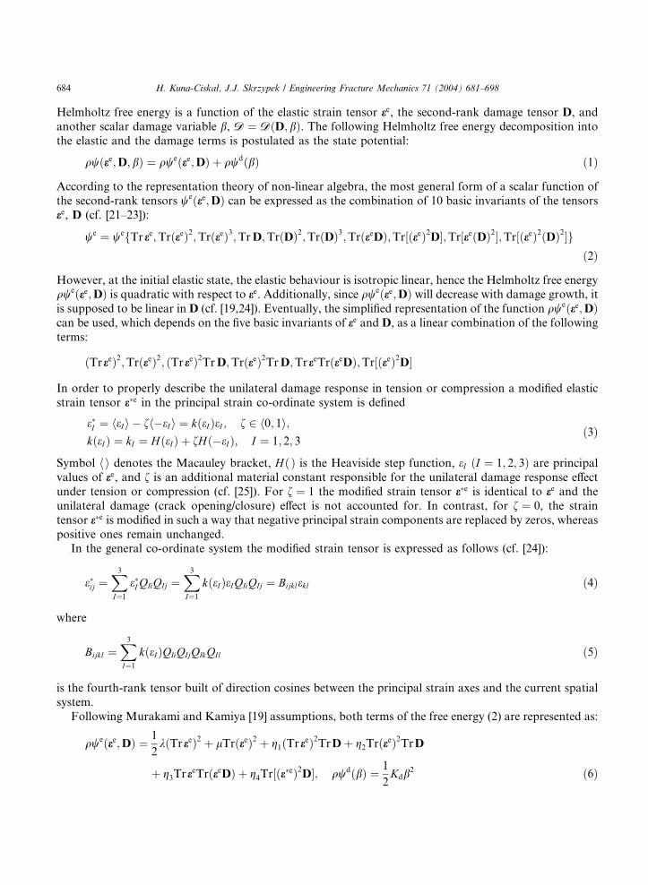
The (6� 6) matrix of the components of the fourth-rank tensor Hijkl ¼ o2w=oeijoekl is known as the Hessian
matrix of the function w. In order to introduce the general failure criterion the Drucker�s material stability
postulate is adopted:
drijdeij > 0 ð21Þ
Substituting for drij formula (20) into the stability criterion (21) we obtain
o2woeijoekl
deijdekl ¼ Hijkldeijdekl > 0 ð22Þ
The quadratic form ðo2w=oeijoeklÞdeijdekl must be positive definite for arbitrary values of the components
deij, hence, eventually the condition (22) requires that Hessian matrix ½H be positive definite (cf. [30]).
According to the Sylvester criterion the symmetric matrix ½H of the nth order is positive definite if and only
if
det½Hk > 0 ðk ¼ 1; 2; . . . ; nÞ ð23Þ
where ½Hk is the (k � k) minor of the matrix ½H (cf. [31]).The local tangent stiffness matrix is used for the quasi-Newton algorithm for first iteration step of solving
the non-linear equation (17) as long as the local failure criterion (23) holds. The stiffness of the element in
the FE mesh that has come to failure is next reduced to zero. As a consequence, the failed element is
completely released from stress and the appropriate stress redistribution occurs in the neighbouring ele-
ments to ensure the global equilibrium. Note that the above failure criterion (23) assumes the brittle failure
mechanism. However, when broader class of materials is considered, a post-peak softening regime can also
be admitted, that would result in strain localisation and a smooth stiffness drop in elements that come to
failure. Neglecting the effect of visco-plastic deformation on the energy dissipation in the MMK modelconsidered might be inconsistent with the post-peak analysis and, hence, the additional brittle fracture
criterion is necessary to use.
By the use of local approach to fracture LAF, based on FEM and CDM, the crack is modelled as the
assembly of failed elements in the mesh. Subsequent elements in the FE mesh that have come to failure
(along the crack) are released from stresses and the appropriate redefinition of the global stiffness of the
structure occurs. The procedure is continued as long as the overall fracture mechanism of the structure is
reached. The described method of LAF is capable of predicting the fracture initiation and the ultimate
fracture pattern, as well as the limit load that corresponds to the considered fracture mechanism in astructure. The crack growth stage and the ultimate crack pattern are, in general, mesh-dependent. To
690 H. Kuna-Ciskał, J.J. Skrzypek / Engineering Fracture Mechanics 71 (2004) 681–698
mitigate the effect of element size and shape the additional regularisation procedures are required. To this
end, the thermodynamic-force conjugate Y can be subjected to a non-local treatment bYY by applying the
formula analogous to that described in Skrzypek et al. [32] where the non-local and limited stress variable
was defined for the Litewka model. The regularisation applied in [32] allowed to avoid mesh effect andobtain the convergent solution with respect to the element size and shape. In present case the following
formula for the non-local variable bYY can be used:
bYYðxÞ ¼ RXdYðnÞuðx; nÞdXdRXd
uðx; nÞdXd
; uðx; nÞ ¼ exp
"� dðx; nÞ
d
� �2#
ð24Þ
Additionally, to avoid the singularity of Y at the crack tip when the mesh size tends to zero, the cut-off
procedure should be used in the neighbourhood of a crack tip according to the scheme
Y ¼ kY; k ¼ 1 if Yeq 6 Yu
Yu=Yeq if Yeq > Yu
ð25Þ
where the cut-off factor is determined from (9) as follows:
k ¼ Yu
Yeq
¼ B0 þ BYeq
ð26Þ
In the examples presented below the regularisation has not been used. The results obtained for crack
prediction exhibit the mesh effect, so that a non-local treatment has to be involved in order to ensure
convergence.
4. Matrix constitutive equations in plane stress state
The effective application of (4) to the constitutive equation (7) requires the explicit formula for the
derivative oee=oee which accounts for the unilateral opening/closure effect. To this end the unilateral
transformation matrix Bijkl (5) must explicitly be expressed. In the case of plane stress considered the
transformation reduces to the plain rotation by the angle a
a ¼ 1
2arctg
2e12e11 � e22
ð27Þ
such that the derivative oee=oee must be calculated according to the procedure for the complex function
oeijoekl
¼ Bijkl þoBijpq
oaoaoekl
epq ð28Þ
The above scheme is cumbersome in the numerical applications. In a particular case of plane stress state,
when the rotation angle a is small, Eq. (5) may be reduced to the simplified form
e11e22e12e33
8>><>>:9>>=>>; ¼
a 0 b 0
0 c b 0
0:5b 0:5b d 0
0 0 0 1
26643775
e11e22e12e33
8>><>>:9>>=>>; ð29Þ
where
a ¼ 1
2ðk1 þ k2Þ þ
1
2ðk1 � k2Þ cos 2a; b ¼ 1
2ðk1 � k2Þ sin 2a
c ¼ 1
2ðk1 þ k2Þ �
1
2ðk1 � k2Þ cos 2a; d ¼ 1
2ðk1 þ k2Þ
ð30Þ

H. Kuna-Ciskał, J.J. Skrzypek / Engineering Fracture Mechanics 71 (2004) 681–698 691
When the assumption of plane stress is used r33 ¼ 0 the total form of the matrix constitutive equations
(18) reduces to
r11
r22
0
r12
8>><>>:9>>=>>; ¼
eKKs11
eKKs12
eKKs13
eKKs16eKKs
12eKKs
22eKKs
23eKKs
26eKKs13
eKKs23
eKKs33
eKKs36eKKs
16eKKs
26eKKs
36eKKs
66
2666437775
e11e22e33c12
8>><>>:9>>=>>; ð31Þ
where the symmetric 4� 4 effective secant stiffness matrix, which depends on D, is furnished as follows:
eKKs11 ¼ k þ 2l þ 2ðg1 þ g2ÞTrDþ 2g3D11 þ g4 D11 2a2
� þ 1
2b2
�þ 1
2D22b2 þ 2abD12
!eKKs
22 ¼ k þ 2l þ 2ðg1 þ g2ÞTrDþ 2g3D22 þ g4
1
2b2D11
þ D22 2c2
�þ 1
2b2
�þ 2bcD12
!eKKs
33 ¼ l þ g2TrDþ 12g4fðD11 þ D22Þðb2 þ d2Þ þ 4D12bdgeKKs
12 ¼ eKKs21 ¼ k þ 2g1TrDþ g3ðD11 þ D22Þ þ g4
12b2ðD11
"þ D22Þ þ D12bðaþ cÞ
#eKKs
13 ¼ eKKs31 ¼ g3D12 þ 1
2g4fD11bð2aþ dÞ þ bdD22 þ 2D12ðb2 þ adÞgeKKs
23 ¼ eKKs32 ¼ g3D12 þ 1
2g4fbdD11 þ D22bð2cþ dÞ þ 2D12ðb2 þ cdÞgeKKs
16 ¼ eKKs61 ¼ g3D12 þ 1
2g4½D11bð2aþ dÞ þ bdD22 þ 2D12ðb2 þ adÞeKKs
26 ¼ eKKs62 ¼ g3D12 þ 1
2g4½bdD11 þ D22bð2cþ dÞ þ 2D12ðb2 þ cdÞeKKs
36 ¼ eKKs63 ¼ g3D12eKKs
66 ¼ l þ g2TrDþ 12g4½ðD11 þ D22Þðb2 þ d2Þ þ 4D12bd
ð32Þ
Thermodynamic-force conjugates Y and B are defined by (8) as follows:
Y11
Y22
Y33
Y23
Y31
Y12
8>>>>>><>>>>>>:
9>>>>>>=>>>>>>;¼
�g1ðTr eeÞ2 � g2TrðeeÞ2 � g3ðTr eeÞe11 � g4½ðae11 þ be12Þ2 þ ð0:5bðe11 þ e22Þ þ de12Þ2�g1ðTr eeÞ2 � g2TrðeeÞ2 � g3ðTr eeÞe22 � g4½ðce22 þ be12Þ2 þ ð0:5bðe11 þ e22Þ þ de12Þ2
�g1ðTr eeÞ2 � g2TrðeeÞ2 � g3ðTr eeÞe33 � g4k23e
233
0
0�g3ðTr eeÞe12 � g4ð0:5bðe11 þ e22Þ þ de12Þðae11 þ 2be12 þ ce22Þ
8>>>>>><>>>>>>:
9>>>>>>=>>>>>>;ð33Þ
B ¼ Kdb ð34Þ
where
Tr ee ¼ ðe11 þ e22Þ½2l þ 2g2TrDþ ðg3 þ 2g4k23ÞD33 � g3ðD11e11 þ D22e22 þ 2D12e12Þ
k þ 2l þ 2ðg1 þ g2ÞTrDþ 2ðg3 þ g4k23ÞD33
ð35Þ
Note that the 4� 4 secant stiffness matrix eKKsðDÞ may further be reduced to 3� 3 one by eliminating e33from (31).
When the general incremental form of the constitutive equations (17) is applied to plane stress dr33 ¼ 0,
the following 4� 4 tangent stiffness matrix representation eKKtijðee;DÞ is furnished in terms of the corre-
sponding secant matrix components and the additional terms depending on damage and strain tensors (15)

692 H. Kuna-Ciskał, J.J. Skrzypek / Engineering Fracture Mechanics 71 (2004) 681–698
dr11
dr22
0dr12
8>><>>:9>>=>>; ¼
eKKt11
eKKt12
eKKt13
eKKt16eKKt
12eKKt
22eKKt
23eKKt
26eKKt13
eKKt23
eKKt33
eKKt36eKKt
16eKKt
26eKKt
36eKKt
66
2666437775
de11de22de33dc12
8>><>>:9>>=>>; ð36Þ
For instance, when the first element of the matrix (36) is concerned, the following formula holds:
eKKt11 ¼ eKKs
11 þ e11 2ðg1
þ g2Þ
oD11
oe11
�þ oD22
oe11þ oD33
oe11
�þ 2g3
oD11
oe11þ g4
oD11
oe11ð2a2
$þ 0:5b2Þ
þ 0:5b2 oD22
oe11þ 2ab
oD12
oe11
%!þ e22 2g1
oD11
oe11
� þ oD22
oe11þ oD33
oe11
�þ g3
oD11
oe11
�þ oD22
oe11
�þ g4 0:5b2 oD11
oe11
�$þ oD22
oe11
�þ bðaþ cÞ oD12
oe11
%!þ e33 2g1
oD11
oe11
� þ oD22
oe11þ oD33
oe11
�þ g3
oD11
oe11
�þ oD33
oe11
�!þ c12 g3
oD11
oe11
þ 0:5g4 bð2a
$þ dÞ oD11
oe11þ bd
oD22
oe11þ 2ðb2 þ adÞ oD12
oe11
%!
ð37ÞOther elements of the matrix (36) can be established in a similar fashion, when the general equation (15) is
used. Also in this case de33 can be eliminated from (36) to reduce the tangent stiffness matrix to the 3� 3
one.
5. Numerical simulation of damage and fracture in concrete
5.1. Micro-mechanical observations
Concrete is a strongly heterogeneous engineering material where initial (pre-load) micro-cracks, which
are most frequently located at the cement matrix–aggregate interfaces, are randomly oriented with respect
to the load direction (cf. e.g. [1]).
When the tensile load is applied to the concrete specimen the micro-cracks that are oriented per-pendicularly to the load axis start to open and grow until the adjacent micro-cracks bridge is formed.
Eventually, when the fracture toughness of the matrix is exceeded, micro-cracks coalesce to form the
macro-crack (see also, [5]). Preferable orientation of the macro-crack is also, roughly speaking, perpendicular
to the tensile load axis. If the obstacle does not arrest it, a final transverse splitting of the specimen is met.
Note, however, that not only perpendicular micro-cracks come to grow under tension. Also micro-cracks
that are inclined at a certain angle to the tensile direction may grow to form a kinked-type micro-crack as
shown in Fig. 5(a). Corresponding stress–strain curve in tension exhibits three stages that correspond to
linear elastic, hardening and softening regime.Damage response of concrete under compression exhibits: the gradual degradation of elastic module
after the damage threshold from linear elastic behaviour is reached, the positive dilatancy due to consec-
utive opening of micro-cracks, the anisotropy of micro-crack evolution, and the existence of softening
regime. The final failure that corresponds to macro-crack formation in compression occurs at the stress
much higher than that at which the individual micro-crack can be activated. Micro-mechanical mechanism
of damage and fracture in compression is much more complex than in tension, and the effect of micro-
cracks interaction is much stronger. Sliding micro-crack mechanism plays here the essential role. Consider a
single pre-load micro-crack inclined to the compressive direction at a certain angle, Fig. 5(b) (cf. [4], also[1]). During the first phase a frictional sliding along the faces of the pre-load micro-crack occurs with no

Fig. 5. (a) Simplified macro-crack growth under tension (after [3]) and (b) sliding crack mechanism with the actual and the simplified
geometry of tensile wing cracks (after [2]).
H. Kuna-Ciskał, J.J. Skrzypek / Engineering Fracture Mechanics 71 (2004) 681–698 693
length change of it, when the actual shear stress at a point of micro-crack face exceeds the resistance of
friction. When the elastic energy release rate G at the crack tip reaches the critical value, the second phase
occurs when a secondary curvilinear tensile-type wing micro-crack starts to open at each crack-tip. Next,following a path for which the stress intensity factor KI reaches a maximal value (or KII ¼ 0) the wing
micro-crack grows, gradually changing its initial direction, such that eventually it coincides with the
compressive load axis. Final failure mechanism in compression results from a coalescence and interaction
of the wing micro-cracks to finally form an axial splitting of the specimen or a shear fracture at small
confinement or a pseudo-ductile failure at large confinement (cf. Basista [5]). Motivated by the above
micro-mechanical evidence of damage in concrete, Basista and Gross [3] developed the simplified models of
the kinked micro-crack growth under biaxial tension as well as a simplified model of the sliding micro-crack
under compression [4]. Finally the non-linear macroscopic stress–strain relationships were obtained, wherethe Rice internal variable theory, based on the micro-to-macro transition, was used as a constitutive
framework.
In what follows, damage and failure mechanisms in concrete are studied by the use of the continuum
damage mechanics (CDM), modified Murakami–Kamiya (MMK) constitutive model, and the local ap-
proach to fracture (LAF). The material constants used to the model calibration for the high strength
concrete are given by (12). All the numerical calculations were performed by the use of the ABAQUS
system.
5.2. Failure mechanism in a 2D structure with the pre-load crack in tension
Consider the plane-stress concrete structure with the pre-load crack of the infinitely small width, inclined
at the angle of 45� to the tension direction. Structure is subject to the uniform tension at top and bottomedges, and is free to move at all sides, Fig. 6. The monotonically increasing tensile load q causes the pre-load
crack of the zero width in a pre-load state, to open. Stress concentration at the zones neighbouring crack
tips is accompanied by the cumulation of the D11 damage component in the element where the secondary
kinked crack starts to open when the failure criterion (23) is locally met. The magnitudes and directions of

Fig. 6. A plane stress concrete structure with the pre-load inclined crack, subjected to tension in the direction (1): (a) the geometry and
mesh, (b) maximal principal stress distribution in the surrounding of the pre-load crack tip; the arrows represent the actual principal
stresses.
694 H. Kuna-Ciskał, J.J. Skrzypek / Engineering Fracture Mechanics 71 (2004) 681–698
the principal stress components in elements neighbouring crack tip are sketched in Fig. 6 just before the
instant of the secondary kinked crack opening. The magnified square zone neighbouring the pre-load crack
tip is shown in Fig. 6(b), where the magnifications factor for displacements equal 100 is used for figure
clarity.
With the increasing tensile load the consecutive elements come to failure, to ultimately form a ‘‘kinked’’
crack that splits the concrete specimen approximately perpendicularly to the tension direction, as shown in
Fig. 7(a)–(c). Note releasing the elements neighbouring the crack face from stresses following the kinked
crack growth. Anisotropic damage growth and fracture mechanism in a specimen causes on a final stage theoverall stiffness of the structure to drastically drop. The predicted critical load for crack initiation qf
1 differs
from that of ultimate failure qfu by the amount of approximately 15%.
A qualitatively similar kinked crack in a brittle rock-like specimen was predicted by Basista [5], where
the micro-mechanical damage model (MD) was used on the micro-level.
Fig. 7. Formation of the ‘‘kinked-type’’ crack under tension; maximal principal stress distribution on different stages of crack
propagation.
H. Kuna-Ciskał, J.J. Skrzypek / Engineering Fracture Mechanics 71 (2004) 681–698 695
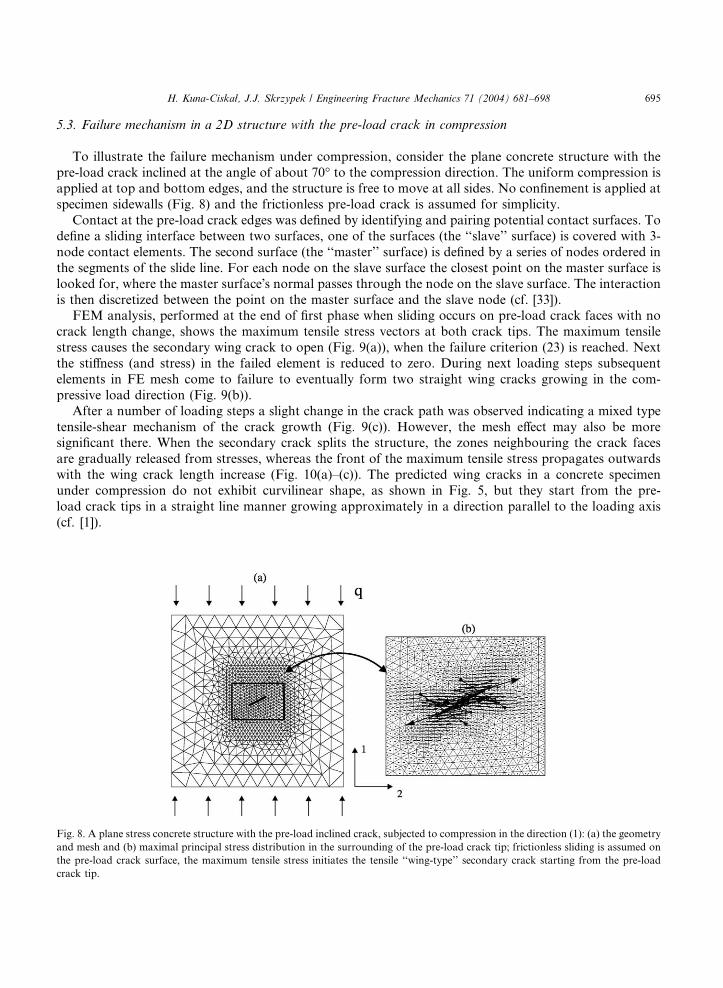
5.3. Failure mechanism in a 2D structure with the pre-load crack in compression
To illustrate the failure mechanism under compression, consider the plane concrete structure with the
pre-load crack inclined at the angle of about 70� to the compression direction. The uniform compression isapplied at top and bottom edges, and the structure is free to move at all sides. No confinement is applied at
specimen sidewalls (Fig. 8) and the frictionless pre-load crack is assumed for simplicity.
Contact at the pre-load crack edges was defined by identifying and pairing potential contact surfaces. To
define a sliding interface between two surfaces, one of the surfaces (the ‘‘slave’’ surface) is covered with 3-
node contact elements. The second surface (the ‘‘master’’ surface) is defined by a series of nodes ordered in
the segments of the slide line. For each node on the slave surface the closest point on the master surface is
looked for, where the master surface�s normal passes through the node on the slave surface. The interaction
is then discretized between the point on the master surface and the slave node (cf. [33]).FEM analysis, performed at the end of first phase when sliding occurs on pre-load crack faces with no
crack length change, shows the maximum tensile stress vectors at both crack tips. The maximum tensile
stress causes the secondary wing crack to open (Fig. 9(a)), when the failure criterion (23) is reached. Next
the stiffness (and stress) in the failed element is reduced to zero. During next loading steps subsequent
elements in FE mesh come to failure to eventually form two straight wing cracks growing in the com-
pressive load direction (Fig. 9(b)).
After a number of loading steps a slight change in the crack path was observed indicating a mixed type
tensile-shear mechanism of the crack growth (Fig. 9(c)). However, the mesh effect may also be moresignificant there. When the secondary crack splits the structure, the zones neighbouring the crack faces
are gradually released from stresses, whereas the front of the maximum tensile stress propagates outwards
with the wing crack length increase (Fig. 10(a)–(c)). The predicted wing cracks in a concrete specimen
under compression do not exhibit curvilinear shape, as shown in Fig. 5, but they start from the pre-
load crack tips in a straight line manner growing approximately in a direction parallel to the loading axis
(cf. [1]).
Fig. 8. A plane stress concrete structure with the pre-load inclined crack, subjected to compression in the direction (1): (a) the geometry
and mesh and (b) maximal principal stress distribution in the surrounding of the pre-load crack tip; frictionless sliding is assumed on
the pre-load crack surface, the maximum tensile stress initiates the tensile ‘‘wing-type’’ secondary crack starting from the pre-load
crack tip.

Fig. 9. Formation of the ‘‘wing-type’’ crack under compression; subsequent stages of the macro-crack growth.
Fig. 10. Maximal principal stress distribution on several stages of the ‘‘wing-type’’ crack growth under compression.
696 H. Kuna-Ciskał, J.J. Skrzypek / Engineering Fracture Mechanics 71 (2004) 681–698
6. Final remarks
1. Phenomenological CDM based MK model is capable of predicting anisotropic damage growth in a con-
crete specimen under monotonic or cyclic loading conditions.
2. When solving the non-linear elastic damage problem the incremental stress–strain matrix constitutive
equation of the modified Murakami–Kamiya MMK model is necessary to use to ensure the convergence.
Loss of the positive definiteness of the tangent stiffness matrix is used as the failure criterion. To this end,
the set of sub-determinants of the Hessian matrix of the free energy function is checked at every integra-tion point, at each step of loading. This criterion is more general than the criterion proposed in [19].
3. By the use of local approach to fracture LAF and FEM the crack growth in a concrete specimen may
successfully be simulated until the ultimate fracture mechanism is achieved. Crack is modelled as the as-
sembly of failed elements in the FE mesh the stiffness of which and stress are reduced to zero.
4. Crack opening/closure effect is included in the model by introducing a modified strain tensor to the con-
stitutive law. The modification of the diagonal components of the elastic stiffness matrix by the active-
passive unilateral damage satisfies the continuity requirement during unloading, when e ¼ 0 or r ¼ 0.

H. Kuna-Ciskał, J.J. Skrzypek / Engineering Fracture Mechanics 71 (2004) 681–698 697
5. A concrete specimen with the pre-load crack fails in a different way under tension or compression. When
loaded by the axial tension, a ‘‘kinked-type’’ crack is formed in the direction perpendicular to the tension
axis. In contrast, when loaded by the axial compression, a slip on the primary crack faces results in a
‘‘wing-type’’ crack which starts from the primary crack tips and grows in the direction of axial compres-sion.
6. To properly model the sliding-type crack it is necessary to define the contact on the sliding surfaces. To
this end, the appropriate value of the sliding friction coefficient should be implemented. In the example
presented in this paper the frictionless sliding on the pre-load crack surfaces was assumed for simplicity.
7. The similarity between the fracture mechanisms in tension and compression on the micro-scale and the
corresponding fracture mechanisms on the macro-scale is shown. However, the mechanisms simulated
on the macro-scale are obtained for a single pre-load crack without the interaction effect between the
cracks considered. The procedure described in this paper may also be capable of predicting the final frac-ture pattern in the case of larger number of pre-load cracks.
8. Simulation of the crack propagation in the plane stress under tension or compression by the use of local
approach to fracture is capable of predicting crack pattern in a qualitative sense. The solution is, in gen-
eral, the mesh-dependent. In order to reduce mesh-dependence an additional regularisation treatment is
necessary. It may be done by the introduction of the non-local definition of the thermodynamic-force
conjugate Y and an additional cut-off procedure, in a similar fashion as it was done in [32].
Acknowledgements
The Grant 7T07A 03819 from the State Committee for Scientific Research KBN Poland is gratefully
acknowledged.
References
[1] Fanella D, Krajcinovic D. A micromechanical model for concrete in compression. Engng Fract Mech 1988;29:44–66.
[2] Basista M, Gross D. Internal variable representation of microcrack induced inelasticity in brittle materials. Int J Damage Mech
1997;6:300–16.
[3] Basista M, Gross D. A note on brittle damage description. Mech Res Commun 1989;16(3):147–54.
[4] Basista M, Gross D. The sliding crack model of brittle deformation: an internal variable approach. Int J Solids Struct 1998;5–
6:487–509.
[5] Basista M. Micromechanical and lattice modelling of brittle damage. Polish Academy of Science, Institute of Fundamental and
Technological Research, Warsaw, 3;2001.
[6] Krajcinovic D. Damage mechanics. Mech Mater 1989;8:117–97.
[7] Lacy TE, McDowell DL, Willice PA, Talreja R. On representation of damage evolution in continuum damage mechanics. Int J
Damage Mech 1997;1:62–5.
[8] Murakami S, Ohno N. A continuum theory of creep and creep damage. In: Creep in structures. Berlin: Springer-Verlag; 1981.
p. 442–4.
[9] Litewka A. Effective material constants for orthotropically damaged elastic solids. Arch Mech Stos 1985;37(6):631–42.
[10] Chaboche JL. Thermodynamically founded CDM models for creep and other conditions. In: Altenbach H, Skrzypek J, editors.
Creep and damage in materials and structures. New York: Springer-Vien; 1999. p. 209–83.
[11] Skrzypek JJ, Ganczarski A. Modeling of material damage and failure of structures. Heidelberg, Berlin: Springer; 1999.
[12] Skrzypek JJ. Material damage models for creep failure analysis and design of structures. In: Altenbach H, Skrzypek J, editors.
Creep and damage in materials and structures. New York: Springer-Vien; 1999. p. 97–166.
[13] Lemaitre J, Chaboche JL. Aspect phenomenologique de la rapture per endomagement. J M�eech Appl 1978;2:317–65.
[14] Simo JC, Ju JW. Strain- and stress-based continuum damage models. I––formulation, II––computational aspects. Int J Solids
Struct 1987;23:821–69.
[15] Cordebois JP, Sidoroff F. Damage induced elastic anisotropy. In: Col. EUROMECH 115, Villard de Land, 1979, also In: Boehler
JP, editor. Mechanical Behavior of Anisotropic Solids, Boston: Martinus Nijhoff; 1983. p. 761–74.
698 H. Kuna-Ciskał, J.J. Skrzypek / Engineering Fracture Mechanics 71 (2004) 681–698
[16] Chow CL, Lu TJ. An analytical and experimental study of mixed-mode ductile fracture under nonproportional loading. Int J
Damage Mech 1992;1:191–236.
[17] Chen HF, Chow CL. On damage strain energy release rate Y . Int J Damage Mech 1995;4:251–63.
[18] Al-Gadhib AH, Baluch MH, Shaalan A, Khan AR. Damage model for monotonic and fatigue response of high strength concrete.
Int J Damage Mech 2000;9(January):57–8.
[19] Murakami S, Kamiya K. Constitutive and damage evolution equations of elastic–brittle materials based on irreversible
thermodynamics. Int J Solids Struct 1997;39(4):473–86.
[20] Murakami S, Liu Y. Mesh-dependence in local approach to creep fracture. Int J Damage Mech 1995;4:230–50.
[21] Spencer AJM. Continuum Physics, vol. 1, part III, theory of invariants. New York–London, 1971.
[22] Rymarz Cz. Continuum Mechanics [in Polish], Wyd. Nauk. PWN Warszawa, 1993.
[23] Litewka A. Creep rupture of metals under multi-axial state of stress. Arch Mech 1989;41(1):3–23.
[24] Hayakawa K, Murakami S. Thermodynamical modeling of elastic–plastic damage and experimental validation of damage
potential. Int J Damage Mech 1997;6:333–63.
[25] Krajcinovic D. Damage Mechanics. Amsterdam: Elsevier; 1996.
[26] Chaboche JL. Development of continuum damage mechanics of elastic solids sustaining anisotropic and unilateral damage. Int J
Damage Mech 1993;2:311–29.
[27] Chaboche JL, Lesne PM, Maire JF. Continuum damage mechanics, anisotropy and damage deactivation for brittle materials like
concrete and ceramic composites. Int J Damage Mech 1995;4:5–21.
[28] Skrzypek J, Kuna-Ciskał H. Anisotropic Elastic–brittle-damage and fracture models based on irreversible thermodynamics. In:
Anisotropic Behaviour of Damaged Materials. Berlin: Springer; 2003.
[29] Kuna-Ciskał H, Skrzypek J. On local approach to fracture in a high strength concrete. In: Guagliano M, Aliabadi MH, editors.
Advances in Fracture and Damage Mechanics II. Geneva: Hoggar; 2001. p. 385–90.
[30] Chen WF, Han DJ. Plasticity for Structural Engineers. New York: Springer-Verlag; 1995.
[31] Bj€oorck A, Dahlquist G. Numerical Methods. Englewood Cliffs, NJ: Prentice-Hall; 1974.
[32] Skrzypek J, Kuna-Ciskał H, Ganczarski A. Computer simulation of damage and fracture in materials and structures under
thermo-mechanical loading. In: European congress on computational methods in applied sciences and engineering ECCOMAS
2000, 11–14 September, Barcelona; 2000 (CD).
[33] ABAQUS theory manual, Version 5.8. Hibbit, Karlsson & Sorensen; 1998.