#1 Rides Checklists - North Carolina · check gondola doors to operate and close smoothly without...
76
AVALANCHE WISDOM CHECK MAIN TRAILER LANDING GEAR FOR TIGHTNESS CHECK REAR OUTRIGGER SCREW JACKS FOR TIGHTNESS CHECK RIGHT FRONT OUTRIGGER SCREW JACK FOR TIGHTNESS CHECK ALL PLATFORM SCREW JACKS FOR SNUGNESS ENSURE ENTRANCE STEPS ARE CLEAR OF OBSTACLES CHECK ALL GATES FOR PROPER CLOSING AND LATCHING CHECK FOR PRESENCE OF “DANGER” SIGNS ON BACK OF RIDE CHECK TIE ROD ECCENTRIC ARMS FOR CRACKS OR BROKEN WELDS CHECK TIE ROD BEARING HOUSING FOR CRACKS CHECK TOWER SUPPORT ATTACHMENT AT FLOOR FOR CRACKS CHECK HYDRAULIC SYSTEM AND COMPONENTS FOR LEAKS OR DAMAGE CHECK FOR RETRACTED SET UP CYLINDER CHECK THATALL UPPER SCENERY IS PINNED TO THE SCENERY SUPPORT LADDERS CHECK THAT THE DIAGONAL SCENERY SUPPORT BRACES ARE INSTALLED AND SNUG CHECK THAT THE REAR SCENERY DIAGONAL TURNBUCKLES ARE SNUG AND INSTALLED CHECK THATALL BRACES FOR WING SCENERY IS INSTALLED AND R KEYED PERFORM INTERLOCK TEST WARNING! MAKE SURE NO ONE IS NEAR CARS OR BEHIND RIDE. CARS MAY MOVE UNEXPECTEDLY OR SUDDENLY. START HYDRAULIC PUMP. MOVE SPEED CONTROLKNOB IN ONE DIRECTION. RIDE SHOULD NOT MOVE. LEAVE CONTROL KNOB MOVED TILL END OF TEST TURN KEY OFF, RIDE OPERATE SWITCH TO STOP. RIDE SHOULD NOT MOVE. TURN KEY ON. RIDE SHOULD NOT MOVE. Page 1
Transcript of #1 Rides Checklists - North Carolina · check gondola doors to operate and close smoothly without...
AVALANCHE
WISDOM
� CHECK MAIN TRAILER LANDING GEAR FOR TIGHTNESS
� CHECK REAR OUTRIGGER SCREW JACKS FOR TIGHTNESS
� CHECK RIGHT FRONT OUTRIGGER SCREW JACK FOR TIGHTNESS
� CHECK ALL PLATFORM SCREW JACKS FOR SNUGNESS
� ENSURE ENTRANCE STEPS ARE CLEAR OF OBSTACLES
� CHECK ALL GATES FOR PROPER CLOSING AND LATCHING
� CHECK FOR PRESENCE OF “DANGER” SIGNS ON BACK OF RIDE
� CHECK TIE ROD ECCENTRIC ARMS FOR CRACKS OR BROKEN
WELDS
� CHECK TIE ROD BEARING HOUSING FOR CRACKS
� CHECK TOWER SUPPORT ATTACHMENT AT FLOOR FOR CRACKS
� CHECK HYDRAULIC SYSTEM AND COMPONENTS FOR LEAKS OR
DAMAGE
� CHECK FOR RETRACTED SET UP CYLINDER
� CHECK THAT ALL UPPER SCENERY IS PINNED TO THE SCENERY
SUPPORT LADDERS
� CHECK THAT THE DIAGONAL SCENERY SUPPORT BRACES ARE
INSTALLED AND SNUG
� CHECK THAT THE REAR SCENERY DIAGONAL TURNBUCKLES
ARE SNUG AND INSTALLED
� CHECK THAT ALL BRACES FOR WING SCENERY IS INSTALLED
AND R KEYED
� PERFORM INTERLOCK TEST
WARNING! MAKE SURE NO ONE IS NEAR CARS OR BEHIND
RIDE. CARS MAY MOVE UNEXPECTEDLY OR SUDDENLY.
� START HYDRAULIC PUMP. MOVE SPEED CONTROL KNOB IN ONE
DIRECTION. RIDE SHOULD NOT MOVE.
� LEAVE CONTROL KNOB MOVED TILL END OF TEST
� TURN KEY OFF, RIDE OPERATE SWITCH TO STOP. RIDE SHOULD
NOT MOVE.
� TURN KEY ON. RIDE SHOULD NOT MOVE.
Page 1
� TURN KEY OFF AND DEPRESS OPERATOR PRESENCE SWITCH.
RIDE SHOULD NOT MOVE.
� TURN KEY ON, DEPRESS SWITCH AND TURN RIDE SWITCH TO
RUN. RIDE SHOULD MOVE.
� RAISE HANDLEBARS AND STEP ON FOOT SWITCH. RIDE SHOULD
NOT MOVE.
� LOWER HANDLEBARS AND MOVE AIR CONTROL VALVE TO CEN-
TER POSITION. STEP ON FOOT SWITCH. RIDE SHOULD NOT MOVE.
� MOVE AIR CONTROL VALVE TO FURTHEST OUT POSITION AND
STEP ON FOOT SWITCH. RIDE SHOULD MOVE.
� CHECK MANUAL RELEASE OF HANDLEBARS. IF NO AIR PRES-
SURE, ACTUATE MECHANICAL RELEASE ARM BEHIND SEAT.
RAISE BARS MANUALLY.
� IF AIR PRESSURE IS PRESENT MOVE CONTROL VALVE TO THE
RAISE POSITION. THIS WILL RELEASE THE LOCKS THEN RAISE
BARS MANUALLY.
AVALANCHE
WISDOM (continued)
Page 2

BUMPER BOATS
FOSTER
� CHECK FOR FIRE EXTINGUISHER
� CHECK FOR LIFE PRESERVERS
� CHECK FOR PROPELLER SHIELD (BULLETIN FPJ-4-P)
� CHECK THAT BATTERY CHARGERS ARE USED AWAY FROM
PATRONS
� CHECK THAT INTERMITTENTLY RUNNING MOTORS ARE NOT
USED
� CHECK BOAT TUBE INFLATION (2.5 PSI TO 3 PSI MAX)
� CHECK TUBE FOR LEAKS
� CHECK BOAT BODY FOR DAMAGE AND PROPER INSTALLATION
IN TUBE
� CHECK FOR PROPER PROP/JET INSTALLATION
� CHECK ELECTRICAL SWITCH(ES)
� CHECK FOR PROPER INSTALLATION AND SECURITY OF MOTOR
SHROUD
� CHECK SWIVEL BRACKET
� CHECK GAS STORAGE IS 50 FEET FROM OPEN FLAMES
� CHECK THAT REFUELING AREA IS AWAY FROM POOL AREA
� CHECK THAT UNUSED MOTORS ARE STORED AWAY FROM POOL
AND PATRONS
� CHECK POOL FOR LEAKS, DAMAGE OR FLOATING DEBRIS.
� CHECK FOR GAS LEAKING FROM TANKS INTO POOL.
� CHECK GAS CAPS FOR CHECK VALVE TO PREVENT LEAKING IF
OVER TURNED
� CHECK ALL BOAT SLIPS
� CHECK ALL BOAT SLIP TIES TO SECURE BOATS FOR LOADING
AND UNLOADING
� CHECK HAND RAILS IN LOADING AREA

DELUXE SIZZLER
WISDOM
� COMPLY BULLETINS:
� DATE 8/94 ANNUAL CAR INSPECTION
� DATE 10/18/04 CAR FRAME CRACKING
� DATE 5/97 FOOT TUB CONDITION
� DATE 2/6/06 SPREADER TUBE AND STEP PLATE
� CHECK ALL BOLTS FOR EXCESSIVE WEAR
� CHECK DRIVE ASSEMBLY FOR CRACKING
� CHECK FOR WEAR AND CRACKING ON SWEEP MOUNTING EARS
� CHECK MAIN BEARING FOR EXCESSIVE WEAR
� CHECK TIGHTNESS OF ALL MAIN BEARING INNER AND OUTER
BOLTS
� CHECK ALL ELECTRICAL COMPONENTS AND WIRING
� CHECK DRIVE TIRES FOR EXCESSIVE WEAR AND PROPER PRES-
SURE (35 PSI)
� CHECK SPINDLE SHAFT NUTS ARE SNUG AND LOCKING BOLTS
ARE TIGHT
� CHECK THAT SEAT TURNBUCKLES ARE SNUG AND JAM NUTS
ARE TIGHT
� CHECK FOR CRACKING IN CENTER
� CHECK LAP BAR AND SEAT LOCK:
� RAISE LAP BAR AND LATCH
� HINGE BOLTS AND PIPE FOR WEAR AND LOOSENESS
� LAP BAR ARM FOR CRACKING
� OPEN LAP BAR
� SEAT LOCK PIN SHOULD SNAP OUT WHEN PRESSED AND NOT
DRAG OR CATCH
� SEAT LOCK PIN MUST SNAP INTO CAR LATCH BRASS NOTCH
CASINO/TRABANT
CHANCE
� JOINTS
� CHECK STATIONARY JOINT FOR “EGG SHAPING,” WEAR AND
LOOSE PINS
� CHECK MOVING JOINTS FOR WEAR AND LUBRICATION
� CHECK WELDED JOINTS AND BOLTED STRUCTURAL JOINTS
� CHECK PINS/KEEPERSON ALL PINNED JOINTS MUST BE CHANCE
PINS
� CHECK BLOCKING AND LEVELING
� CHECK TIGHTNESS OF LEVELING JACK RINGS AND ALL
HYDRAULIC PRESSURE RELIEVED
� CHECK TIGHTNESS OF ALL SCREW JACK LOCK RINGS
� CHECK SWEEP ATTACHMENT POINTS
� CHECK ALL DRIVE RIM JOINTS
� CHECK SWEEP DRIVE RIM FOR DAMAGE OR CRACKING
� TABLE AND BOOM
� CHECK BOOM LIFT CYLINDER EARS. UNDERSIDE OF BOOM
MUST BE READILY ACCESSIBLE. WITH THE BOOM RESTING ON
STAND, HAVE AN ASSISTANT MOVE THE BOOM UP AND DOWN
AND OBSERVE THE CYLINDER ROD END (MAX PLAY IS 1/8 INCH).
� CHECK HYDRAULIC SYSTEM AND COMPONENTS FOR DAMAGE
OR LEAKS
� CHECK BOOM STRUCTURE FOR DAMAGE OR CRACKS
� CHECK TABLE DRIVE STRUCTURE FOR DAMAGE OR CRACKS
� CHECK OVERALL CONDITION OF SEATS
� CHECK LAP BAR, LAP BAR LOCK, SPRING LATCH AND LEAF
SPRING (DATED), AND LAP BAR SPRING
� CHECK ALL SAFETY DECALS AND SIGNS
� CHECK ALL ELECTRICAL SYSTEM COMPONENTS AND WIRING
� CHECK LIGHTING SYSTEM
� CHECK ALL CONTROLS AND THEIR OPERATION
� CHECK TABLE AND RIM DRIVE INTERLOCKING CIRCUIT
Page 1

� CHECK TRAILER OR BASE FOR DAMAGE OR CRACKS
� CHECK DRIVE TIRES FOR PROPER INFLATION, WEAR OR DAMAGE
� CHECK FENCING AND GATES
� CHECK PLATFORM AND ITS COMPONENTS FOR WEAR, RUST
CRACKS OR DAMAGE
� CHECK GATES
� CHECK PLATFORM JACK STANDS FOR PROPER INSTALLATION
� CHECK PLATFORM NON SKID MATERIAL
Page 2
CASINO/TRABANT
CHANCE (continued)

CLIFF HANGER
DARTRON
� CHECK BLOCKING AND LEVELING
� CHECK ALL ELECTRICAL COMPONENTS AND WIRING
� CHECK BOOM AND MAIN BEARING
� CHECK SWEEPS
� CHECK SAIL HANGER PIN AND SAFETY CABLES
� CHECK SAIL FOR CRACKING (NOT UNCOMMON)
� CHECK THE FOLLOWING ON ALL PASSENGER CARRIERS:
� HANGER STEM TO LOWER HANGER BLOCK PIN
� SAIL ATTACHING PINS
� HANGER STEM TO CARRIER BODY STRUT PINS (UNDER
CARRIER)
� PINS ATTACHING BOOM TO HUB
� PASSENGER RESTRAINTS (2 LOCKS)
� CARRIER FRAME
� LAP BAR PADDING
� LAP BAR FRAME WORK
� COUCHES (PLASTIC PRONE TO CRACKING)
� LAP BAR SPIRATOR
� NUMBERING OF CARRIERS
� CHECK CENTER OF HUB ASSEMBLY (TOP AND BOTTOM PLATES
MUST BE PINNED
� VERIFY UPPER SPLIT HUB PIVOT WINGS ARE PINNED AND NUTTED
� CHECK BOWS, “Z” BRACES AND SWEEP PANELS
� CHECK THAT ALL SAILS ARE POINTED IN THE DIRECTION OF
TRAVEL
� CHECK HYDRAULIC SYSTEM AND COMPONENTS FOR DAMAGE
OR LEAKS
� CHECK FENCING
� CHECK RIDE CLEARANCES (45 FEET OVERHEAD CLEARANCE
REQUIRED)
� CHECK CONTROLS
� CHECK OPERATION
� SELECT MANUAL MODE
Page 1

� WARM UP HYDRAULIC SYSTEM (50 DEGREES OR UNTIL PUMP
NOISE REDUCES
� WHEEL SHOULD NEVER ROTATE TILL RAISED A PREDETER-
MINED LEVEL THEN BEGIN TO ROTATE
� MOVE JOYSTICK TO THE UP POSITION. BOOM RAISES AND
WHEEL ROTATES. RIDE WILL BEGIN TO RAISE TO ITS NORMAL
OPERATING POSITION
� TO END THE CYCLE, TURN THE ROTATION SWITCH TO OFF AND
POSITION THE JOYSTICK IMMEDIATELY TO THE DOWN POSI-
TION. THE BOOM WILL LOWER TO ITS PREDETERMINED LEVEL.
A TIMER WILL NOT ALLOW BOOM TO LOWER TILL ROTATION
STOPS. BOOM WILL LOWER TO GROUND POSITION. RELEASE
JOYSTICK.
� TURN MODE SWITCH TO AUTO
� TURN ON ROTATION SWITCH
� MOVE JOYSTICK TO UP POSITION BOOM CONTROL IS MANUAL
WITH THE JOYSTICK TO RAISE OR LOWER THE BOOM FROM THE
LOWER (LOADING) POSITION TO THE PREDETERMINED HEIGHT
� AUTOMATIC OPERATION TAKES PLACE ONCE THE BOOM IS IN
ITS PREDETERMINED LEVEL. TURN OFF SWITCH TO STOP THE
RIDE WHILE IN AUTOMATIC.
� CHECK EMERGENCY PROCEDURES
� RECOMMENDED SPEED 11 RPM, 12.5 MAX RPM ROTATION CCW.
Page 2
CLIFF HANGER
DARTRON (continued)

FAMILY SWINGER
ZAMPERALA
� CHECK SEAT FRAMES AND MOUNTING HARDWARE FOR SECURI-
TY AND DEFECTS
� CHECK SEAT MATERIAL
� CHECK ALL SEAT ATTACHMENT HARDWARE (HOOKS BARS,
CHAINS AND LAPBARS
� CHECK ALL ELECTRICAL COMPONENTS AND WIRING
� CHECK HYDRAULIC SYSTEM AND COMPONENTS FOR DAMAGE
OR LEAKS
� CHECK LIGHTING
� CHECK TURNBUCKLE TENSION
� CHECK ALL SPREADER BARS AND RELATED COMPONENTS
� CHECK ALL VEHICLE ATTACHMENT BOLTS FOR SECURITY AND
DEFECTS
� CHECK DRIVE BELTS, BRAKING SYSTEM AND BRAKE SURFACE
� CHECK COMMUTATOR RINGS, FITTINGS, HARDWARE AND
BRUSHES
� CHECK MAIN AND PINION GEARS
� CHECK GEAR BOX OIL LEVEL. LOOK FOR LEAKS.
� CHECK CONTROLS AND INDICATORS
� RUN RIDE

FIREBALL
KMG
� CHECK BLOCKING AND LEVELING
� CHECK STEPS, FENCING, SIGNS AND DECKING
� CHECK SEAT FRAME BOLTS (TEN 8.8) TORQUED TO 170 FT LBS
� CHECK SWEEP ATTACHMENT BOLTS (8) TORQUED TO 170 FT LBS
DAILY
� VERIFY TORQUE PLATE IS VALID (12 OUTER RING BOLTS)
� CHECK SLEW RING TRAILER BOLTS SHOULD NEVER BE
REMOVED
� CHECK SWING COLUMN BOLTS (24)
� CHECK TOWER PINS (2 CONE SHAPED)
� CHECK SHOULDER RESTRAINTS:
� CHECK FOR OIL LEAKAGE
� CHECK FOR LOOSE WIRE ON ELECTRO VALVE
� CHECK MECHANICAL LOCK
� CHECK SEATS AND PADDING
� CHECK ACTUATION OF PLATFORM
� CHECK LIGHT FIXTURES
� CHECK TIGHTNESS OF TURNBUCKLES
� CHECK TANK WATER LEVELS AND CHECK FOR LEAKAGE
� CHECK MAIN SHUNT TRIP BREAKER AND GROUND FAULT
� CHECK SHOULDER BAR SAFETY CIRCUIT
� CHECK BATTERY BACK UP FOR EMERGENCY EVACUATION
� CHECK OPEN SHOULDER BAR INDICATORS
� CHECK SPEED (15 RPM)
� CHECK E STOP
� RUN RIDE
� VERIFY BULLETINS:
� FRB-SBOX SETUP CYLINDER MOUNTING PLATES
GIANT GONDOLA
� CHECK BLOCKING AND LEVELING
� CHECK ALL PANELS, FENCING, GATES, RAMPS, STEPS, AND
WALKWAYS FOR PROPER INSTALLATION, DAMAGE OR
OBSTRUCTIONS
� CHECK HYDRAULIC SYSTEM AND COMPONENTS FOR DAMAGE
OR LEAKS
� CHECK AIR COMPRESSOR PRESSURE (90-120 PSI)
� CHECK BRAKE/FILTER PRESSURE (40 PSI)
� CHECK FOR AIR SYSTEM CONDENSATION AT TANK AND REGU-
LATOR
� CHECK SEATS AND FLOORS OF EACH GONDOLA INCLUDING
ANTI SLIP MATERIAL AT THE DOORS
� CHECK GONDOLA EXTERIOR FOR ABRASIONS THAT INDICATE
RIDE LEVELING AND SET UP PROBLEMS
� CHECK GONDOLA DOORS TO OPERATE AND CLOSE SMOOTHLY
WITHOUT ASSISTANCE
� CHECK GONDOLA DOORS ARE PROPERLY ALIGNED WHEN
CLOSED
� CHECK RIM IRON FOR CRACKS
� CHECK DRIVE TIRE ALIGNMENT TO TRACK. IMPROPER TRACK-
ING CAN INDICATE IMPROPER LEVELING
� RUN RIDE THRU 3 COMPLETE CYCLES
HIMALAYA
REVERCHON
� CHECK BLOCKING AND LEVELING
� CHECK ALL ELECTRICAL COMPONENTS AND WIRING
� CHECK HYDRAULIC SYSTEM AND COMPONENTS FOR DAMAGE
OR LEAKS
� CHECK SAFETY PINS AND BARS
� CHECK SECURITY OF SCENERY
� CHECK STOP SWITCH ACROSS FROM OPERATING STATION
� CHECK CENTER FOR CRACKING AND WEAR TO SPINDLE BUSH-
INGS
� CHECK FOR PROPER SIZE BOLTS, COTTER PINS (STAINLESS) AND
R KEYS
� CHECK CONTROLS AND LIGHT FOR LAP RESTRAINTS
� CHECK CARRIER WHEELS FOR CRACKING AND WEAR
� CHECK PLATFORM AND STEPS
� CHECK LUBRICATION OF SLEW RING
� CHECK THAT RIDE ONLY ROTATES FORWARD
� CHECK ALL BOLTS FOR WEAR (10% OR 2 MM FOR CENTER PINS
� CHECK WELDING ON ALL STRESS POINTS
� CHECK RIDE SPEED (12 RPM MAX. 10 RPM MAX LOADED. USING
4 MOTORS. WHEN 3 MOTORS ARE USED, SPEED MUST BE MONI-
TORED)

ORIENT EXPRESS
WISDOM
� CHECK TRACK (ALL JOINTS SHOULD FIT TIGHT WITH EQUAL
GAP ABOVE AND BELOW JOINT)
� CHECK ALL TRACK PINS AND WEDGES (WEDGES TO BE R
CLIPPED)
� CHECK FOR PRESENCE OF ALL TRACK BRACES
� CHECK ALL TRACK BRACE PINS ARE PRESENT AND R CLIPPED
� CHECK CAR COUPLER MOUNTING BOLTS FOR TIGHTNESS
� CHECK WHEELS FOR PROPER ADJUSTMENT (SHOULD NOT BIND
IN CURVES)
� CHECK LAP BAR LATCHES FOR PROPER ALIGNMENT
� CHECK AIR COMPRESSOR PRESSURE (90 MIN TO 110 MAX)
� CHECK GEAR BOX GREASE LEVEL
� CHECK ALL ELECTRICAL COMPONENTS FOR SECURITY
� CHECK ALL ELECTRICAL CORDS ARE NOT A TRIP HAZARD
� CHECK CAR WHEEL AXLE BOLTS ARE TIGHT
� CHECK ADJUSTMENT OF FRONT CAR BALL HITCH FOR FRONT
AXLE
� CHECK THAT THE CAR COUPLER REAR SWIVEL JAM NUT IS
INSTALLED
� CHECK FOR PROPER ROTATION OF ALL DRIVE TIRES
� CHECK DRIVE TIRE INFLATION (35 PSI)
� CHECK DRIVE TIRE FOR EXCESSIVE WEAR
� CHECK BRAKE
� CHECK STAIRS FOR NO MORE THAN 8 INCH FROM GROUND TO
FIRST STEP
� CHECK STAIRS FOR STABILITY
� CHECK CAR FRAME FOR CRACKS
PARATROOPER
KILINSKI
� COMPLY BULLETINS:
� BU-134-MC MAIN SPINDLE SHAFT LIMITING RING
� BU-136-MC HUB INSPECTION
� BU0T10PR01 HUB INSPECTION
� CHECK BLOCKING (12 INCH SQ BLOCKING UNDER EACH DOLLY
SHOE AND OUTRIGGER) AND LEVELING
� CHECK LAP BAR FOR WORN HINGES AND WEAK LATCH SPRINGS
� CHECK CAR HAGER PINS
� CHECK THAT FLUORESCENT LIGHTS ARE CHAINED TO RIDE
� CHECK SAFETY LOOP AND FASTENER ON CAR
� CHECK FOR PRESENCE OF MONROE DOUBLE ACTING SHOCKS
ARE ATTACHED TO CARS
� CHECK TIE RODS ARE PRESENT AND SAFETY CHAINS ATTACHED
TO SWEEPS. CHAINS ARE TO BE TIED IN THE CENTER
� CHECK LANDING RAMP HEIGHT TO ENSURE FEET WILL NOT
TOUCH
� CHECK FOR CLEARANCES AROUND THE RIDE
� CHECK LIMIT ARM ROD FOR BREAKAGE
� CHECK AT BOTTOM OF RAMP FOR PRESENCE OF CHECK VALVE
� CHECK RIDE ROTATION AND SPEED (12.5 RPM)
� CHECK TIE RODS BETWEEN SWEEPS. SWEEPS ARE TO BE TIGHT-
ENED WITH A LEVER 6 INCHES OR SHORTER IN LENGTH
� CHECK BACK SUPPORT STRUTS (NON HYDRAULIC MODELS),
CROSS BRACING, CLEVISES AND ASSOCIATED PINS FOR
DEFECTS
� CHECK SWEEP MOUNTINGS FOR WEAR (1/16 IN TOLERANCE)
� CHECK RIM DRIVE TRACK NEAR BRACKETS FOR CRACKS
� CHECK CAR SUPPORT BOWS FOR SECURED SAFETY CHAINS
� CHECK FOR PRESENCE OF SAFETY RETAINER BARS IN SUPPORT
BOWS
� CHECK DRIVE TIRE FOR EXCESSIVE WEAR AND PROPER PRES-
SURE (24 PSI)
� CHECK HYDRAULIC HOSE FOR 4 BRAIDS AND A RATING OF 5000
PSI
PHARAOH’S FURY
CHANCE
� CHECK FOR PROPER BLOCKING AND LEVELING
� CHECK FOR ALL SAFETY SIGNS AND DECALS (ENSURE THEY
ARE LEGIBLE
� CHECK SEATS AND FLOORS AND ANTI SLIP MATERIAL
� CHECK RESTRAINT SYSTEM FOR DAMAGE AND MISSING PARTS
� TEST LAPBAR SYSTEM (INSTRUCTION IN MANUAL)
� CHECK DRIVE BAR FOR PROPER TRACKING AND ALIGNMENT
BETWEEN PLATFORMS
� CHECK ALL CONTROLS AND INDICATORS FOR PROPER OPERATION
� RUN RIDE FOR 3 COMPLETE CYCLES
� CHECK HYDRAULIC OIL LEVEL
� CHECK ALL HYDRAULIC COMPONENTS FOR DAMAGE OR LEAKS
� CHECK DRIVE TIRES FOR PROPER INFLATION
� CHECK DRIVE WHEEL LUGS FOR PROPER TORQUE

SCOOTERS/BUMPER CARS
VARIOUS MFR’S
� CHECK BLOCKING AND LEVELING
� CHECK ALL ELECTRICAL COMPONENTS GROUNDING AND
WIRING
� CHECK ALL INSULATOR BLOCKS BETWEEN TOP AND BOTTOM
HALVES OF RIDE
� CHECK FOR PRESENCE OF ALL R KEYS
� CHECK FLOORING AND CEILING PANELS
� CHECK RAMPS, PLATFORMS, BUMPER RAILS, STEPS AND RAIL-
INGS
� CHECK CANVAS AND ATTACHMENT POINTS
� CHECK SCRENEY PANELS
� CHECK CARS AND THE FOLLOWING:
� CAR BODIES (FRAMING, MOULDINGS, FIBERGLASS AND
LIGHTING)
� SEAT
� STEERING WHEEL AND PAD
� RESTRAINT SYSTEM
� TROLLEY POLE AND ITS COMPONENTS
� BUMPER TIRE AND PROPER INFLATION
� FOOT PEDAL, SPRINGS AND CONTACTS
� CONTACT INSULATORS
� DRIVE MOTOR AND WHEEL
� OTHER WHEELS
� RUN RIDE AND CHECK ALL CARS. ANY NON-RUNNING CARS OR
NON-REPAIRED CARS MUST BE REMOVED FROM PLATFORM.
RING OF FIRE
LARSON
� CHECK BLOCKING AND LEVELING
� CHECK LOCKNUTS ON LEVELING DEVICES
� CHECK FENCING AND GATES
� CHECK TRACK AND ROLLERS
� CHECK INNER AND OUTTER RING FOR CRACKING
� CHECK PATORN PRESENCE ON STEPS IR DEVICE AND ALARM
� CHECK ALL LAP AND SHOULDER RESTRAINTS
� CHECK ALL SUPPORT CABLES
� CHECK ALL ELECTRICAL COMPONENTS AND WIRING
� CHECK FOR CORROSION IN ALL BUCKETS
� CHECK ALL CONTROLS AND OPERATOR PRESENCE SWITCH (IN
SEAT)
� CHEK FOR ALIGNMENT OF ACTUAL RING
� CHECK BRAKES
� COMPLY ALL BULLITENS:
� L03-001 SNAPPER “D” PIN
� L03-005 ACTUATOR

RING OF FIRE
LARSON
� CHECK BLOCKING AND LEVELING
� CHECK FENCING AND GATES
� CHECK ALL CABLES
� CHECK CONTROL PANEL
� CHECK DECAL ON INSIDE CONSOLE COVER
� CHECK ALL CONTROLS
� PROPERLY INSTALL THE RESTRAINT BUMPER (BULLETIN
88PAA30043)
� CHECK FOR BROKEN WELDS
� CHECK FOR BROKEN, WORN, DAMAGED OR MISSING PARTS
� CHECK ELECTRICAL SYSTEM, COMPONENTS AND WIRING FOR
DAMAGE
� CHECK ALL LIGHTING
� CHECK CLEARANCES AROUND RIDE
� REMOVE HEAD PAD COVERS, SET SCREWS AND LOCK NUTS.
CHECK AREA AROUND SCREW FOR DAMAGE OR CRACKING.
� CHECK ALL PASSENGER RESTRAINT SYSTEMS.
� CHECK DECK PRESENCE INFRARED DEVICES
� CHECK OPERATOR PRESENCE SEAT SWITCH
� TEST RUN RIDE

ROUND-UP
MAN-CO
� BLOCKING AND LEVELING
� CHECK OUTRIGGER PINS AND SNAP KEYS
� CHECK DRIVE BELTS AND BELT GUARDS
� CHECK ELECTRIC BRAKES
� CHECK DRIVE WHEEL AND TIRE ASSEMBLY (35 PSI FOR TIRE)
� CHECK FLANGE BEARING
� CHECK RIM SECTION CAGES AND SCREEN
� CHECK SAFETY CHAIN LATCHES
� CHECK HEAD CUSHIONS
� CHECK WALKWAY BOARDS
� CHECK CENTER PANEL AND SNAP KEYS
� CHECK TOP OF CAGE TURNBUCKLE RODS AND SNAP KEYS
� CHECK FOR EXISTENCE OF RIM PINS AND LYNCH PINS
� CHECK DOOR OPERATOR LIMIT SWITCHES (IF APPLICABLE)
� CHECK DOOR ACTUATOR MOTOR AND PINS
� CHECK DOOR SAFETY CABLE
� CHECK WIRING ON DOORS AND PLUGS
� CHECK WIRE SCREEN ON DOORS
� CHECK HUB PINS AND SAFETY KEYS
� CHECK ELECTRICAL BRUSHES AND LIGHT COLLECTOR RING
� CHECK DRIVE MOTOR RUN/STOP SWITCHES
� CHECK BRAKE CONTROL
� CHECK ELEVATION CONTROL
� CHECK HYDRAULIC VALVE
� CHECK CONDITION AND PRESENCE OF ALL SAFETY CHAINS
� CHECK BELTS AND GUARDS FOR HYDRAULIC SYSTEM
� CHECK CONDITION AND STABILITY OF STEPS AND HANDRAIL
� CHECK FENCE POSTS AND PLATFORM FENCING AND LYNCH PINS
Page 1
� CHECK FOR HYDRAULIC LEAKS
� CHECK ALL LIGHTS AND WIRING
� CHECK ALL WIRING, BOXES AND SWITCHES
� CHECK FOR PROPER CLOCKWISE ROTATION AND RPM (MAX 18)
� COMPLY BULLETIN BU134MC 8/30/88 CONCERNING MAIN SPIN-
DLE SHAFT AND SAFETY LIMITING RING
Page 2
ROUND-UP
MAN-CO (continued)

SILVER STREAK/KIDDIE HIMALAYA
WISDOM
� CHECK BLOCKING
� CHECK ENTIRE RIDE FOR LOOSE/MISSING FASTENERS
� CHECK LAPBARS FOR CRACKING OR EXCESSIVE WEAR
� CHECK TRACK AND SWEEP WHEELS FOR EXCESSIVE WEAR
� CHECK SEAT LOCK LATCHES
� CHECK CENTER FOR CRACKING
� CHECK DRIVE TIRES
� CHECK THE FOLLOWING ON THE CARRIER:
� FIBERGLASS
� HANDLEBARS
� LOCKS
� CHECK CENTER CANVAS
� CHECK CENTER LIGHTING
� CHECK SEAT BOLTS (3 PER CAR)
� CHECK ENTRY PLATFORM
� CHECK PLATFORM FOR NON SKID SURFACE
� CHECK DRIVE TIRE INFLATION (32 PSI MAX)
� CHECK DRIVE BELTS
� CHECK SWEEP BRACES
� CHECK SWEEPS FOR DAMAGE OR CRACKING
� CHECK ELECTRICAL COMPONENTS AND WIRING
� CHECK CONTROLS
� CHECK TOP (IF ANY)
� CHECK ALL SCENERY
� OPERATE RIDE THRU 3 RIDE CYCLES
SPIDER
EYERLY
� CHECK BLOCKING (FLOATING CENTER). BLOCKING SHOULD BE
2X6 OR BETTER
� CHECK FOR WELD CRACKS AND STRUCTURAL DAMAGE
� CHECK SUPPORT ROD, IF BENT MUST REPLACE. CHECK PIN
HOLE AND PIN ROTATING RETAINER. REPLACE RETAINER IF PIN
ROTATES
� CHECK SWIVEL BLOCK. REPLACE IF WEAR OVER 1/16 INCH
� CHECK MONO BALL. SHOULD BE REMOVED, INSPECTED AND
REPLACED ALONG WITH ADAPTER IF WORN
� CHECK SAFETY CABLES. SHOULD NOT BEAR LOAD OF ARM
WHEN EXTENDED. LOOK FOR CABLE TWIST
� CHECK BOLTS FOR CONDITION AND TIGHTNESS. IF MOVEMENT
IS DETECTED OR DAMAGE PRESENT REPLACE.
� CHECK CONDITION OF PILLOW BLOCK AND BLOCK PIN
� CHECK PINS AND FASTENER. DO NOT USE HAIR PINS IN
MUDSILL. INSPECT HOLE FOR ENLARGEMENT
� CHECK FOR WEAR IN BUSHING, LINKAGE, JOINTS AND HINGES
� CHECK CONDITION OF TIE ROD FOR WEAR DUE TO CONTACT
WITH BEARING LOCK COLLAR ETC.
� CHECK ECCENTRIC HUB FOR PLAY AND ROUGH BEARINGS
� CHECK RATCHET FOR CONDITION AND CONTROL HANDLE LUG
� CHECK BRAKES
� CHECK TUBS AND LATCHES
� CHECK FOR ROTATION AND SPEED OF RIDE. (CCW AND 7RPM)

SKY DIVER
CHANCE
� CHECK BLOCKING, LEVELING AND TIE DOWNS (BULLETIN B03-
0321-00)
� CHECK LOCK NUT LEVELING JACKS
� CHECK HYDRAULIC VALVES FOR LEVELING JACKS
� CHECK FLOORS, FENCES AND RAMPS (BULLETIN B03-049-00)
� CHECK WHEEL ALIGNMENT OF WHEELS RELATIVE TO TOWERS
� CHECK TOWER LOCK UP BOLTS AND NUTS
� CHECK OUTRIGGERS AND THEIR ATTACHMENTS:
� CHECK FOR SOLID OUTRIGGER BRACE ON RIDES WITH NEW
STYLE WIND BRACES (BULLETIN B03-0313-00)
� CHECK WIND BRACE AND KNEE BRACE ASSEMBLIES
� CHECK FOR PROPER INSTALLATION OF SPREADER BARS AND
PROPER SIZE PINS
� CHECK A-FRAME AND PINS
� CHECK A-FRAME GUY RODS AND ATTACHMENT POINTS
� CHECK FIBERGLASS AND SCREENING ON CARS. CHECK LAP
BARS (BULLETIN B03-0342-00).
� CHECK CAR CANOPY AND ATTACHMENT POINTS THRU INSPEC-
TION HOLES
� CHECK HATCH PIVOT BOLTS AND SAFETY CATCH (BULLETIN
B03-0188-00)
� CHECK STEERING WHEEL GUARDS AND GRAB RAILS. ONLY
SOLID STEERING WHEELS PERMITTED (BULLETIN B108R1052-0).
� CHECK STEERING MECHANISM OF CARS (BULLETIN 03-163-A)
� CHECK SEAT SPINDLE BEARINGS, BEARING HOUSINGS AND
HOUSING SUPPORTS (BULLETIN 101A)
� CHECK LATCHING AND LOCKING MECHANISMS OF CAR LATCH.
CHECK EXPIRATION DATES ON SPRINGS IN HATCH LATCH.
CHECK LATCH ENGAGEMENT INTO SLOT ON A-FRAME (BUL-
LETIN B03-0252-00 AND B03-0331-00).
� CHECK CONDITION OF ¼ INCH DIAMETER HAIR PINS IN CAR LATCH
� CHECK RIDE SPEED (8 RPM MAX IN BOTH DIRECTIONS)
Page 1

� CHECK BRAKES
� CHECK JACK STANDS
� CHECK RUNNING RIDE FOR EXCESSIVE VIBRATION
� CHECK FOR STRUCTURAL CRACKING AND CHECK WELDS
� CHECK ELECTRICAL COMPONENTS AND WIRING
� CHECK HYDRAULIC SYSTEM AND COMPONENTS FOR DAMAGE
OR LEAKS
Page 2
SKY DIVER
CHANCE (continued)
TILT A WHIRL
SELLNER
� CHECK ELECTRICAL COMPONENTS AND WIRING
� CHECK CENTER HUB TO INCLUDE (MAINTENANCE MEMO 008):
� BLOCKING
� SPOKE FLANGE STUDS
� SPOKE LOCK DOWN PLATE
� CANVAS STAND
� ELECTRICAL BOX
� SWEEP CLEVIS
� SWEEP PINS
� HUB BEARING
� CHECK COMMUTATOR AND ITS LOCK DOWN COLLAR
� CHECK LIGHTING AND WIRING
� CHECK TRACK (MAINTENANCE MEMO 009). CHECK JOINTS, PIN
SIZE BLOCKING AND WHEEL TRACKING
� CHECK SPOKES FOR STRAIGHTNESS
� CHECK STUD HOLES AT CENTER HUB
� CHECK SPOKE END PINS AND HAIR PINS AND SPOKE BRACES
� CHECK TROLLEYS TO INCLUDE SWEEP BRACKETS, PINS AND
HOLES AND ANGLE BRACKET
� CHECK TROLLEY WHEELS TO INCLUDE STEEL WHEELS (9 ¾ IN
MIN POLYURETHANE CAPPED) AND AXLE COTTER PINS (1/4 IN X
2 IN)
� CHECK SWEEP CHANNELS (MAINTENANCE MEMO 009) TO
INCLUDE STRAIGHTNESS, CLEVIS PIN HOLES (7/8 IN MAX),
CRACKING IN PLATFORM PIN HOLES, CABLE FORKS AND CABLE
FORK PACKING BOLTS
� CHECK CAR PLATFORM (MAINTENANCE MEMO 009) TO INCLUDE
PIVOT FLANGE (1 7/16 IN MIN), PIVOT FLANGE BOLTS (3/8 IN X 1
¾ IN GRADE 5), PIVOT FLANGE FRAME, DECK PLATE, CAR
TRACK AND PLATFORM HINGES AND COMPONENTS
� CHECK POWER TRANSMISSION (MAINTENANCE MEMO
002,005,006,010) TO INCLUDE CLUTCH BRACE, CLUTCH BRACE
HOLES AND PINS, DRIVE BELTS, DRIVE SHEAVE CLEARANCES,
DRIVE CABLE AND SHIFT LEVERS
� CHECK DRIVE MOTOR AND MOUNTINGS
Page 1

� CHECK OPERATORS PLATFORM
� CHECK CARS (MAINTENANCE MEMO 003) TO INCLUDE CAR
FRAMES, SHEET METAL, FLOOR BOARDS, BRAKE SHOE LINING,
CAR WHEELS, WHEEL AXLE PINS AND COTTER PINS, CAR TOP
BONNET HOOKS, FLANGE FASTENERS AND BUSHING (1 ¾ IN
MAX) PIVOT PIN KIT
� CHECK CAR TOPS (BONNETS) (MAINTENANCE MEMO 001) TO
INCLUDE CORNER HOOKS AND HOLD DOWN HOOKS
� CHECK FENCE
� CHECK RAILINGS, GATES LOADING PLATFORM, NON SKID
MATERIAL.
� CHECK ALL LIGHTING AND ITS COMPONENTS
� RUN RIDE (CCW AT 6.5 RPM MAX)
Page 2
TILT A WHIRL
SELLNER (continued)

WIPE OUT
CHANCE
� CHECK BLOCKING AND LEVELING
� CHECK ALL ENTRANCES, EXITS, RAMPS AND DEVICES SECUR-
ING THEM
� CHECK HAND RAILS, STEPS AND WALKWAYS
� CHECK HUB AND ALL SWEEPS FOR DAMAGE
� CHECK ALL SPREADER BARS, PINS AND HAIR PINS
� CHECK THE PRESENCE OF 2 SETS OF CROSS BARS UNDER TEN-
SION WITH TURNBUCKLES
� CHECK SHOULDER BOLTS CONNECTING SWEEPS TO HUBS (350
FT LBS TORQUE)
� CHECK CAP SCREWS ATTACHING CENTER HUB TO THE BEARING
TABLE ON THE BOOM (GRADE 8 TORQUED TO 110 FT LBS DRY
OR 90 LUBRICATED AND THEY FIT FLUSH TO HUB
� CHECK BOOM AND TURRET
� CHECK FOR PROPER TYPE BOOM PIVOT PINS (LOCKING HEX
HEAD CAP SCREWS AND CAP SCREW RETAINERS)
� CHECK HYDRAULIC SYSTEM AND COMPONENTS FOR DAMAGE
OR LEAKS
� CHECK ELECTRICAL SYSTEM, COMPONENTS AND WIRING FOR
DAMAGE
� CHECK CONDITION OF PNEUMATIC SYSTEM AND COMPONENTS
FOR DAMAGE OR LEAKS
� CHECK OPERATION OF BOOM RELEASE VALVE FOR EMERGENCY
LOWERING
� CHECK ALL LIGHTING
� CHECK ALL CONTROLS TO INCLUDE LABELIN, AND SAFETY
DECALS
� CHECK TRAILER AND OUTRIGGERS
� CHECK AIR PRESSURE AT COMPRESSOR ( 100PSI INTO REGULA-
TOR 40 PSI OUT)
� CHECK ALL TUBS
� CHECK ALL LAP BARS (BULLETIN B402R12SS-A)
Page 1
� CHECK ALL LAP BELT KITS (BULLETIN B402CRM109-0)
� CHECK ALL SEAT CLOSEOUT KITS (BULLETIN B402CRM112-0)
� CHECK RUBBER BOOTS BETWEEN LAP BARS AND FIBERGLASS
� CHECK PASSENGER VEHICLE SPREADER BARS (7/16 INCH LYNCH
PIN REQUIRED)
� CHECK VEHICLE FRAME FOR DAMAGE
� CHECK FOR PROPER BALL STUDS ON GAS SPRINGS
� CHECK FOR ALL SAFETY DECALS
� CHECK ALL COMMUNICATION FOR RIDE OPERATION
� RUN RIDE THRU 3 RIDE CYCLES
Page 2
WIPE OUT
CHANCE (continued)

YO-YO
CHANCE
� CHECK BLOCKING AND LEVELING
� CHECK LOCK NUTS ON LEVELING
� CHECK GROUNDING, ELECTRICAL WIRING AND CONNECTIONS
� CHECK FOR PROPER RIDE FENCING
� CHECK ALL SEAT COMPONENTS:
� LAPBAR
� CROTCH STRAP
� CUSHION RING
� SNAP HOOK
� T BAR
� CHEST STRAP
� SEAT HANGER
� ADAPTER PLATE
� CHAIN
� SEAT
� CHECK SWEEP SPREADER CHAIN (WEAR, STRETCHING, CRACK-
ING AND OTHER DAMAGE
� CHECK CONDITION AND OPERATION OF SNAP LOCK
� CHECK CONDITION OF THE RIVET USED TO FASTEN THE LATCH
TO THE SNAP LOCK BODY
� CHECK ORIENTATION OF THE SWEEP SPREADER CHAIN TO THE
SNAP HOOK AND CHAINS FOR ENTANGLEMENT DURING RAIS-
ING OF EACH CYCLE OF THE RIDE
� CHECK RIDE SPEED (10 RPM MAX)
� CHECK FOR PRESENCE OF ALL SAFETY SIGNS AND DECALS
� CHECK HYDRAULIC SYSTEM AND COMPONENTS FOR DAMAGE
OR LEAKS
� RUN RIDE THRU AT LEAST 3 CYCLES
� CHECK FOR 24 INCH GROUND CLEARANCE OF ALL SEATS
� CHECK HYDRAULIC OIL LEVEL
� CHECK MAIN HUB BEARING LUBRICATION
� CHECK MAIN HUB SPIDER LUBRICATION
� CHECK TILT HEAD PIVOT POINTS FOR LUBRICATION
Page 1
� CHECK SWEEP PIVOT BEARINGS LUBRICATION
� CHECK TILT CYLINDER PIN LUBRICATION
� CHECK ALL ADAPTER PLATES AND HARDWARE FOR CORRECT
INSTALLATION AND TIGHTNESS
� COMPLY BULLETINS:
� 00-10 EMERGENCY SHUT DOWN PROCEDURES 6-10
� B61-0217-00 CYLINDER INSPECTION
Page 2
YO-YO
CHANCE (continued)

TANGO
KMG
� CHECK BLOCKING AND MAIN RIG SETUP
� CHECK REAR LEGS AND COUPLER TUBE BOLTS
� CHECK STRUTTING FOR PROPER RIDE POSITION
� CHECK IF THE PINS CONNECTING THE HORSES AND SHORE TUBES
ARE ASSEMBLED CORRECTLY AND PINNED OR PADLOCKED
� CHECK FENCE POLES ARE PRESENT AND LOCKED IN PLACE
WITH BOLTS.
� CHECK THAT FENCE SECTIONS ARE COTTERED
� CHECK PLATFORM
� CHECK RETURN PRESSURE OF FILTER (NO MORE THAT 3 BAR ON
THE GAUGE)
� CHECK OIL LEVEL IN TANK
� CHECK ALL HYDRAULIC COMPONENTS FOR DAMAGE OR LEAKS
� CHECK PROPER FUNCTION OF THE EARTH LEAKAGE SWITCH
TEST BUTTON
� CHECK ALL ELECTRICAL COMPONENTS AND WIRING
� CHECK PROPER LEVEL OF WATER IN TANK
� CHECK WATER TANK LEVEL SWITCHES
� CHECK PROPER OPERATION OF SEAT RESTRAINTS
� TEST RUN RIDE AND CHECK FOR PROPER OPERATION OF ALL
WARNING LIGHTS AND CONTROLS
� CHECK PROPER SEEP AND ROTATION OF RIDE:
� MAIN ARM 68 DEGREE MAX
� SHOWER HEAD 10 RPM MAX
� Y PART 10 RPM MAX
� CARS 20 RPM MAX
� CHECK OPERATION FOR ALL EMERGENCIES (13 IN MANUAL)
� CHECK FOR RIDER RULES AND HEIGHT REQUIREMENTS
1001 KACHT
WEBER-ENG
� CHECK REAR STABILIZERS
� CHECK ALL BLOCKING (MUST BE HORIZONTAL)
� CHECK FENCE
� CHECK ALL ELECTRICAL BOXES & POWER SUPPLY
� CHECK HYDRAULIC SYSTEMS & HOSES
� CHECK TORQUE ARMS TO HUB 1600 NM
� CHECK TORQUE ON PENDULUM SUPPORT 800 NM
� CHECK GONDOLA LINKAGE
� CHECK SWING ARMS
� CHECK GONDOLA FIXING BOLTS TORQUE 800 NM
� CHECK 1ST AND 2ND COUNTERWEIGHT FIXING BOLTS TORQUE
1400 NM
� CHECK ELECTRICAL PLUGS AND LUGS (MUST MAINTAIN GOOD
CONTACT) SO CHECK SCREW CONNECTION ON MAIN FEEDER
AND MOTOR CONNECTIONS TORQUE AT 50 NM
� CHECK PALLET
� CHECK GONDOLA (MAINTAIN MIN. SPACE BETWEEN PALLET
AND GONDOLA FOOT BOARD OF 460 MM)
� CHECK ALL SEATS
� CHECK SAFETY BARS
� CHECK LATCHES
� CHECK STOP SWITCH AND BACK UP KEY SWITCH (KEY SWITCH
USED TO LOWER GONDOLA FROM AN UPWARD POSITION)
� CHECK ALARM
� CHECK EMERGENCY CUTOUT BUTTONS:
� ON CONTROL DESK
� ON ELECTRICAL CONTROL
� ON SWITCH BOX
� CHECK UNIVERSAL JOINTS
� CHECK TO SEE IF FAULT TEST IS BEING DONE (REFER TO MANUAL)
� SIGNAGE

Casino/Trabant by Chance
� Check for proper blocking and leveling.
� Check all locking rings on all screw jacks for tightness.
� Inspect cable leads and electrical connections and grounding.
� Inspect gates, fencing and decking.
� Inspect all tubs, including lap bars, lap bar lock, spring latch (B103R1152-
0), and lap bar spring. (Note: Lap bar stripper bolt torque is 45-54 ft-lbs).
� Inspect seat tie down clamps.
� Inspect for safety decals (B090R1083-0, B103R1093-0).
� Inspect sweep and drive rim.
� Inspect table and boom.
� Inspect lighting and electrical.
� Inspect trailer and base.
� Inspect drive unit to include drive tires and hydraulics.
� Inspect controls and operation.
Other bulletins:
Field performance and testing (B090R1002-0)
Non-destructive testing (B090R1022-0)
General safety—Taper pins (B090R1056-0)
Replacement and torque requirements (B090R1075-0)
Manufacturers specifications (B090R1126-0)
Crazy Dance
Manufacturer “FarFabbri, s.r.l.”
� Take steps to lockout/tagout.
� Check all blocking underneath ride.
� Check entrance and exit for proper signs
� Check for proper height requirements. “48 inches unless with an adult.”
� Check satellite plate for bolts which must be torqued every 500 hours.
� Check bearing disk clamping screws. These screws must be torqued every
500 hours @ 37 da N.m
� Check reducer clamping screws. These must be torqued every 500 hours @
19 da N.m
� Check car hub bolts, original bolt (16 mm x 30, grade 8.8) with a monthly
torque check @ 150 ft. lbs. If this bolt is a replacement bolt, the bolt must
be 18 mm x 30, grade 8.8 with a monthly torque check @ 150 ft. lbs.
� Check @ control panel the emergency stop switch
� Check @ control panel brake switch.
� Check passenger restraint. This lap bar is designed to lift up and over pas-
sengers. The lap bar is secured with a plunger and a spring latch that auto-
matically latches when bar is closed with a manual release.
� Check safety padding—each car is equipped with a head pad for each seat
along with side bar padding.
� Check vehicle spindle bolts, bulletin # FC003. These bolts must be (24 mm
x 80 mm x grade 10.9) and torque in place @ 515 ft. lbs. and must be
replaced annually.
� Check detachable vehicle sweep hooks. Bulletin # FC002 (NDT annually.)
� Check car spindle case weld bulletin # FC004. (Factory reinforcement kit)
� Run two full cycles. Check for ride speed. (12 rpm center) (20 rpm vehi-
cles)

CRAZY MOUSE RIDE
By Revershon
� Lockout/tagout.
� Inspect entrances and exits for proper steps, gates, etc.
� Inspect decking for loose sections and possible trip hazards.
Electrical & Lighting
� Inspect electrical components in controller, making sure components are
secure, grounding is proper, and wiring is in good condition.
� Check all interconnecting cables to ensure that insulation and connectors are
in good condition.
� Check that flexible conduit is secure at connectors and is in good condition.
� Check that deck lighting is secure and that fluorescent lighting is secure and
that protective sleeves and end caps are in place.
� Check that any perimeter lighting is secure and that wiring and safety lenses
are in good condition and lenses are in place.
� Check the condition of air compressor and ensure that the required inspec-
tion and test has been done by Boiler Bureau or other authorized agency.
Structure & Track
� Inspect that blocking is proper and that it is cribbed according to height
specifications.
� Inspect track to ensure there are no deformities, cracks, or deterioration
around welded joints.
� Ensure that track sections are tightly bolted together and that back-up pins
and keys are in place.
� Inspect drive motors, drive chains, drive wheels, and tires. Ensure that
chains are in good condition and have not stretched to point of dragging
track structure. Ensure that drive tires are proper size and are properly
inflated according to manufacturer.
Vehicles
� Inspect lap bars and safety restraints on each vehicle to ensure that they lock
and unlock properly.
� Inspect fiberglass for any deterioration, cracks, holes, etc.
� Ensure that all warning signage is in place according to manufacturer.
� Inspect the undersides of all vehicles. Ensure that all welded joints are in
good condition (these welds require an annual NDT per the manufacturer).
Verify that has been done.
Page 1
� Check the condition of anti-rollback devices.
� Check the wear on all wheels and rollers.
� Check the wear tolerance of each wheel and rollers using the special gauges
provided by the manufacturer (if wheels and rollers are out of tolerance,
they must be replaced).
� Operate ride and check that anti-rollbacks operate properly. During course
of operation, check zone blocking to ensure that only one vehicle can be in
a specific zone at any time. This is to ensure that vehicles cannot crash into
each other.
� Operate the ride several revolutions to ensure that vehicles run smoothly
and that track and structure is secure and sturdy.
Note: Track inspection requires at least one inspector to walk top side of
the entire length of track. Safety harnesses and extreme caution required.
Page 2
CRAZY MOUSE RIDE
By Revershon (continued)

FABBRI
MEGA DROP (PORTABLE MODEL)
*SEE MANUAL
� START WITH TOWER DOWN
� CHECK LEVELING OF TRAILER/BLOCKING
� CHECK FRONT AND BACK STABALIZING LEGS ARE TIGHT (450 Nm)
� CHECK TOWER HINGES/CONNECTIONS (666 Nm)
� CHECK THE TOWER
� CHECK STRUCTURE/DAMAGE/CRACKS/WELDS
� CHECK BRAKING BARS
� CHECK CABLES
� CHECK ELECTRICAL ON TOWER
� CHECK CABLE SHEAVES
� CHECK TOP BUFFERS
� CHECK LIMITS/SWITCHES
� CHECK LIGHT DOME/CONNECTIONS
� CHECK TOP TOWER JOINT CONNECTION/BOLTS (954 Nm)
� TOWER MUST BE LIFTED W/CRANE AND FINISH SET UP
� RECHECK LEVELING OF TRAILER/BLOCKING
� CHECK DECKING/SUPPORTS/STEPS/FENCING/LIGHTS
� CHECK DRUM MACHINE AND CONNECTIONS
� CHECK CONTROLLER/ALL ELECTRICAL
� CHECK PASSENGER CARRIER/AND RELEASING CARRIER
� SEATS
� LAP BARS
� CROTCH STRAPS
� FIBERGLASS
� FRAME/STRUCTURE
� GUIDE WHEELS
� CLAMP SCREWS (193 Nm)
� CABLE CONNECTIONS
� LIGHTS/PLATFORM
Page 1

� CHECK BOTTOM BUFFERS
� CHECK OPERATOR CONTROLS/INSPECTION OPERATION
� CHECK E-STOP
� WITH MAINT. RAILINGS ON RIDE UP ON INSPECTION FOR FINAL
TOWER CHECK
� RECHECK ALL OF TOWER/CABLES/ELECTRICAL AS LISTED
ABOVE
� CHECK FINAL TOWER HINGE AND BOLTS (954 Nm)
� REMOVE MAINT. RAILS
� CHECK RIDE OPERATION
� CHECK SIGNAGE/HEIGHT REQ. (MIN 55", MAX 84")
Page 2
FABBRI
MEGA DROP (PORTABLE MODEL) (continued)

KMG
Freak Out
� Be sure power has been removed before entering the ride (lockout/tagout).
� Inspect the blocking on all the tower legs and outriggers.
� Inspect the power lead lines and be sure of proper grounding.
� Inspect and witness the torque requirements for the ride
� Top support legs 400 Nm (4 bolts)
� Top A frame 300 Nm (40 bolts)
� Gondola assembly 215 Nm (32 bolts)
� Inspect the pins, making sure the connecting support legs are assembled
correctly and are pinned or pad locked.
� Inspect all the fencing around the ride for proper pinning.
� Inspect the platform decking to be sure there are no sharp points.
� Inspect all the hydraulics for leaks (if oil level is low in the tank, the ride is
not allowed to run).
� Inspect the ground fault switch (earth leakage)
� Inspect the gondola—check the safety devices on each lap bar to make sure
they are functioning properly
� Inspect the emergency feature for the lap bar.
� Inspect the control box to be sure all warning lights are working (and
labeled)
� Inspect the water level in the water tanks.
� Inspect all the scenery for proper installation and proper pinning.
� Perform a trial run and be attentive to any unusual noises.
� Check the speeds of the ride
� max swing angle 120 degrees (function end switches)
� max swing speed 17 revolutions/min
� max rotating speed of the cars 20 revolutions/min.
� Inspect the E-stop function.
Page 1

ANNUAL REQUIREMENTS
� Joint bolts as per the manufacturer required to be replaced annually page 12
of the manual figure 5—position of the replacement bolts.
� Structural Inspection, a Certified Non-Destructive Level 1 or higher testing
company must annually perform a visual inspection of major structural and
critical welds and a report must be filed with the manufacturer. The report
should include:
� Certificate of authority of the company which carried out the inspection.
� Non-destructive test reports of welds.
� Visual damage report which includes pictures or drawings of dents or
distorted structure.
There are no bulletins on this ride at this time.
� Check all training records and daily inspection sheets.
� Check to ensure that the height requirement signs up. (52" height require-
ment for this ride).
Page 2
KMG
Freak Out (continued)

Frederiksen Fun Slide
� If possible inspect the underside of the slide while still down on the trail-
er—you can see the slide structure frame at the top.
� Inspect all electrical for proper grounding, and inspect the lead line.
� Inspect the blocking on the trailer. Trailer has to be level.
� Once slide is set up inspect the welds and structure for cracks where the
stanchions connect to the frame.
� Inspect the welds and structure where the outriggers attach to frame.
� Inspect the proper installation of the turnbuckles between the stanchions.
� Inspect the proper installation of the turnbuckles between the outriggers and
the frame.
� Inspect the proper alignment of the slide sections and pinned properly.
� Inspect the blocking at the end of the slide at the bottom.
� Inspect the steps and handrail for weld cracks and to be sure of proper pins
and R-keys.
� Inspect the top of the slide for the lane dividers and proper pinning of the
canopy.
� Inspect the surface of the slide to ensure that there are no sharp edges at the
connections or on the trim.
� Inspect the lights to be sure of proper pinning and R-keys.
� Inspect the electrical connections on the lights and heater.
� Inspect the surface of the slide to be sure no wax or polish has been used.
ONLY MANUFACTURER suggested product can be used. Page 11 of the
manual gives that information.
� Inspect for proper fencing around the ride. Suggested layout of the fence is
on page 13 figure 6 of the manual.
� Be sure that this slide has 2 operators at all times—one at the top and one at
the bottom.
� Check for proper height requirements, 42" unless with an adult.
� Check for training records and daily inspection sheets.
BULLETINS
Bulletin 1, Dec 4 1995—Railings on the steps.
Bulletin 2, Dec 4, 1995—Lane dividers at the top of the slide.
HURRICANE
MANCO
� Check blocking
� Check leveling and outriggers
� Check air tanks for proper inspection
� Check pneumatic components for wear or leakage
� Check all electrical components
� Check integrity of all structural components.
� Check all safety cables on sweep arms
� Check all tub attachments to arms
� Check tower for proper pinning
� Check all fencing
� Check all lap bars in tubs
� Check tub seats and fiberglass
� Check control station
� Test ride through 2 cycles (max 15 rpm cw)
KMG Fireball
� Lockout/tagout
� Visual check of perimeter blocking and level, feed lines to ride.
� Check steps and decking on approach to the center of the ride, gates, fenc-
ing, signs.
� Car attachment bolts attaching each seat frame 10-8.8 bolts tightened to 170
ft. lbs. Bolts must be checked daily for tightness.
� Sweep attachment bolts 8 per sweep at 170 ft. lbs. daily.
� Sweep Hub Frame keeper bolts (3).
� Torque plate bolts (12) outer ring bolts.
� Check torque plate for stamped yearly check before set up.
� Slew ring bearing bolts. Front trailer side should never be removed.
� Swing column bolts (24)
� Tower pins (2) cone shaped
� Shoulder bar locking mechanism—primarily check for oil leakage. And
check for loose wires on electro wires on electro valve.
� Shoulder bar locking mechanism (secondary)
� Condition of seats and pads
� Condition of rising/lowering platform
� Condition of light fixtures
� Check tightness of turn buckles
� Water tank levels and leakage
� Main shunt trip breaker and ground fault
� Shoulder bar safety circuit
� Battery back up for E vac
� Shoulder bar open indicators
� Speed check—Max 15 RPM
� E stop button
� Run the ride
Bulletin:
Mandatory Bulletin # FRB-SBOX regarding crack near mounting plates for
setup cylinders.
� Visual inspection. If cracks found, notify KMG. No crack found then install
gusset per bulletin before next set up.

MULLIGAN GONDOLA WHEEL
� CHECK FOR PROPER RIDE CLEARANCE.
� CHECK ALL SUPPORT BLOCKING FOR PROPER CRIBBING AND
PLACEMENT.
� CHECK TO SEE THAT ALL HUB WINGS ARE FULLY CLOSED AND
PINNED, AND ACCESS DOOR IS CLOSED AND BOLTED.
� CHECK TO SEE THAT ALL PLATFORMS AND BRACES ARE COR-
RECTLY PINNED AND KEYED.
� CHECK ALL FLANGE BOLTS/TORQUED 85–90 FT/LBS.
� CHECK ALL WHEEL SPOKES. CHECK TO SEE IF ALL PINS AND
KEYS ARE IN PLACE.
� CHECK ALL FLUID LEVELS AND LOOK FOR LEAKS.
� CHECK ALL ELECTRICAL FOR PROPER CONNECTIONS, WEAR
AND GROUNDING.
� CHECK DRIVES/HYD. HOSES FOR WEAR. TIRES SHOULD HAVE
85–90 PSI.
� CHECK CONTROL LEVER LINKAGE AND CABLE FOR WEAR AND
PROPER ADJUSTMENT.
� CHECK DRIVE RIM FOR ANY CRACKS IN WELDS AND CHECK TO
ENSURE ALL PINS AND KEYS ARE IN PLACE AND SECURE.
� CHECK ALL TUBS AND BONNETS TO ASSURE THAT ALL PINS
AND KEYS ARE IN PLACE, RAISE HAND WHEEL IN CENTER OF
TUB TO CHECK PINS AND R/KEYS.
� RUN RIDE TO ENSURE PROPER CLEARANCE AND OPERATION.
� OBSERVE RIDE OPERATOR TO ENSURE HIS/HER KNOWLEDGE OF
SAFE OPERATION OF RIDE.
Paratroper
Kilinski Mfg. Co.
“Rim Drive Paratrooper”
“Trailer Mounted Paratrooper”
“Hydraulic Paratrooper Stationary Model”
{Note: Lock out and tag while inspecting when conditions require!}
� Inspect Paratrooper main spindle shaft limiting ring. {Per bulletin BU-134 MC}
� Inspect Paratrooper hub inspection. {Per bulletin BU-136 MC}
� Inspect Paratrooper hub {Per bulletin BU0T01PR01}
To determine whether a Round-Up or Paratrooper hub was manufactured by
Dartron conduct a visual inspection. If the hub is on a Paratrooper and is a
“split type,” it does not require the NDT inspection. A “split” type hub allows
all sweeps to be rotated to the rear of the trailer for transport. If it is not a
“split” type hub, inspect for the sleeve as shown below.
� Inspect lap bar for worn hinges and weak springs.
� Inspect car hanger pin and large pin through car
� Inspect to make certain fluorescent lights and tubes are secure and chained
to the ride
� Inspect safety loop and fastener on car.
� Inspect to make sure the ride is equipped with double acting Monroe shock
on car.
� Inspect tie rods between sweeps to make sure the safety chains are attached
and they are tied in the center with wire where they cross.
� Inspect landing height to ensure feet will not hit.
� Inspect clearances of all nearby obstructions; walk entirely around ride.
� Inspect limit arm rod for breakage.
� Inspect check valve to make sure it is present on bottom of ram.
� Inspect maximum speed of ride 12.5 rpm.
� Inspect blocking to make sure all there is 12 square blocking under each
dolly shoe and outriggers.
Page 1

� Inspect both ends of trailer for level both ways.
� Inspect tie rods between sweeps. Sweeps are to be tightened with a lever 6
inches or shorter in length.
� Inspect back support struts {non hydraulic models}, cross bracing, clevises,
and associated pins for defect.
� Inspect sweep mountings for wear {1/16 inch tolerance}.
� Inspect rim drive track near brackets for cracks.
� Inspect car support bows to make sure safety chains are secured in place.
� Inspect car support bows, must have safety retainer bar installed.
� Inspect drive tires {24 psi.}
� Inspect hydraulic hose to ensure a 4-braid, with a pressure rating of 5,000
pounds per square inch.
Page 2
Paratroper
Kilinski Mfg. Co.
“Rim Drive Paratrooper”
“Trailer Mounted Paratrooper”
“Hydraulic Paratrooper Stationary Model” (continued)
QUADZILLA
MAIN STRUCTURE
� LOCKOUT AND TAGGED OUT FOR INSP
� SUPPORT JACKS AND BLOCKING. NOTE: DOUBLE BLOCK OVER 2
HIGH
� LEVELING OF RIDE
� HINGES ON PLATFORMS: CRACKS AND WEAR
� PLATFORM DECKING: TRIPPING HAZARDS
� FENCING AND GATES: PROPER TYPE, RUNGS, LOCKS
� TRACKS: ALIGNMENT, WEAR AND SECURE
� SCENERY: SECURE AND R-KEYED
� LIGHTING AND FIXTURES: BULB COVERS, WIRE INSUL, PLUGS
� BOLTS, NUTS, PENS: MFG SPEC’S
ELECTRICAL
� RIDE GROUNDS: AT-DISCONNECT AND GENERATOR
� NEUT AND GROUND (BOND): ONLY AT GENERATOR
� GENERATOR GROUNDING: PROPER METHOD
� CONTROL PANEL: RELAYS, WIRES, FUSES
� OPERATORS STATIONS: SWITCHES AND LABELS
� TRANSFORMER
� WIRING AND BRUSHES ON CARS
Page 1
CARS/DUNE BUGGIES
� LAP BARS: SHOCKS, LATCHES, PADS, HINGES
� FIBERGLASS BODY: CONDITION
� BUMPER AND SHOCKS: CONDITION
� TIRES: WEAR AND PRESSURE (5 PSI)
� FRAME: RUST AND CRACKS
� ANTI ROLL BACKS: CONDITION AND OPERATION
� GUIDES AND ROLLERS: CONDITION AND OPERATION
� DRIVE MOTORS: CONDITIONS AND OPERATION
� WIRING AND BRUSHES: WEAR, INSUL, ADJUSTMENT
� SEATS: SNAG POINTS
OPERATION
� TEST ANTI ROLLBACK: EACH CAR
� OPERATION OF CARS
� ZONING: SPACE BETWEEN CARS
� UNUSUAL NOISES: ALL CARS
� TEST ALL OPERATION AND CONTROL SWITCHES
� OPERATOR: TRAINING RECORDS AND SKILLS
Page 2
QUADZILLA (continued)
SKY DIVER
MFG.-CHANCE
� INSPECT CABLE LEADS, ELECTRICAL CONNECTIONS AND
GROUNDING.
� INSPECT BLOCKING, LEVELING AND TIE DOWNS. (BULLETIN
B03-0321-00)
� INSPECT LOCK NUTS ON LEVELING JACKS.
� INSPECT HYDRAULIC VALVES FOR LEVELING JACKS.
� INSPECT FLOORS, FENCES AND RAMPS FOR PROPER INSTALLA-
TION. (BULLETIN B03-0349-00)
� CHECK ALIGNMENT OF WHEEL RELATIVE TO TOWERS.
� INSPECT TOWER LOCK-UP BOLTS AND NUTS.
� INSPECT OUTRIGGERS AND THEIR ATTACHMENTS.
� INSPECT FOR SOLID OUTRIGGER BRACE ON RIDES WITH THE
NEW STYLE WIND BRACES. (BULLETIN B03-0313-00)
� INSPECT WIND BRACES AND KNEE BRACE ASSEMBLIES.
� INSPECT FOR PROPER INSTALLATION OF THE SPREADER BARS
WITH THE PROPER SIZE PINS.
� INSPECT A-FRAME ATTACH PINS AND THE CONDITION OF A-
FRAME.
� INSPECT A-FRAME GUY ROD INSTALLATION AND ATTACH
POINTS.
� INSPECT THE CONDITION OF FIBERGLASS AND SCREENING ON
CARS.
� CHECK LAP BARS FOR CONDITION AND PROPER INSTALLATION.
(BULLETIN B03-0342-00)
� INSPECT THE CONDITION OF THE CAR CANOPY AND ITS
ATTACH POINTS THROUGH THE INSPECTION HOLES.
� INSPECT HATCH PIVOT BOLTS AND SAFETY CATCH. (BULLETIN
B03-0188-00)
Page 1
� INSPECT THE STEERING WHEEL GUARDS AND THE GRAB RAILS.
(BULLETIN B108R1052-0)
NOTE: ONLY SOLID STEERING WHEELS PERMITTED.
� INSPECT STEERING MECHANISM OF CARS. (BULLETIN 03-163-A)
� INSPECT SEAT SPINDLE BEARINGS, BEARING HOUSINGS AND
HOUSING SUPPORTS. (BULLETIN 101A)
� INSPECT LATCHING AND LOCKING MECHANISMS OF THE CAR
LATCH. CHECK THE EXPIRATION DATE ON SPRINGS IN HATCH
LATCH. CHECK LATCH ENGAGEMENT INTO SLOT IN A-FRAME.
(BULLETINS B03-0252-00 AND B03-0331-00)
� INSPECT THE CONDITION OF 1/4 INCH DIAMETER HAIRPINS IN
CAR LATCH.
� CHECK RIDE SPEED IN BOTH DIRECTIONS—8 RPM MAXIMUM.
CHECK THE RIDE BRAKE OPERATION.
� INSPECT THE JACK STANDS.
� CHECK RIDE OPERATION FOR EXCESSIVE VIBRATION.
� INSPECT STRUCTURE FOR CRACKS, BAD WELDS, ETC.
� INSPECT ELECTRICAL WIRING FOR SHORT CIRCUITS, BAD
WIRES, ETC.
� INSPECT FOR HYDRAULIC LEAKS.
� INSPECT OVERALL APPEARANCE ON RIDE FOR CLEANLINESS
AND GENERAL OVERALL UPKEEP.
Page 2
SKY DIVER
MFG.-CHANCE (continued)

MFG: A.R.M (UK) LTD.
NAME: SKYMASTER
TYPE: NON-KIDDIE
Main Tower Bolt Torque (M30) 65.0 kg m 450 lb ft.
Car to Arm Bolt Torque (M39) 50.0 kg m 350 lb ft.
Counterweight Bolt Torque (M30) 65.0 kg m 450 lb ft.
N.D.T. MAXIMUM TIME EVERY 9 MONTHS SAFETY CRITICAL POINTS
� Counterweight to arm joint
� Counterweight gussets to arm joint
� Counterweight arm to drive centre joint.
� Hinge gusset to drive center and arm
� Tie rod brackets to arm joint
� Tie rod end plate
� Tie rod threaded end (threaded root)
� Car mounting plate to car arm joint
� Car mounting plate gusset to car arm joint
� Tie rod bracket to car roof joint
SERVICE BULLETINS: S.B.S.K.Y.1.00–SB013007
N.D.T EVERY 2 YEARS
� Main arm joint weldment (at mid position).
� Main arm to center weldment.
� Car top beam and stay bracket weldment.
� Tower bolt bracket weldments.
� Tower to trailer weldment.
� Rod end weldment.
NORMAL OPERATIONAL SPEED 12 RPM RIDE TIME 3 MINS. MAXI-
MUM
Page 1
LAP BAR AND GATES
� Check toothed quadrant for wear and damage.
� Check pawl tip for wear and damage, max wear not to exceed 1.5 mm.
� Over shoulder straps replaced every 5 years.
� Gates are manually opened and closed—check for warping.
� Gates are pneumatic and electrically locked.
GENERAL INSPECTION
� Check ride for level and true.
� Check blocking.
� Check platform for tripping hazards.
� Check all electrical and grounding.
� Check all pneumatic fittings for leaks and plungers for moisture.
� Check lighting for covers.
� Check all hydraulic fittings and tank.
Page 2
MFG: A.R.M (UK) LTD.
NAME: SKYMASTER
TYPE: NON-KIDDIE (continued)

WISDOM
GO-GATOR
� LOCKOUT & TAGOUT
� BLOCKING
� FENCING: 42-4-4, MISSING RUNGS, RIDE CLEARANCE
� ENTRANCE & EXIT GATES, LATCHES & SIGNAGE
� RULES & HEIGHT SIGNAGE (DISPLAYED)
� STEPS: HEIGHTS & ANGLE
� ELECTRICAL, GROUNDING, LOOSE RELAYS, FUSE SIZE, BARE
WIRES, CONTROL SWITCHES, ETC.
� TRACKS, CRACKS, WARE, BROKEN WELDS
� TRACK CONNECTIONS,WEDGES, R-KEYS
� TRACK STANDS & BRACES
� TRACK DRIVE MOTORS, FRAME ASSEMBLY, TIRES CONDITION &
AIR PRESSURE
� TUBS, FIBER GLASS, LAP BARS LATCHING & PADDING, FOOT
GUARDS
� TUB FRAMES, CONNECTIONS, SAFETY CHAIN, ROLLER GUIDES
& SAFETY RETAINER.
� LOADING ZONE FLOOR DECKING
� RIDE LIGHTING
� RIDE OPERATION, START, STOP, EMERGENCY STOP, ETC.
� OPERATOR TRAINING RECORDS.

Zero Gravity
Dartron Inc.
NOTE: CHECK BULLETINS FOR THIS RIDE
� Lockout/tagout ride. Check all electrical systems for proper wiring and
over-current protection.
� Check hydraulic system lines, hoses, motors, and raising cylinder.
� Check frame and welds for cracks.
� Check bolts in center for proper size and tightness alignment.
� Check sweeps for condition and fastening hardware and spreader bars.
� Check blocking and mud seals for condition and setting.
� Check fence for clearance and condition.
� Check entrance for proper steps and condition.
� Check restraints for condition and standing area for sharp edges.
� Check top rods for pins and R keys.
� Check step gate for proper operation.
� Run ride and observe operation.

ARM Super Shot
Do not allow tower to be raised before starting.
The following weekly inspections must be made while the main tower is
lying flat and resting on the transit support.
Wire Ropes, Sheaves and Block Assemblies
� All sheaves must be greased once weekly at designated grease points.
� All sheaves must be inspected visually and manually for free rotation,
obstructions and physical damage.
� Sheave axle pin locking nuts must be visually and manually checked for
tightness. The Allen cap head locking bolt must be verified for installation
and tightness.
� The snatch block sheave assembly connection points for the top wire ropes
must be visually inspected for wear to the pin location.
� All wire ropes must be visually inspected for burs, frays, nicks and abra-
sions.
� All wire rope connection points must be visually inspected for proper pin
and cotter pin installation.
Acceleration Cylinders
� The two acceleration cylinders mounted on the top wing sections of the
tower must be inspected for proper operation.
� The cylinder rods must be kept clean from debris and corrosion.
Proximity Limit Sensors
� All proximity sensors must be checked for proper operation. This may be
done by passing a ferrous metallic item, such as a wrench, close to the sens-
ing head. A properly working sensor will be indicated by a lighted L.E.D.
mounted in the sensor housing. (This test must be performed with the main
power source applied.)
Wire Rope
� All wire rope must be inspected for fraying, nicks and abrasions. The wire
rope must be inspected for a free and proper pathway through the guide sys-
tem.
� All wire rope connections must be inspected for proper cotter pin installa-
tion.
Page 1
Main Tower Bolt Connections
� Main tower bolt connections must be verified for properly maintained
torque setting. This may be done by rotating the rotary cap on the bolt head
(Roto-Bolt). Non-rotation indicates proper torque. Free rotation indicates
improper torque.
Magnets and Braking Fins
� The braking fins mounted left and right of the main tower must be checked
daily for any indication of physical damage that may allow improper brake
performance. (This procedure is critical. A failure in brake performance
could result in death or serious injury to riders.)
� The magnets must be checked for any foreign debris. If light debris is
detected, water and mild soap may be used to clean the surface areas. If
large debris is detected, such as ferrous material attracted to the magnet sur-
face, the debris must be carefully removed and the affected area must be
inspected for physical damage. If physical damage is detected, ride opera-
tion must cease and the manufacturer must be notified immediately.
Deceleration Cylinders
� The vehicle deceleration cylinders must be inspected daily for proper opera-
tion. The cylinders must extend and depress fully with no hesitation. Also a
visual check for obstruction to the external coil spring must be made.
Vehicle and Trolley Guide Wheels
� All guide wheels must be visually inspected for proper operation and be
free and clear of all obstructions. Visual inspection must include a check for
cracks, splits and severe abrasions. (Caution: A wheel failure could lead to
misalignment of the vehicle or trolley. Misalignment could lead to physical
damage of the braking fin and/or magnet assembly. This type of critical fail-
ure could cause improper braking or catastrophic failure.)
Vehicle Release Hooks and Latch Pins
� Vehicle release hooks and latch pins are to be visually inspected daily for
proper operation and alignment. Vehicle hooks must activate freely and with
no obstructions to the latching area. Visually check tension straps for proper
attachment, cracks and splits that my lead to a failure. The latch pin roller
bushing must rotate freely with no restrictions.
Seat Frame Bolt Attachment
� Seat frame bolts must be checked daily for proper installation including
tightness. (All bolts must be installed and tight for safe operation.)
ARM Super Shot (continued)
Page 2
Lap Bar and Seat Belt Operation
� All lap bars must be manually checked for proper operation.
� Lap bar gas shocks must be working properly to assure proper lap bar sup-
port.
� Lap bar locking system must be checked by activating the locking switch
from the operator panel. Each lap bar must then be manually checked to
ensure proper function of the locking mechanism.
� All seat belt locking devises must be visually and manually checked for
proper latching operation.
� All seat belt interlock switches must be checked and verified for proper
operation. This may be done by latching all seat belts and visually checking
the locking indicator L.E.D.’s on the relay interlock panel, mounted on the
corner of the vehicle. (Caution: A failure of the seat belt interlock switch to
open will allow the interlock relay to close, indicating a false signal, thus
allowing the ride to operate. This may be prevented by visually verifying
that the indicator L.E.D. for each lap belt locking device activates and deac-
tivates for each and every lap belt. This verification would indicate proper
opening and closing of each and every lap belt switch.)
Lighting and Sign Brackets
� All quartz light brackets must be visually and physically inspected for prop-
er attachment and support.
� All other incandescent lighting, such as strip lighting must be visually and
physically inspected for proper attachment and support.
� All electrical grommets should be inspected for proper attachment and to
verify that there are no exposed or bare wiring connection points.
� The lighting frame and flag pole mounted on top of the tower must be visu-
ally and manually inspected to ensure all attachment points are secure and
present.
� The lighting distribution box mounted at the bottom of the main tower
structure should be visually inspected for proper attachment and verified
that no physical damage is present. All wiring grommets must be secure and
present.
Tower Hinge Points
� Tower hinge points must be visually inspected weekly.
� All cotter pins must be inspected for proper installation.
Page 3
ARM Super Shot (continued)
� All welded areas must be visually inspected for signs of cracking or physi-
cal damage.
Hydraulic Cylinders and Connection Points
� All leveling hydraulic cylinders must be visually inspected for proper opera-
tion.
� The main lifting hydraulic cylinders must be inspected for proper installa-
tion. This includes but is not limited to physical damage, “R” clip safety pin
installation and leaky hydraulic connections.
Release Hooks and Latch Pins
� Release hooks and latch pins must be inspected for proper operation and
grease at the designated grease points prior to set-up procedure.
� These areas must be inspected for physical damage and wear to the hook
latching surface and latch pin bushing. (Caution: If proper maintenance pro-
cedures are not followed, this may lead to improper hook function or possi-
ble hook and latch failure. Serious damage, as well as premature hook
release, may occur to the mechanical assembly.)
� Hook tension straps must be inspected for proper attachment and function.
Rubber Stop Blocks
� Rubber stop blocks located on the top of the trolley and on top of the vehi-
cle must be inspected for secure mount and wear.
Lap Bars, Lap Bar Locking Devices and Linkages
� All lap bar mounting nuts must be inspected for secure attachment.
� All lap bar locking devices, including hydraulic cylinders, hydraulic valves,
hydraulic cylinder clevis connections, electrical connections and electric
coils, must be inspected. (Caution: Extreme care must be given in this area.
Failure in any way of any of these components or connection points could
lead to serious injury or death of a patron.)
� All mechanical and electrical functions must be verified prior to first time
operation, after set-up procedures are complete.
Acme Thread Outrigger Support Jacks and Step Jacks
� All threaded jack threads must be visually inspected prior to operation.
Page 4
ARM Super Shot (continued)

CAROUSEL
� Check that the cranks are pinned into the box on the stub shaft next to the
bevel gears.
� Check that the lock collars on each side of each horse rod hook are tight.
� Check that the telescopes are in the pockets.
� Check the bevel gear for broken teeth or objects in the teeth that will break
the teeth on the gear.
� Check that the motor brake is working and stops the ride smoothly.
� Check that the ride starts smoothly.
� Check that the horses are not loose on the poles.
� Check that the chariot is pinned under the floor.
� Check that the chariot seat is hooked to both sides.
� Check that the platforms are down completely into the platform support
hook.
� Check the platforms for uneven edges at the seams.
� Check that all of the lower hanging scenery is hooked on the pins and is
pinned.
� Check the upper hanging scenery that is behind the tabs on the sweeps.
� Check that the ride turns the proper direction.
� Run the ride and listen for unusual noises indicating a part that might be
catching as the horses go up and down.
DRAGON WAGON
SUPER JET-GO-GATOR
CLATTERPILLAR
� LOCKOUT/TAGOUT
� When the track is set up, all the joints should fit tight with an equal amount
of gap above and below the joint.
� All track pins and wedges must be checked daily for tightness.
� Point wedges downhill.
� Point the wedges in the direction the ride is running.
� Check jack stands daily for tightness when the ride is not running.
� Check hitches daily for looseness and wear. One-eighth of an inch up and
down movement is correct adjustment.
� Grease hitches weekly.
� Check car wheels daily for looseness and wear.
� Check wheels daily for adjustment so that they do not bind on the corners.
(ADJUST WHEELS ON CURVES ONLY.)
� Seat belts should be used at all times.
� Keep track clear.
� Do not allow anyone into the center of the ride while the ride is running.
� All wedges must have safety pins installed.
� All track braces must be installed.
� All track brace pins must have safety pins.
� Grease wheels weekly.
� Check gear box grease monthly.

Frog Hopper
By: S and S Power Inc.
� Lockout/Tagout
� Check condition of the ride entrance and platform
Electrical
� Check electrical motor and pump operation.
� Check all switches, labels and decorative lighting.
� Check main disconnect and operating station.
Cables
� Check cables to be free of kinks, twist and fraying, etc.
� Inspect sheaves, pulleys, head and safety wire.
Hydraulics
� Check hydraulic cylinder and piping system for leaks.
� Check system gauges for correct operating pressure.
� Check fluid levels.
Structure
� Check the condition of the cart structure.
� Check the structure for the condition of the seats.
� Check all boom structure.
� Check cart wheels.
� Check that all restraints function properly with no excess play.

MERRY-GO-ROUND (CAROUSEL)
� LOCKOUT/TAGOUT
PRIORITY ITEMS
� Inspect blocking and leveling
� Ride to be assembled on level ground
� Floor to be at least 4 inches off ground or floor
� Keep all surrounding equipment, benches, or fence at least 6 feet away
� Electrical—see Ride Electrical Inspection
� Inspect for proper grounding
� Inspect all electrical connections to commutator
� Inspect all brushes for tension and wear
� Inspect electrical circuit for shorts, bad wires, etc.
� Inspect structure for cracks, bad welds, etc.
� Inspect hub and banjo braces, brace pins, and clevises
� Check guy rod, rod pins and rod end clevises
� Check spider gear and shaft collar for tightness
� Make certain gears, belts and pulleys are guarded
� Inspect drive chain and sprockets for alignment and tension
� Inspect drive belts for proper tension or deflection (Deflection = belt span in
inches divided by 64)
� Inspect crankshaft bearings for wear
� Crankshaft throws should be 180 degrees offset on alternate shafts
� Inspect sweep attach points for signs of wear
� Make certain that the 1/8 inch thick phenolic collar is present under the top
bearing

Venture Go Rounds: Indian Ride, Granny Bug,
Worm, Mouse, Panda, Elephant, Carousel
� Indian Ride must have safety cable between tubs.
� Lockout/Tagout
� Check all Bulletins
� Over center clamp connecting car to sweep is in good condition and proper-
ly adjusted to hold the car snugly to the sweep.
� Check all fiberglass for sharp edges or structural damage.
� Check center main sweep pins that they are within tolerance.
� Check steel wheel housing to see if they pivot freely up and down and for
excess wear in the pivot pin.
� Check steel wheels that they are turning freely and smoothly.
� Check all steel structure for cracks.
� Check all electrical lines for frays and cuts.
� Check fence connections and feet.
� Check entrance and exit gates.
� Operate the ride and listen for any unusual noises.
Wear Tolerance
� The center main sweep pins should be 3/4" + .010" - .031". The holes for
the main sweep pins should be 3/4" + .031" - .000". The pipe ring on which
the steel wheels ride should be replaced when any cracking or cutting
occurs.
Operational Testing
� Same as above.
Fastener Specifications
� All bolts are grade 5. Main center sweep pins must be replaced by the facto-
ry or made to special factory specifications.
Schematics of Electrical Power
Included later in this manual.
Maintenance—Electrical Components
� See separate sheet for soft start. Motor contactor points, replace as needed,
normally every 3 to 5 years.
Hydraulic and Pneumatic Schematics—N/A
Maintenance Hydraulic and Pneumatic System—N/A
SUPER SHOT
� LOCKOUT/TAGOUT. CHECK BULLETINS
DAILY
Wire Rope
� All wire rope must be inspected for fraying, nicks and abrasions. The wire
rope must be inspected for a free and proper path way through the guide
system.
� All wire rope connections must be inspected for proper cotter pin installa-
tion.
Main Tower Bolt Connections
� Main tower bolt connections must be verified for proper maintained torque
setting. This may be done by rotating the rotary cap on the bolt head. (Roto-
Bolt) Non-rotation indicates proper torque. Free rotation indicates improper
torque.
Magnets and Braking Fins
� The braking fins mounted left and right of the main tower must be checked
daily for any indication of physical damage that may allow improper brake
performance. (This procedure is critical. A failure in brake performance
could result in death or serious injury to riders.)
� The magnets must be checked for any foreign debris. If light debris is
detected, water and mild soap may be used to clean the surface areas. If
large debris is detected, such as ferrous material attracted to the magnet sur-
face, the debris must be carefully removed and the affected area must be
inspected for physical damage. If physical damage is detected ride operation
must cease, and the manufacturer must be notified immediately.
Deceleration Cylinders
� The vehicle deceleration cylinders must be inspected daily for proper opera-
tion. The cylinders must extend and depress fully with no hesitation. Also a
visual check for obstruction to the external coil spring must be made.

ORBITER
� CHECK ALL BULLETINS. ALSO CHECK BOLTS THAT HOLD
MOTOR TO MOTOR PLATE. 10 LBS. FIRE EXT. AND OPERATORS
NEED TO KNOW HOW TO LOWER THE RIDE.
� LOCKOUT/TAGOUT
� Daily visual inspection of the Orbiter Ride is a necessary part of normal
maintenance operations. It is recommended by the manufacturer that ride is
always monitored for unusual sound or actions, and that they be investigat-
ed and problems determined and rectified. This practice is important to keep
the small problems (oil leaks, loose wire, loose bolts, etc.) from becoming a
major problem. Below is a list of some of the most important areas of the
Orbiter that must be inspected on a daily basis, before ride is put into opera-
tion. It is essential that all portions of ride undergo a daily inspection:
TRAILER AND PLATFORM BLOCKING:
� Check all blocking under ride; if sinking, broke or loose, repair or reblock
immediately. If ride is unlevel or improperly blocked, stresses that are not
usually apparent can cause structural problems on ride. Please check Step 2
of set-up section for proper blocking instructions.
SEAT LATCHES:
� Check condition and operation of all seat lap bar latches before starting
daily operation. Check lock plunger for easy movement in lap bar tube;
make sure release handle is tight and operable. Check lap bar hinge bolt and
all mounting bolts; inspect spring condition. If any part is found to be defec-
tive, replace immediately.
SEAT TURRET ATTACHMENT PINS:
� Inspect both pins on each seat; be sure that each is threaded down complete-
ly. (Please note that these threaded pins are not intended to be tightened;
they are only to threaded down to where the head of the pin is flush with
base metal.) These pins are tapered; the threads are used only for installing
and releasing from taper fit and are not designed to be used as a bolt.
PORTABLE ADULT COASTER
� Check for loose or missing pins, wedges and “R” clips.
� Check lap bars for proper operation.
� Check track jackstand adjustment screws for looseness.
� Check track joint spreaders for cracks where they are welded to the pipe
track.
� Check car wheels for loose axle bolts.
� Check car wheels for excessive wear.
� Lubrication schedule has been completed.
� Check car frames for cracks.
� Check drive tires and brake tire for proper air pressure (35 PSI).
� Check drive tires for excessive wear.
� Check brake for proper operation.
� Check that the drive tires do not slip when operating ride.
� Check car couplers for loose mounting bolts.
� Check car couplers for cracks.
� Check fiberglass body attachment bolts for looseness or missing bolts.
� Check seat grab bars for looseness.
� Check ride brake frame for cracks.
� Check main motor and kicker motor frame for cracks.
� Check main motor and kicker motor V-belts for tightness and wear.
� Check gear boxes for leaks.
� Check that train starts smoothly and accelerates to full speed before contact-
ing up ramp kicker motor.
� Check gear box oil level if leaks are showing.
� Check lap bar mounting for security.
� Check seat liner for security.
� Check all upper scenery braces are installed and “R” clipped.
� Check stairs for cracks.
� Check stairs for level tread.
� Check stairs for secure adjustment.
� Check stairs for no more than 8" from ground to first step.
CLAW OR SPIN OUT
� LOCKOUT/TAGOUT. CHECK BULLETINS. CHECK EMG. EVAC. OF
RIDE WITH NO POWER.
This section deals with daily and bi-weekly visual inspections and safety checks
for the Spin Out amusement ride. They are designed to assist the operator in the
control of the operation of the ride. These checks and inspections should be per-
formed by a qualified technician capable of understanding the functions of the
components and their operations. This equipment has been designed and built to
handle normal wear and tear of every day operation. It is always necessary to
inspect all components and structures on a regular basis and to note and investi-
gate any irregular conditions. In the event that any abnormal condition, which is
capable of causing a future failure of any component, is found, it should be
reported to the necessary personnel and if necessary to the factory.
DAILY INSPECTION BEFORE OPERATING FOR THE PUBLIC
� Inspect all blocking under the four Main Support Base Cylinders. Repair,
reassemble or re-level if necessary.
� Check for uniform clearance all the way around the rotating platform to be
8 inches from the top of the walkway to the top of the rotating platform.
� Check all fencing for security and condition and function of gates.
� Check for proper signs and warning posters.
� Inspect platform for obstructions, loose floor panels, and/or tripping haz-
ards.
� Inspect each seat and shoulder bar for proper operation. Check for proper
operation of all indicator lights for the shoulder and safety systems.
� Check all connections between shoulder bar and locking cylinders.
� Inspect padding on shoulder bars.
� Check attachment bolts on vehicle arm for tightness.
� Check for tightness of the sweep bolts and pin clamps.
� Ensure that daily maintenance and lubrication procedures have been com-
pleted.
� Check all wiring on sweep and center. Repair any loose or hanging wires.
� Check hydraulic fluid levels. Repair any leaks in hydraulic system.
� Test operation of ground fault detectors.
� Operate ride and check for any abnormal noises or actions.
� Test the emergency systems and procedures including the condition of 24
volt battery.
� Report any problems or concerns to the proper personnel.
� Look under rotating base and check for any obstructions before rotating
base.
All the above checks should be completed along with normal daily maintenance
and lubrication procedures as outlined in this operator’s manual.
CLAW OR SPIN OUT (continued)
Page 2
CIRCUS TRAIN
BY VISA INTERNATIONAL
BEFORE INSPECTING OR ASSEMBLING THIS RIDE ALWAYS CON-
SULT THE RIDE MANUFACTURER AND THE RIDE MANUAL.
Free from adjacent hazards and interferences:
� All rides including the Circus Train should be located in such a manner that
they do not physically interfere with other rides.
� Operating clearances should be checked. Clearances to surrounding objects
are subject to rules governed by authorities having power to enforce code
requirements. Check nearby utility poles, trees, buildings, other rides and
other structures that may interfere with safe ride operations. There shall be a
min. of 6 feet clearance between rides ( N.A.A.R.S.O.). Pay particular atten-
tion to overhead items such as lighting, power lines, telephone cables and
overhead structures. You can find the clearance requirements for these items
in the National Electrical Code, Section (525).
� Weather conditions. All rides have conditions in which to operate. They
include wind speeds, operations in rain and snow, thunderstorms and light-
ning, and so on. Do not inspect or operate this ride if the weather conditions
exceed the ride manual’s requirements.
In level position on solid ground.
� Make sure that the ride is set up on level ground. It is most important that
the train track be set on ground that is level. The train has to carry a load up
hill. Being set up on unlevel ground will cause an overloaded condition on
the train’s motor. The train in a down hill condition will cause the train to
over speed, thus not allowing the train operate in the contents of its manu-
facture design.
Proper Blocking.
� The Circus Train should not need to be blocked. The track must be set on
level ground.
Motors, belts, cables and guards.
� The Circus Train should have all exposed moving parts guarded from the
public. On the train, the motor and belts and chains are located underneath
the engine and wagons. Check to make certain that these components are
adjusted properly and secure.
Page 1

Proper Fencing.
� Make sure that proper fencing is used. The N.C. Administrative Code, under
amusement rides, sets a particular fence requirement on all rides. Type of
fence, distance from the ride in which a fence should be placed, guarding
from public contact to the ride, and fence measurements can all be inquired
from the N.C.A.C. Gates shall have locks and enter and exit signs.
Structural Integrity.
� Check to make certain that the ride is assembled in the correct manner
according to the manufacturers requirements. Check the track and the train
cars for the following:
� Cracks and wear.
� Properly bolted with correct grade of bolts and fasteners.
� Properly pinned and retainers.
� Proper alignment of track and train
� Cables, belts, gears and motors
� All electrical wiring, cables, connections and operations
� Brakes and stopping conditions.
Vehicle Integrity.
� During the inspection process, do not forget to inspect each train car indi-
vidually for proper integrity. These inspections should include the follow-
ing:
� Latches and safety bars and seat belts in good working condition.
� Properly attached and secured cars to one another.
� Cracks and damages found on seats and tubs that may cause cuts.
� Equipment grounding and lighting should be intact and secure.
� Tubs and car should be numbered for identification.
� All wheels and drive train should be secure and inspected.
Electrical Safety.
� All rides must be inspected for proper electrical requirements. This informa-
tion can be found in the National Electrical Code book. While inspecting
the Circus Train ride, check the following:
� Equipment Grounding. Before you start any ride inspection, always
check the generator to see if it is properly grounded. This must be done
before you ever step on a ride. Never start a ride unless the generator is
grounded correctly.
� Transformers and generators must be guarded from the public.
� Proper insulation on wires. (No exposed wires.)
Page 2
CIRCUS TRAIN (continued)
� Proper connections on plugs and boxes (weather resistant and distance
off the ground). Covered or not to not exposed trip hazards.
� Electrical boxes have covers and latches to lock. Check for proper type
disconnects. Check for proper wire sizes, fuses, grounding and connec-
tions.
� Proper labeling and warning signs for voltages, current and usage.
� Check grounding on lighting and track and train.
Operations.
� Check ride for over all operations. You should run the ride several ride
cycles to ensure proper operations. While running the ride, you should
check:
� Operations at a safe R.P.M. (this information can be found on the manu-
facture data plate.)
� Start and stopping distances.
� Proper loading and unloading requirements.
� Check to see if the ride operator is trained properly to operate the ride.
Miscellaneous Safety Items.
These are items that must be present to inspect the ride. They are as follows:
� Manufacturer’s manual. Manufacturer’s data plate secured on the ride.
� National Electrical Code book.
� All proper inspection tools.
� Operator’s training log.
� Maintenance log. Daily or last spot played.
� Check for all ride safety signs ( height, weight, refusal and warning
signs)
� Fire extinguishers in date.
� Safety inspection log.
Page 3
CIRCUS TRAIN (continued)

DIZZY DRAGONS
Spin-the-Apple/Berry-Go-Round/Barrel-of-Fun
INSPECTION RECORDCHECK ALL BULLETINS
LOCKOUT/TAGOUT
DATE NEEDS NEEDS NEEDS DATE DATE DATEITEM INSPECTED REPAIR ADJUST- REPLACE- REPAIR ADJUSTED REPLACED
MENT MENT
GEAR REDUCER
ELECT. MOTOR
MOTOR BELT
WIRING
BRAKE
CAR
BRAKES
DOORS
HITCH BALLS
PIVOT PIN
LOCK PIN
LIGHTS & WIRES
COMMUTATOR
HAIR PIN COTTERS
BLOCKING

������������� ��������������� ���������� ������
�������� ���� ����� � ����������������������� �������������������������������
������������ ����� ������������������������������� ������������� ��������� ������������������
������ ����������������������������������������
�������� ���������������������������������������� ������������������ ����������������������������������������������������������� ������������� �������������������������������������������������������� ������������� ���������� �������������������������������������������������
��������������������� ������������������������������������ �������������������������������� � � �
���� ���������������������������������������������������������������������������� � �
���� ������������������������������������������������������������������������� � � �
���������������� ������ ����� ����� ����������� ������������������������� ������������������������������������������������������������������������������ � � �
���� �������������������������������������������������������� � � � � � � � � � � � � � � � � � � � � � �� � �
�������� ��������� ����������������������������������������������������������������������������� � �
���� ���������������������������������������������������������������������������� � �
������������������������������������� ��������������������������������������������� � � �
�����������������������������������������!������������������������������������������������ ��������������������������������� � �
����������������������������������� �������������������� ������������������������� � � �
���� ���������������������������������������������������� � � � � � � � � � � � � � � � � � � � � � � � � �� � �
���� ������������������������� �������������������������������������������������� � �
�������������"�����������������������������#������������������������������������������������ ��������� ���������� ������ ����������� �������������������������������������� � � �
���� ������������������������������������������������������������������������������ � �
�� ������
������
���������
���������� �
����
���������
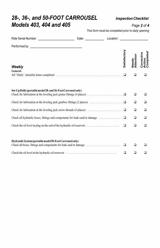
������������� ��������������� ����������� �����
�������� ���� ����� � ����������������������� �������������������������������
������������ �����������������������������������������������������������������������������������
������ �����������������������������������������
������������������������� ��������� �������� � ��������������������������������������������������������������������������������������������������� � �
���� ����� �������� ����� �� ��� ����� ��������� ������� ������������������������ �� � ������������ �� ����������� ����� �!������������������������������������������������������ � �
�� ������������������������ �� � ����������� ����"�����������#����� �!��������������������������������������������������� � �
�� ������������������������ �� � ������������� $���� ����� ����� �!������������������������������������������������������ � �
�� ������������������� �%�������������������� ��������� �������&�������� ������������������������������������� � � �
�� ����� ������ � ��������������� � �������� ��������������� � ��������������������������������������������������������� � � �
�������� ����� �������� ����� !"��� ��������� ������� ���������� �%�������������������� ��������� �������&�������� ����������������������������������������������������� � � �
�� ����� ������ � ������� ��������������� � ��������������������������������������������������������������������������������������� � � �
���������
�����
��� �����
������������
�����
��������
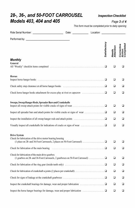
������������� ��������������� ����������� �����
�������� ���� ����� � ����������������������� �������������������������������
������������ �����������������������������������������������������������������������������������
������ �����������������������������������������
���������
�����
��� �����
������������
�����
��������
��� ��������������' ����� ��������� �������� � ������������������������������������������������������������������������������������������������ � �
������(��� ������� ����� �������������������������������������������������������������������������������������������������������������������������� � �
�� ������ ��������� ����� ������������ ����� ��������������������������������������������������������������������������������� � �
�� ������� ����� ��������������� ������� "� ������������� ����������� $����������������������������������������� � �
�#����$ �#��� ���%�� &���$ �������� '��� ��� ����(�)�*�(��� ��������$ �������������������������� ��������������������$ ��������������������������������������������������������� � �
(��� ���������� �� ����������������������������������� ���������������������$ �������������������������������������� � �
(��� ����� ����������������������$ ������ ������������������������������������������������������������������������������� � �
)����������� ���������������������������������������������������������$ ��������������������������������������������� � �
���+� ������� ������������������������ ����� �������� �������������
��*����� ����#+,�����-.,/����������� ��%�#����� �����01,/����������� �!����������������������������������������� � � �
�� ������������������������ ������� �������������������������������������������������������������������������������������������������� � �
�� ������������������������ ���������� �� ����"��*�� ����"����#+,�����-.,/����������� ��%�#�� ����" �����01,/����������� �!������������������������������ � � �
�� ������������������������ ������� ��������� �� ������!�������������������������������������������������������������������� � � �
�� ����������������������������������,��������#����� ��� ������������!�������������������������������������������������������� � �
�� ����������������� ���� ������ ������������� ����" ������������������������������������������������������������������������� � �
(��� ����� ������������� ���������������� %�$ ����������� ������������������������������������������������������� � � �
(��� ����� ����� ����� ��� ���������������� %�$ ����������� ��������������������������������������������������� � � �
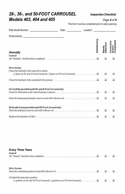
������������� ��������������� ����������� �����
�������� ���� ����� � ����������������������� �������������������������������
������������ �����������������������������������������������������������������������������������
������ �����������������������������������������
��������������������2�������� ��������� �������� � ������������������������������������������������������������������������������������������������������� � � �
���+� ������� ����� ��������������� ���������� �������
��*����� ����#+,�����-.,/����������� ��%�#����� �����01,/����������� �!������������������������������������������� � �
�� ����� ��������������� ���������������� ��������������������������������������������������������������������������������������������� � � �
���� ����� �������� ����� �� ��� ����� ��������� ������� ������������������������ �$� ��� �������� ����� �!��������������������������������������������������������������������������������� � � �
�������� ��������������������� � ����������� �����$����� $���������������������������������������������������������������������� � �
�������� ����� �������� ����� !"��� ��������� ������������� ����������� � ����������� �����$����� $����������������������������������������������������������������������������������������� � � �
3 ���� ��� ������������������ �������������������������������������������������������������������������������������������������������������������������� � � �
������� ������������������������������ ��������� �������� � ��������������������������������������������������������������������������������������������������������� � � �
���+� ������������� ������������� ����" ������� �����$����� $������������������������������������������������������������������������������������� � � �
4� �������� ���������� �� ����"��*�� ����"����#+,�����-.,/����������� ��%�#�� ����" �����01,/����������� �!������������������������������ � � �
���������
�����
��� �����
������������
�����
��������