1. refill behaviour in the heat transport system; 2. 3. Library/20054413.pdfSteam generated in the...
25
Thermalhydraulic Design Methods and Computer Codes by Xu Jijun*, V.S. Krishnan**, P.J. Ingham**, B.N. Hanna** and J.R. Buell** * Shanghai Jiaotong University ** Atomic Energy of Canada Limited Abstract Methods used for thermal and hydraulic design are typical of those available in the world, enhanced by major experimental programs. These programs are used to develop and confirm mathematical modeling. In particular, experiments are concentrated on modeling of CANDU- specific aspects of: 1. Thermalhydraulics, such as channel flows and pressure drop, critical heat flux, blowdown and refill behaviour in the heat transport system; 2. Flow and temperature distribution in the moderator system; and 3. Thermalhydraulics in the containment safety system. Both steady-state and transient conditions are included. This paper describes computer-modeling approaches used for design along with the experimental and theoretical verification programs which confirm the results. 1. HEAT TRANSPORT SYSTEM 1.1 Heat Transport System Description Figure 1 shows a simplified schematic of the CANDU heat transport system (HTS). The HTS circulates pressurized heavy water coolant through the fuel channels to remove the heat produced by fission in the nuclear fuel. The coolant transports the heat to steam generators, where it is transferred to light water to produce steam to drive the turbine. Two parallel HTS coolant loops are provided in CANDU 6. The heat from half of the several hundred fuel channels in the reactor core (380 in CANDU 6) is removed by each loop. Each loop has one inlet and one outlet header at each end of the reactor core. Heavy water is fed to each of the fuel channels through individual feeder pipes from the inlet headers and is returned from each channel through individual feeder pipes to the outlet headers. Each HTS loop is arranged in a ‘Figure of 8’, with the coolant making two passes, in opposite directions, through the core during each complete circuit, and the pumps in each loop operating in series. The coolant flow in adjacent channels is in opposite directions. The pressure in the HTS is controlled by a pressurizer connected to the outlet headers at one end of the reactor.
-
Upload
vuongtuyen -
Category
Documents
-
view
214 -
download
0
Transcript of 1. refill behaviour in the heat transport system; 2. 3. Library/20054413.pdfSteam generated in the...

Thermalhydraulic Design Methods and Computer Codes
byXu Jijun*, V.S. Krishnan**, P.J. Ingham**, B.N. Hanna** and J.R. Buell**
* Shanghai Jiaotong University** Atomic Energy of Canada Limited
AbstractMethods used for thermal and hydraulic design are typical of those available in the world,enhanced by major experimental programs. These programs are used to develop and confirmmathematical modeling. In particular, experiments are concentrated on modeling of CANDU-specific aspects of:
1. Thermalhydraulics, such as channel flows and pressure drop, critical heat flux, blowdown andrefill behaviour in the heat transport system;
2. Flow and temperature distribution in the moderator system; and3. Thermalhydraulics in the containment safety system.
Both steady-state and transient conditions are included.
This paper describes computer-modeling approaches used for design along with the experimentaland theoretical verification programs which confirm the results.
1. HEAT TRANSPORT SYSTEM
1.1 Heat Transport System Description
Figure 1 shows a simplified schematic of the CANDU heat transport system (HTS). The HTScirculates pressurized heavy water coolant through the fuel channels to remove the heat producedby fission in the nuclear fuel. The coolant transports the heat to steam generators, where it istransferred to light water to produce steam to drive the turbine. Two parallel HTS coolant loopsare provided in CANDU 6. The heat from half of the several hundred fuel channels in the reactorcore (380 in CANDU 6) is removed by each loop. Each loop has one inlet and one outlet headerat each end of the reactor core. Heavy water is fed to each of the fuel channels through individualfeeder pipes from the inlet headers and is returned from each channel through individual feederpipes to the outlet headers. Each HTS loop is arranged in a ‘Figure of 8’, with the coolantmaking two passes, in opposite directions, through the core during each complete circuit, and thepumps in each loop operating in series. The coolant flow in adjacent channels is in oppositedirections. The pressure in the HTS is controlled by a pressurizer connected to the outletheaders at one end of the reactor.
2
1.2 Heat Transport System Modeling
CATHENA, developed by AECL, has evolved with the objective of providing a high degree offlexibility in modeling thermalhydraulic systems. Although developed primarily for the analysisof CANDU nuclear reactors, the code has been successfully applied in the analysis and design ofexperimental test programs. CATHENA is also being used in support of the design, safety andlicensing of research reactors developed by. A comprehensive description of the code can befound in [1].
1.2.1 Thermalhydraulic Model
The CATHENA code uses a non-equilibrium, two-fluid thermalhydraulic model to describe fluidflow. Conservation equations for mass, momentum and energy are solved for each phase (liquidand vapour), resulting in a 6-equation model. Also, up to four noncondensible gases may berepresented as part of the vapour phase, yielding a 7- to 10-equation model. Interphase mass,momentum and energy transfer are flow-regime-dependent, and are calculated using constitutiverelationships obtained from the literature or are derived from single-effects experiments.
Noncondensable gas properties are available in CATHENA for H2, He, N2, Ar, CO2 and air. Thethermodynamic properties for the noncondensable gases are assumed to follow the ideal gas law.
The numerical solution technique used to solve the conservation equations is a one-step,staggered-mesh, semi-implicit, finite-difference method. The dependent variables defining thestate of a node or cell are pressure, void fraction, and phase enthalpies. If noncondensable gas(es)are present, the noncondensable fractions are also dependent variables. For connections betweennodes (called links), the dependent variables are the velocities of the gas and liquid phases.Conservation of mass is achieved using a truncation error correction technique.
A one-step finite-difference numerical solution scheme has been adopted that is not transit-time-limited. The resulting set of equations is not reduced to a pressure- or flow-field approach. Atime-step controller implemented in CATHENA automatically selects the next time step at eachfinite-difference time step. This is accomplished by monitoring changes in the dependentvariables, the selected derived variables, and the truncation error. If the maximum change is belowa prescribed value, the time step is increased; if the change is above a maximum prescribed value,it is decreased. The user may alter the default selection criteria through input data and thus checkthe temporal convergence of a given simulation.
1.2.2 Heat Transfer
Heat transfer from metal surfaces is handled by an extensive wall-heat-transfer package,GENHTP (GENeralized Heat Transfer Package). A set of flow-regime-dependent constitutiverelations specifies the energy transfer between the fluid and the pipe wall and/or the fuel element

3
surfaces. A variational finite-element method is used to model the heat transfer by conductionwithin the piping and fuel in the radial direction, and the heat transfer can also be modeled in thecircumferential direction. The radiative heat transfer and the zirconium/steam reaction rates canalso be calculated. The ability to calculate the heat transfer from individual groups of pins in afuel bundle subjected to stratified flow is built into this package. Under these conditions, the toppins in a bundle are exposed to vapour, while the bottom pins are exposed to liquid.
The GENHTP model also allows for the calculation of pressure tube (and calandria tube) strain,caused by pressure tube heat-up in a pressurized channel. Under certain postulated conditions,the pressure tube can “balloon” into contact with the calandria tube. When this occurs, heat willbe transferred from the channel, through the pressure tube and calandria tube to the D2Omoderator. CATHENA is able to model all these processes, including the contact conductancebetween the pressure tube and calandria tube.
CANDU fuel is usually modeled by a user-specified UO2 region, gap, and fuel sheath region.Temperature-dependent properties, available within GENHTP, are generally used for the UO2
and sheath. Although a constant gap conductance is usually used for LOCA analysis, a user-specified time dependent value may be applied.
1.2.3 Component Models
Component models that describe the behavior of pumps, valves, pressurizers, steam separators,and discharge through breaks are available to complete the idealizations of the reactor systems.
The Generalized Tank Model (GTM), a two-region, two-fluid, non-equilibrium thermalhydraulicmodel is provided to model tanks, allowing a variable cross-sectional area. The upper and lowertank regions are modeled as independent volumes which are allowed to exchange heat and massthrough mechanisms such as condensate fall, bubble rise or inter-region condensation.
1.2.4 Modeling Control Systems
Control systems may be modeled using a simulation-like language within CATHENA. Includedwithin this system is the ability to use FORTRAN-like statements. The majority of variablescalculated by CATHENA can be accessed, and used in these calculations. The results of thesecalculations can then be used to “control” models such as valve (opening fraction), reactorkinetics (reactivity insertion), etc.
In some cases, complex reactor control systems are already available in FORTRAN code. Forthese cases it is more efficient to use the existing control program, and “couple” it withCATHENA. CATHENA provides the required information to the Controller Program, and theController Program provides the required valve opening fractions, etc., to CATHENA.

4
1.3 Experimental Verification
The validation of CATHENA is supported by experimental data from a variety of CANDU-typical experimental facilities. The experiments cover a wide range of operating and postulatedaccident conditions. The major experimental programs are described below.
1.3.1 RD-14M
Figure 2 shows a simplified schematic of RD-14M, a multiple-heated channel, full- elevation,scaled, integral test facility, possessing most of the key components of a CANDU Primary HeatTransport System (PHTS). The facility is arranged in the standard CANDU two-pass figure-of-eight configuration. The facility is designed to produce similar fluid mass flux, transit time andpressure and enthalpy distributions as those typical of CANDU reactors under both forced andnatural circulation conditions [2].
The reactor core is simulated by ten, 6 m-long horizontal test sections. Each test section hassimulated end-fittings and seven electrical heaters, or fuel element simulators (FES), designed tohave many of the characteristics of a CANDU fuel bundle. Test sections are connected to headersvia full-length insulated feeders. Feeders are equipped with trace heating tapes to minimise heatlosses under natural circulation conditions. Pipework connecting outlet headers can also be valvedin to study the effect of outlet header interconnect geometry on mitigating oscillatory behaviourat full and low power conditions.
Above header piping is also CANDU-typical including two full-height, U-tube steam generatorsor boilers (BO1 and B02) and two bottom-suction centrifugal pumps (P1 and P2). Steamgenerated in the secondary, or shell, side of the steam generators is condensed in a jet condenser(CD1) and returned as feedwater to the boilers. For natural circulation experiments conductedpost 1990 a customised secondary system, designed to operate at reduced power levels typicallyencountered under natural circulation conditions, was utilised.
The primary-side pressure is controlled by a pressurizer/surge tank (TK1) using a 100-kWelectric heater (HR1). The facility operates at typical CANDU primary system pressures andtemperatures (typically 10 MPa(g) and 310°C at the outlet header).
For the natural circulation experiments, fluid removed from the primary circuit at header 7(HDR7) is cooled and stored in an inventory tank (TK3). Level monitoring of the inventory tankprovides a record of the quantity of primary fluid removed.
The RD-14M facility is extensively instrumented. FES sheath and centreline temperatures up to1000°C can be measured axially in five of the seven heaters in each simulated fuel channel toprovide a comprehensive picture of the FES temperature distribution. In addition flow,temperature, pressure and the void fraction of the fluid entering and leaving each test section is

5
measured. Gamma densitometers are used to measure the void fraction of fluid at the entrance andexit to both steam generators and at the discharge of both pumps. Fluid temperature, pressureand flow rates are measured at regular intervals throughout the facility. In addition, over 50differential pressure measurements provide an accurate picture of the pressure distributionthroughout the facility. Key secondary-side measurements such as pressure, steam flow rate andtemperature, feed water temperature and flow rate and internal shell-side recirculation rate arealso recorded. Overall, approximately 600 instruments are scanned and recorded using a dedicateddata acquisition system.
1.3.2 Header facilities
The core of a CANDU reactor consists of many fuel channels connected by feeder pipes tocommon inlet and outlet headers. Two-phase flow may occur in the headers during variouspostulated loss-of-coolant accidents (LOCA). Analysis of these postulated reactor accidentsrequires an understanding of the flow behaviour of the various reactor components, such as theheaders. CANDU Owners Group (COG) has two facilities to study the two-phase flowbehaviour in CANDU-like headers:
LArge-Scale Header (LASH) facility:
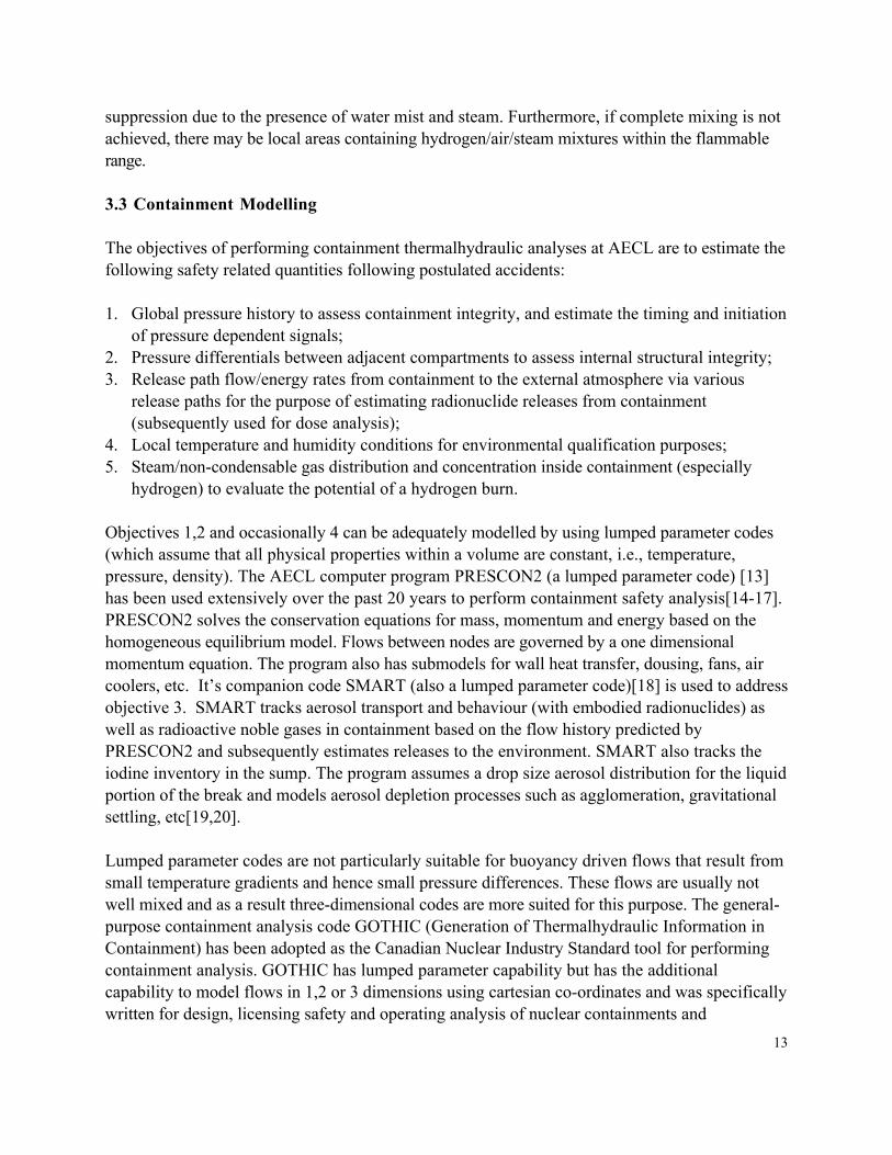
An overview of the LASH facility set-up is shown in Figure 3. The facility consists of twohorizontal headers (inlet and outlet) connected by six banks of five "U" shaped feeders, for a total ofthirty feeders [3]. Two basic types of tests can be performed in the LASH facility: two-phasesteady-state injection tests and blowdown/refills tests.
The test loop consists of a steam separator, a condenser, a fossil-fuel boiler, a preheater, aninventory tank, various boiler and liquid-water circulating pumps, a mixer, interconnecting pipingand valves, and a blowdown line. The test loop is designed to operate at a maximum pressure of 6MPa. For two-phase injection tests, boiler steam and liquid water are fed into the two-phase mixer,and the resulting two-phase mixture flows into the inlet header. The boiler is capable of supplying asuperheated-steam flow rate of approximately 4 kg/s at 7 MPa and 350∞C to the mixer. Liquidwater flow rates up to 80 kg/s can be supplied to the mixer. Discharge from the output header isreturned to the separator tank, where the liquid is recirculated through the liquid pump(s). Steamfrom the separator tank is returned to the condenser. The steam and liquid flows supplied to themixer are varied to provide a range of qualities and flow rates to the inlet header.
The inlet and outlet headers are CANDU typical in diameter, but are half-length intended to berepresentative of a half-length Pickering header. Each header is 4.1 m in length and 0.325 m indiameter (internal). Two vertical turrets, 0.308-m internal diameter, are attached to the top of eachheader. The turret locations are biased towards one end of the header. Each turret contains verticaland horizontal nozzle connections.
6
Thirty feeder lines, 49.2-mm inside diameter, extend vertically downwards from the inlet and outletheaders. The maximum vertical drop to the horizontal-feeder section is 10 m below the headercentreline, and the minimum vertical drop is 8.6 m below the header centreline. Each feeder consistsof a vertical inlet section and a vertical outlet section connected by a horizontal section.
The set-up for blowdown/refill experiments is similar to that for two-phase injection experiments,however, a blowdown line and a cold-water-injection line connects to both headers. The set-upshown in Figure 2 is for inlet and/or outlet header breaks. Other configurations of the blowdownpiping were used (for example, tests with feeder breaks), but are not shown here. Forblowdown/refill tests, the headers and feeders are preheated by injecting superheated steam into thetwo-phase mixer. After preheating, the headers are pressurised with superheated steam, and ablowdown is initiated by opening one or more of the blowdown line quick-acting valves. Cold wateris then injected into the inlet header, or both headers, to simulate the injection of emergency coolantliquid.
The LASH facility is extensively instrumented with over 500 channels. The phase distributions inthe headers are inferred using differential pressure and conductivity probes located axially along theheaders. Various fluid and surface-mount thermocouples are installed in the headers and feeders.Pressure cells are used to measure the header pressures, the header-to-header differential pressure,and various differential and absolute pressures in the feeders. All horizontal feeder sections containturbine flowmeters, and selected feeders are instrumented with gamma densitometers.
Transparent Header/Feeder facility: This facility has been running at AECL WhiteshellLaboratories since 1989. It consists of inlet and outlet headers, and thirty connecting feeders,with nearly identical internal dimensions to the LASH headers and feeders. However, the facilityis constructed of clear acrylic, which allows for the visual observation of flow. Two-phaseinjection experiments are performed by injecting an air-water mixture into the inlet header.Experiments are performed at near atmospheric pressure, liquid injection flow rates between 6and 60 kg/s, and air injection flow rates between 0 and approximately 24 litre/sec (standardconditions). This facility is mainly used to visual confirm behaviour inferred from experimentsperformed in the LASH facility. This facility is also used as a test bed for the development andtesting of new instrumentation.
1.3.3 Cold-Water Injection Test Facility
Figure 4 shows a simplified schematic of the Cold-Water Injection Test (CWIT) facility. Thisfacility is designed to study the thermalhydraulic behaviour of a CANDU fuel channel undervarious postulated accident conditions, such a emergency-coolant injection following a LOCA [4]. The facility contains all of the key components of a CANDU fuel-channel assembly, asdiscussed below.

7
The CWIT facility consists of a channel assembly, two headers, inlet and outlet feeders, twobreak-simulation devices, a blowdown tank, and a cold-water injection system. The full-scalechannel assembly consists of a 6-m long, electrically heated 37-element fuel bundle (FES). Thefuel bundle has an axially-cosine power distribution, and by applying different voltages to theindividual FES rings, a radial power depression ratio, representative of that in a CANDU reactoris maintained. The FES is housed in an actual CANDU pressure tube.
The pressure tube attaches to full-scale CANDU 6 end-fittings. Sections of vertical andhorizontal feeder pipe connect the end-fittings to the headers, and is representative of thearrangement in a CANDU reactor. Breaklines are attached to each header to facilitate thesimulation of a LOCA. Blowdowns are initiated by opening pneumatic quick-acting valuesinstalled on both blowdown lines. A cold-water injection system simulates the injection ofemergency coolant into the headers.
The test facility is extensively instrumented with nearly 250 data channels recorded.Thermocouples are used to measure fluid, pipe-wall, and FES heater surface temperatures.Differential and gauge pressure cells measure local pressure at various locations in the loop.Gamma densitometers are used to measure feeder void fractions.
1.3.4 End-Fitting Characterization Facility
The End-Fitting Characterization (EFC) facility was designed to investigate the thermalhydraulicand heat transfer behaviour of CANDU end-fittings when subjected to a wide range of two-phaseflow conditions. Tests were performed to study the flow resistance, the depressurization and theheat transfer behaviour of the end-fitting under postulated accident conditions.
The facility consisted of a CANDU 6 end-fitting, as shown in Figure 5 for heat-transfer tests. Thetest loop consisted of a steam generator, a condenser, a fossil fuel boiler, a preheater, a storage tank,various liquid-water pumps, a steam Venturi, interconnecting piping, and pressure and temperaturecontrol systems. The test loop was designed to operate at a maximum pressure of 5.0 MPa. Thefossil boiler was able to supply superheated steam at 7 MPa and 450oC and saturated water to thetest assembly via the steam/water mixer.
The end-fitting consisted of the end-fitting body, a liner tube, and a shield plug. The test assemblyconsisted of a feeder pipe, a simulated fuel channel, a water line, a steam/water mixer, return line tothe condenser, an end-fitting bypass line, interconnecting pipes, and various flanges that were usedto direct flow to various components of the end-fitting.
The simulated fuel channel consisted of a 2.0-m long pressure tube containing four copper pelleted37-Element bundles installed to simulate the entrance and exit effects of reactor fuel bundles. The

8
Zircaloy-4 pressure tube was rolled into the end-fitting, and extended inside the end-fitting by 112.6mm.
The instrumentations in the test assembly consists of single-beam gamma densitometers, water andsteam flow orifices, various thermocouples for temperature measurements, and capacitance typetransimitters for absolute pressure measurements. Inlet, outlet and return flows to the end-fittingand flow from the dead space are measured with turbine flowmeters. The instrumentations in thetest assembly varied from test to test.
The instrumentations in the end-fitting are clustered around six major axial planes. A total of 79thermocouples are installed along 5 radial plains at 6 axial locations. Multiple thermocouples at eachaxial plane and around the outside of the end-fitting components ensure that the temperaturedistribution that may arise due to flow stratification can be captured. Absolute and differentialpressure measurements are made using pressure cells. A 35-mm flowmeter is installed in each of thefour holes in the shield plug. Void-fraction measurements are made within the end-fitting assemblywith 18 single-beam gamma densitometers. Pitot tubes are used to measure the single-phasevelocities in the annulus and in the channel. Collapsed fluid level in the annulus, dead space, and inthe channel are inferred from differential pressure measurements.
2. MODERATOR SYSTEM
2.1 Moderator System Description
The prime operating purpose of the heavy water moderator in the calandria is to provide amedium to slow down high energy fission neutrons in the reactor to the appropriate thermalenergy level to promote further nuclear fission. In addition the moderator removes the heat that iscontinuously generated in the moderator as a result of heat production associated with neutronmoderation and gamma ray absorption processes, heat transfer from the pressure tubes across theannular gap to the calandria tubes, and heat transfer from reactor structures due to nuclear heatgeneration and temperature differences.
The heat is removed by circulating the moderator heavy water through an external circuit which isfully independent of the heat transport system. The moderator heavy water is extracted from thecalandria vessel through two outlet ports located at the bottom of the vessel. After dischargingthrough the outlet ports , the fluid mixes in a header and passes through one of two 100 percentpumps to be cooled via two parallel 100 percent tube and shell heat exchangers (where the heat isrejected to the Recirculated Cooling Water) and is returned to the moderator through inlet nozzleslocated at the side of the vessel. The MTC (Moderator Temperature Controller) maintains theoutlet temperature at a prescribed setpoint. The location of the inlet and outlet nozzles on thesides of the calandria ensures a uniform moderator temperature distribution inside the calandria.The operating pressure at the moderator free surface, which is maintained within a specified range
9
above the top row of channels, is slightly above atmospheric. The moderator head tank maintainsthe moderator level in the calandria within the required range by accommodating moderator swelland shrink resulting from temperature fluctuations. Figure 6 shows a schematic of the MainModerator System
2.2 Moderator function following a loss-of-coolant accident
The heavy water in the calandria functions as a heat sink in the unlikely event of a loss of coolantaccident with failure of emergency core cooling. The capability of this heat sink is assured bycontrolling the heavy water temperature in the calandria within specified limits.
Following a loss-of-coolant accident with loss of emergency core cooling there may be earlyPT/CT contacts due to high pressure in the PHTS and further PT/CT contacts due to pressuretube sag. The primary purpose of the moderator during a loss-of-coolant accident coincidentwith loss of emergency cooling with or without class IV power is to act as a heat sink followingPT/CT contact. In particular one of the factors that determines the nature of heat transfer at thesurface of the calandria tube in the event of PT/CT contacts is the degree of subcooling available(margin to boiling). The degree of local subcooling is the difference between the local saturationtemperature and the local moderator temperature. The degree of subcooling is an important factorin determining whether a critical heat flux “condition” exists at the surface of the calandria tube.It is also a major factor in determining post contact behavior, the latter being a function of thecirculation pattern within the moderator and hence the temperature distribution in the moderator.
Thus it is important to be able to predict local moderator temperatures, as the temperature of themoderator fluid surrounding a calandria tube has an important effect on the type of boiling whichoccurs following pressure tube/calandria tube contact. If film boiling takes place, the localmoderator temperature is also an important factor in determining the time required to rewet thecalandria tube and the amount of any possible post-contact deformation. The circulation patternand temperature distribution existing at the time of PT/CT contact will to a large degree dependon that existing during steady state operation.
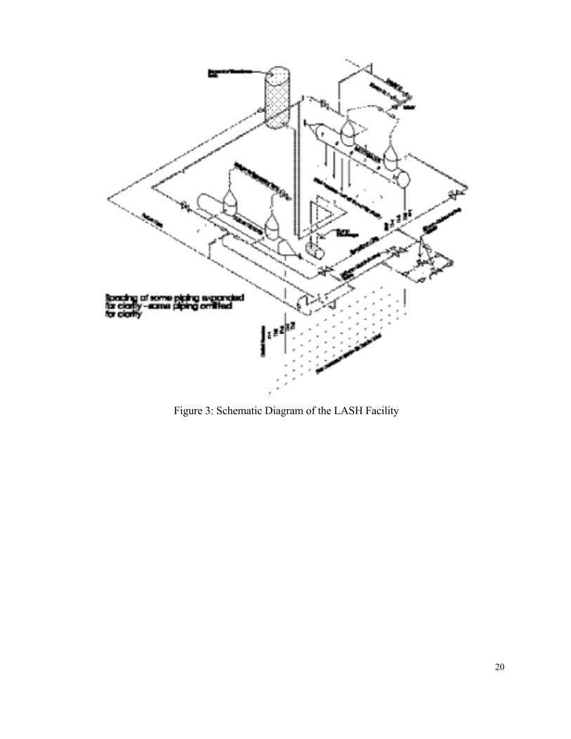
The circulation pattern and temperature distribution within the calandria vessel during full poweroperating conditions is dictated by the interaction between momentum and buoyancy forces.Momentum forces are generated by the incoming jets and buoyancy forces are generated fromheat addition within the core and reflector regions (causing density differences). Depending onthe relative magnitude of these forces, different flow patterns can exist within the moderatorvarying from momentum-dominated to buoyancy dominated. A momentum dominated flow canbe visualized as one in which the incoming jets penetrate to the top of the calandria, collide andare redirected downwards through the central core towards the outlet. A buoyancy-dominatedflow is one in which the jets do not penetrate to the top of the calandria but instead are redirectedin the reflector region towards the outlet. Figure 7 illustrates the two basic types of flow patterns

10
that could exist within the calandria. Various intermediate or mixed flow regimes are alsopossible.
2.3 Moderator Circulation Modelling
In order to predict local moderator temperatures during steady state operation or following aloss-of coolant accident with loss of emergency core cooling it is necessary to employ CFDcomputer codes due to complexity of the physical system/processes. The problem requiresadvanced numerical techniques as moderator circulation combines the effects of forced convectiondue to inlet jets and natural convection due to internal heat generation in the fluid, in a complexgeometry.
As part of the IST (Industry Standard Toolset) initiative, the computer programMODTURC_CLAS (MODerator TURbulent Circulation using Co-Located Advanced Solution)[5,6,7] has been adopted as the moderator circulation analysis tool within the Canadian NuclearIndustry. MODTURC_CLAS was derived from the CFD code TASC_flow by adding particularCANDU specific models to the code such as the heat exchangers, temperature controller, etc.
MODTURC_CLAS makes use of the most recent advances in computational methods to providegreater flexibility and economy in arriving at moderator temperature and flow predictions. It is astate-of-the art three–dimensional computational fluid dynamics computer code used to predictthe flow and temperature fields of a single–phase turbulent incompressible fluid, subject togeneral boundary conditions in a prescribed geometry. The numerical method used inMODTURC_CLAS is a fully implicit, co-located, finite volume method with a fluxelement–based domain discretization. This combines the well known geometric flexibility of thefinite-element method with the desirable conservation properties of the finite-volume method.
The governing partial differential equations for conservation of mass, Cartesian components ofmomentum, and energy form the basis of the governing equations in MODTURC_CLAS. Theprincipal solution variables are the Cartesian components of velocity, pressure, temperature, andturbulent kinetic energy and dissipation, with all other variables being functions of these. Thefully Cartesian co-ordinate system and co–located nodal arrangement for the solution variablesutilised by MODTURC_CLAS avoids the complexity of a general tensor or non–orthogonalstaggered grid formulation and, coupled with the numerically conservative finite volumeapproach, yields the desirable strong conservation properties.
2.4 Experimental Support-Code Validation
MODTURC_CLAS has undergone extensive validation[8] against small scale tests performed atSTERN Laboratories in Hamilton, Ontario, Canada. The small-scale test facility embodied all ofthe salient features of a typical CANDU 6 calandria, i.e., inlet jets, a tube–matrix (representativeof the CANDU core), and internal heat generation. Several experimental tests were performed at

11
STERN Labs including both isothermal and heat addition cases. Several distinct experiments wereconducted with the test apparatus. These include isothermal tests, a nominal-flowtest(approximating real calandria operating conditions) and a low flow test(corresponding to areduction in flow which generates a buoyancy dominated flow), and an enforced symmetrytest(performed by placing a divider in the vessel). Transient experiments were also carried out tosimulate postulated accident scenarios corresponding to those analyzed in CANDU safetyreports. Pickering B moderator temperature measurements (over a vertical line within themoderator) indicate that MODTURC_CLAS reasonably well. MODTURC_CLAS has also beenvalidated against in-core measurements taken in the Bruce A and Pickering B calandrias.
In addition to the current work, steady-state and LOCA/Loss of Class IV Power transientanalyses have been performed using MODTURC_CLAS for the CANDU 9 moderator system[9]. Other accident scenario results for the CANDU 9 moderator system (e.g., LOCA/LOECC)using MODTURC_CLAS has recently been analysed. Other analysis applications can be foundin [10,11,12]
More recently as part of the CANDU 9 validation effort a part scale three-dimensionalmoderator rig was constructed a Chalk River Laboratories. Validation exercises are now underway for MODTURC_CLAS simulation of the CANDU 9 configuration for both steady stateand transient analyses. Plans are also in progress to perform experiments relating to the CANDU6 configuration.
3. CONTAINMENT SAFETY SYSTEM
3.1 Containment System description
Under the most simplistic usage, the word “containment” implies the reactor building, which isalso referred to as the containment building. Under broader use the word signifies a combinationof systems, phenomena and processes which, when acting together, ensures that theenvironmental risk posed to the public is acceptable if radionuclides (radioactive materials)escape from the cooling system of the reactor. In general usage containment means a specialsafety system that is designed to seal or envelope (contain) coolant and radionuclide release fromthe reactor assembly. Containment encompasses all of the phenomena involving containment infuel, containment in the primary circuit and containment in water.
Containment in the reactor building considers the driving force for escape of radionuclides andcontainment processes. The driving force is a pressure difference across the containmentenvelope caused by steam/water discharges inside containment and/or by the continued operationof the ventilation system. This driving force is primarily responsible for the transport ofradionuclides within containment. Containment processes include radionuclide chemistry,
12
gravity forces (buoyancy, settling etc.), deposition and binding of radionuclides on surfaces andretention of radionuclides by filters and concrete pores, cracks, pools etc.
Containment design considers both the natural processes (physical and chemical aspects) and theeffect of the equipment inside containment, which is provided for either normal operation or tosupplement the containment design. Designed and engineered subsystems improve containmentperformance and provide in depth defense.
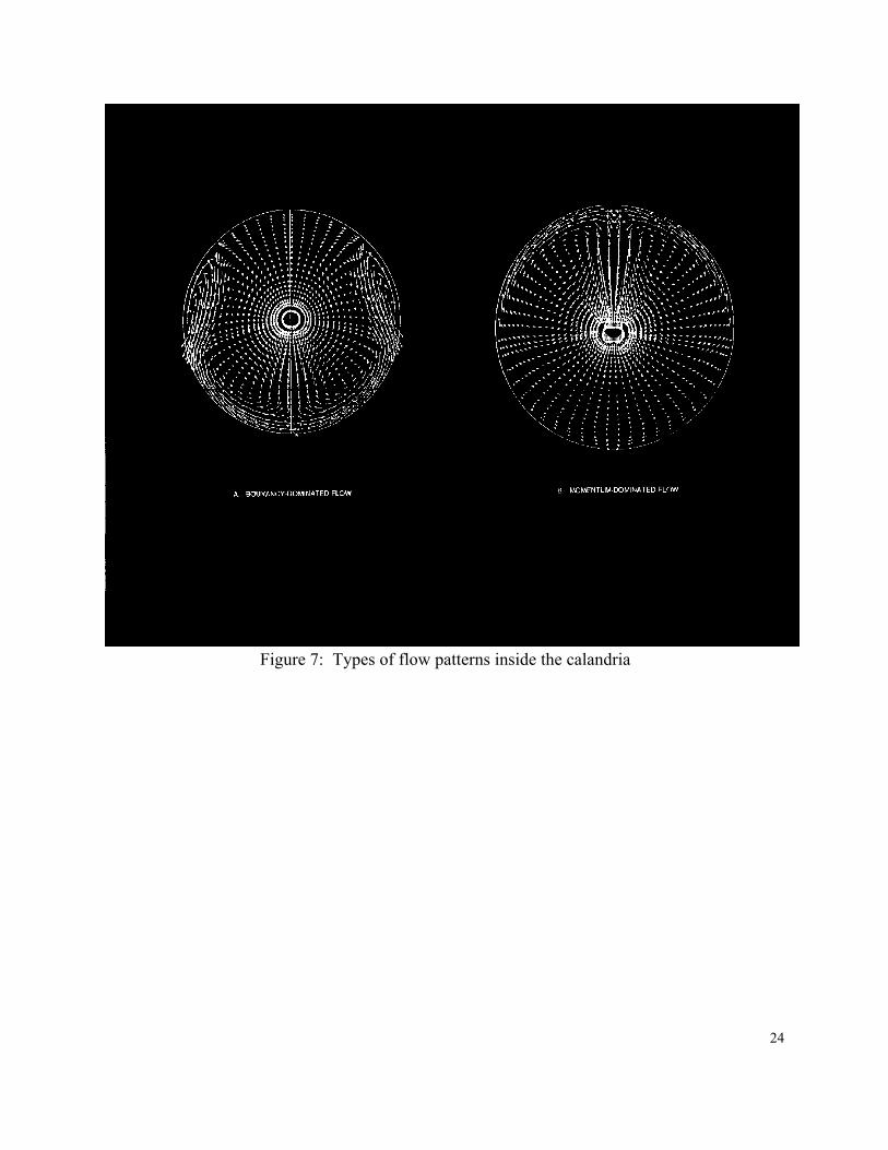
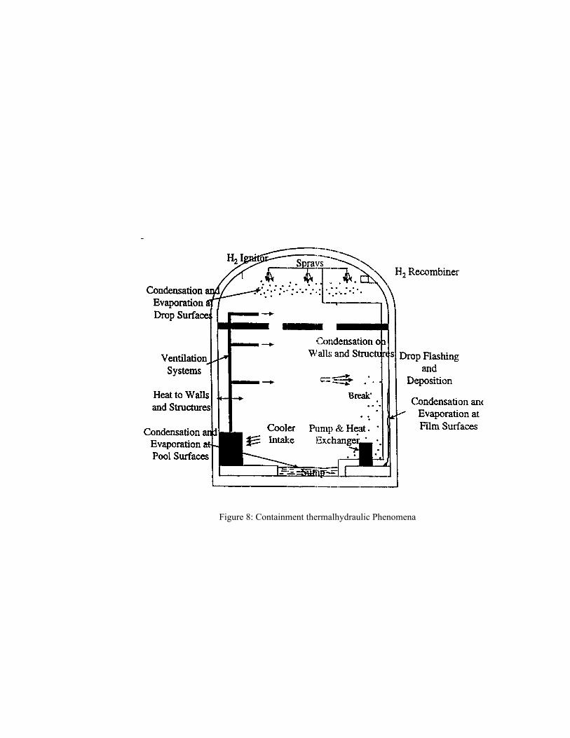
Engineered containment subsystems include the primary enclosure, the secondary enclosure, theisolation system, pressure relief systems (dousing), air coolers, heat exchangers, filter systems,gross leakage detection systems, etc. Of all these possible groups, CANDU 6 containment designincludes a leak tight reactor building which can withstand high pressures (with leakage much lessthan five percent by volume per day at a design pressure of 124kPa(g)), a very fast isolationsystem, a large dousing system for pressure suppression, local air coolers. Additional heat sinksmay include emergency core cooling and moderator system heat exchangers, and as an option andnot part of the design basis, an operator initiated post-accident containment depressurizationfacility. Figure 8 depicts the primary containment thermalhydraulic phenomena.
3.2 Safety Concerns
During normal operation, the containment system serves to control minor releases ofradionuclides from the reactor assembly but its primary purpose is to contain any radionuclidesthat may be released into containment if a breach occurs in the heat transport system boundary.Containment provides the final barrier to limit the release of radionuclides to the environment.
In addition to radionulides being released from the break and hence having the potential to bereleased to the external environment there also exist the concern of a hydrogen burn incontainment due to hydrogen release. This safety aspect is as important as possible radionucliderelease since a hydrogen burn deflagration/detonation could possible damage safety systems.
During certain postulated accidents, (LOCA+LOECC), hydrogen gas would invariably betransported from the fuel channel, where it is produced, to the containment atmosphere. Thehydrogen/steam mixture may be released either as a jet or a plume into the reactor vault or intothe feeder cabinet through a break in the heat transport system. Once hydrogen is released,various mixing mechanisms are available to promote dispersion within the accident vault and thecontainment building in general. These include natural convection, due to density differences andthermal gradients for inter room mixing, and forced convection from local air cooler fans formixing within the accident vault. Since the CANDU 6 containment is large, the uniformconcentration of hydrogen predicted to occur during these postulated accidents is near or belowthe flammability limit for hydrogen/steam/air mixtures. During the hydrogen transport andmixing period, the hydrogen concentration in the accident vault may exceed the flammability limitand undergo ignition if a sufficiently strong ignition source present to overcome flammability
13
suppression due to the presence of water mist and steam. Furthermore, if complete mixing is notachieved, there may be local areas containing hydrogen/air/steam mixtures within the flammablerange.
3.3 Containment Modelling
The objectives of performing containment thermalhydraulic analyses at AECL are to estimate thefollowing safety related quantities following postulated accidents:
1. Global pressure history to assess containment integrity, and estimate the timing and initiationof pressure dependent signals;
2. Pressure differentials between adjacent compartments to assess internal structural integrity;3. Release path flow/energy rates from containment to the external atmosphere via various
release paths for the purpose of estimating radionuclide releases from containment(subsequently used for dose analysis);
4. Local temperature and humidity conditions for environmental qualification purposes;5. Steam/non-condensable gas distribution and concentration inside containment (especially
hydrogen) to evaluate the potential of a hydrogen burn.
Objectives 1,2 and occasionally 4 can be adequately modelled by using lumped parameter codes(which assume that all physical properties within a volume are constant, i.e., temperature,pressure, density). The AECL computer program PRESCON2 (a lumped parameter code) [13]has been used extensively over the past 20 years to perform containment safety analysis[14-17].PRESCON2 solves the conservation equations for mass, momentum and energy based on thehomogeneous equilibrium model. Flows between nodes are governed by a one dimensionalmomentum equation. The program also has submodels for wall heat transfer, dousing, fans, aircoolers, etc. It’s companion code SMART (also a lumped parameter code)[18] is used to addressobjective 3. SMART tracks aerosol transport and behaviour (with embodied radionuclides) aswell as radioactive noble gases in containment based on the flow history predicted byPRESCON2 and subsequently estimates releases to the environment. SMART also tracks theiodine inventory in the sump. The program assumes a drop size aerosol distribution for the liquidportion of the break and models aerosol depletion processes such as agglomeration, gravitationalsettling, etc[19,20].
Lumped parameter codes are not particularly suitable for buoyancy driven flows that result fromsmall temperature gradients and hence small pressure differences. These flows are usually notwell mixed and as a result three-dimensional codes are more suited for this purpose. The general-purpose containment analysis code GOTHIC (Generation of Thermalhydraulic Information inContainment) has been adopted as the Canadian Nuclear Industry Standard tool for performingcontainment analysis. GOTHIC has lumped parameter capability but has the additionalcapability to model flows in 1,2 or 3 dimensions using cartesian co-ordinates and was specificallywritten for design, licensing safety and operating analysis of nuclear containments and

14
confinements, auxiliary buildings and related equipment, with applicability to a wide range ofother non-containment specific problems. GOTHIC solves mass, momentum and energybalances for three separate phases: vapor, continuous liquid (pool, films, etc) and dispersedliquid (drops). The vapor phase can be a mixture of steam and non-condensible gases and aseparate mass balance is maintained for each component of the vapor mixture.
The phase balance equations are coupled by mechanistic models and correlations for interfacemass, energy and momentum transfer that cover the entire flow regime from bubbly flow tofilm/drop flow as well as single phase flows. The interface models allow for the possibility ofthermal non-equilibrium among the phases and unequal phase velocities. GOTHIC includes fulltreatment of the momentum transport terms (in the Navier-Stokes equations) in multi-dimensional models together with he k-e turbulence model. Special models for engineered safetyequipment such as pumps, fans, valves, heat exchangers, coolers etc are also included.
In the near future GOTHIC may replace PRESCON2 following validation of its lumpedparameter capabilities as applied to CANDU 6 containment.
The primary use of the GOTHIC code at this time is however to determine hydrogen distributionin CANDU containment following a LOCA/LOECC event and the consequences of a hydrogenburn should it occur [21-25]. GOTHIC has the capability to model hydrogen deflagration in 3dimensions but not as yet detonation. GOTHIC has also been used for various CANDUapplications [26-27] including future passive design studies[28-29]
3.4 Experimental Support-Code Validation
PRESCON2 has an extensive validation base relating to pressure and pressure-differentialprediction within containment. It has been validated against some of the HDR hydrogen mixingexperiments with limited success[30,31]. A similar statement can be made concerning theGOTHIC code when used in lumped parameter mode. Many of the tests are for blow-downsimulations with basic lumped volume modeling. Both SMART and GOTHIC have recently beenadopted as the Canadian Nuclear Industry Tools for radionuclide behaviour and transport incontainment and hydrogen distribution/burn in containment respectively. As part of theIndustry Code Validation Plan both SMART and GOTHIC are undergoing validation atWhiteshell Laboratories for their intended application.
4. References
1. Hanna, B.N., 1998, CATHENA: A thermalhydraulic code for CANDU analysis, NuclearEngineering and Design (180) 113-131.
2. Ingham, P.J., et al, “Scaling Laws for Simulating the CANDU Heat Transport System, Proc.2nd Intern. Conf. Sim. Meth in Nucl. Engrg.,Montreal, Canada, 1986.

15
3. J.E. Kowalski and B.N. Hanna, “Studies of Two-Phase Flow Distribution in a CANDU-Type Header/Feeder System,” In Proceedings of the 4th International Topical Meeting onNuclear Reactor Thermal-hydraulics, Karlsruhe (FRG), October 10-13, Vol. 1, 28-33, 1989.
4. J.R. Buell and J.E. Kowalski, “Analysis of Refill Tests Conducted in the Modified Cold-Water Injection Test Facility,” Paper presented at the 1994 CNS annual conference, June 5-8,1994.
5. Huget, R.G., Szymanski, J.K., Galpin, P.F., Midvidy, W.I., “MODTURC_CLAS: AnEfficient Code for Analyses of Moderator Circulation in CANDU Reactors”, ThirdInternational Conference on Simulation Methods in Nuclear Engineering, Montreal, 1990April 18–20.
6. Wu,-X.; Szymanski,-J. “Spatial convergence of flow solutions obtained with MODTURC-CLAS”, Fourth international conference on simulation methods in nuclear engineering.Montreal, PQ (Canada). 2-4 Jun 1993.
7. Huget,-R.G.; Szymanski,-J.K.; Midvidy,-W.I. ”Status of physical and numerical modelling ofCANDU moderator circulation”. Tenth Annual Conference of the Canadian Nuclear Society.Ottawa, ON (Canada), 4-7 Jun 1989.
8. Wu, X., Mackinnon, J., and Szymanski, J., “Validation of MODTURC_CLAS - a CFD Codeused in Canadian Nuclear Safety Analysis”, CFD 97 - Fifth Annual Conference of theComputational Fluid Dynamics Society of Canada, May 25 - 27, 1997
9. W.M.Collins, B.Wu, “CANDU 9 Moderator Temperature Predictions for Steady State andAccident Scenarios Using MODTURC_CLAS” Fifth International Conference on SimulationMethods in Nuclear engineering. September 8-11, 1996. Montreal, Canada.
10. P.Y.C.Lee, W.M.Collins, “Moderator circulation Analysis for the Modified CANDU 6Design Using the CFD Code MODTURC_CLAS. Canadian Nuclear Society-NineteenthAnnual Conference Proceedings, Toronto, Ont 1998 Oct 18-21.
11. Mackinnon, J., and Szymanski, J., “Modeling of Coolant/Poison Mixing in the Calandria of aCANDU Nuclear Reactor using MODTURC_CLAS”, CFD 95, Banff Alberta, June 26-27,1995.
12. Wu,-X.; Ho,-D. Bruce NGS: “A discharge channel flow simulation using MODTURC-CLAS. Fifteenth Annual Conference of the Canadian Nuclear Society; 34th AnnualConference of the Canadian Nuclear Association, Montreal, PQ (Canada). 5-8 Jun 1994
13. Collins.W.M. “PRESCON2 sub-sonic compressible fluid flow modeling”, Internationalconference on containment design, Toronto, ON (Canada). 17-20 Jun 1984
14. M.S.Quraishi, R.A.Gibb, G.MacDonald, “PRESCON2 Predictions of Point LepreauContainment events”, Fifth International Conference on Simulation Methods in Nuclearengineering. September 8-11, 1996. Montreal, Canada.
15. R.Moffet, G.Sabourin, S.Cherradi, “PRESCON2 simulation of MACSTOR tests” Fifteenthannual conference of the Canadian Nuclear Society- 34th Annual Conference of the CanadianNuclear Association. Montreal, PQ. 5-8 Jun 1994.
16. T.H.Nguyen, W.M.Collins. “Simulations of hydrogen distribution experiments using thePRESCON2 and GOTHIC codes” Third International conference on containment design andoperation. Toronto, 19-21 Oct 1994

16
17. Min.T.K, Dick.J.E , “Recirculating emergency core coolant discharge modelling for long-termsingle unit containment analysis” , International conference on containment design. Toronto,ON (Canada), 17-20 Jun 1984.
18. Quraishi,-M.S. SMART: “A simple model for activity removal and transport”. 2.International conference on containment design and operation, Toronto, ON (Canada). 14-17Oct 1990.
19. Baek,-J.S.; Lee,-N.H.; Huh,-J.Y.; Choi,-J.H.; Hwang,-S.T.” Study on models for jet breakupfor CANDU 6 containment analysis”, 58th annual meeting of the American power conference.Chicago, IL (United States). 9-11 Apr 1996.
20. Baek,-J.S.; Huh,-J.Y.; Lee,-N.H.; Jeong,-J.H.; Choi,-J.H. “Study on models for mean diameterof aerosol particle for analysis of radionuclide behaviour inside containment”. Annals-of-Nuclear-Energy-Oxford. (1996), v. 23(13). p. 1079-1090.
21. Wang,-L.L.; Wong,-R.C. Overpressure in a CANDU containment due to hydrogendeflagration, (Ontario Hydro, Toronto (Canada)) ARS '97: American Nuclear Society (ANS)international meeting on advanced reactors safety. Orlando, FL (United States). 1-5 Jun 1997.
22. Lam,-K.K.; Wong,-R.C.; Fluke,-R.J. Modeling of hydrogen mixing in a set of complex andconnecting rooms in CANDU containment using GOTHIC. ARS '97: American NuclearSociety (ANS) international meeting on advanced reactors safety. Orlando, FL (UnitedStates). 1-5 Jun 1997.
23. Nguyen,-T.H.; Collins,-W.M. Hydrogen distribution analysis for CANDU 6 containmentusing the GOTHIC containment analysis code. 19. CNS simulation symposium. Hamilton,ON (Canada). 16-17 Oct 1995.
24. Krause,-M.; Whitehouse,-D.R.; Chan,-C.K.; Jones,-S.C.A Hydrogen distribution studiesrelevant to CANDU containments. : 19. CNS simulation symposium. Hamilton, ON(Canada). 16-17 Oct 1995.
25. Wang,-L.L.; Wong,-R.C. Modelling of hydrogen deflagration in a vented vessel. 19. CNSsimulation symposium. Hamilton, ON (Canada). 16-17 Oct 1995.
26. Um,-K.J. uce NGS A/B assessment of reactor vault fans on air mixing patterns. NuclearGenerating Station international conference on simulation methods in nuclear engineering.Montreal, PQ (Canada). 2-4 Jun 1993.
27. Rossitter,-G.; Wong,-R.C Modeling of containment as an alternate back-up heat sink in theevent of a total station blackout. 1995 National heat transfer conference. Portland, OR(United States). 5-9 Aug 1995.
28. Krause,-M.; Mathew,-P.M.; Spinks,-N.J.; Chin,-Y.S. Long-term passive CANDUcontainment response after a design-basis accident. ARS '97: American Nuclear Society(ANS) international meeting on advanced reactor safety. Orlando, FL (United States). 1-5 Jun1997.
29. Krause,-M.; Mathew,-P.M. Passive heat transport in advanced CANDU containment. 3.International conference on containment design and operation. Toronto, ON (Canada). 19-21Oct 1994.

17
30. Nguyen,-T.H.; Collins,-W.M. (Simulations of hydrogen distribution experiments using thePRESCON2 and GOTHIC codes. 3. International conference on containment design andoperation. Toronto, ON (Canada). 19-21 Oct 1994.
31. Wolf,-L.; Holzbauer,-H Hydrogen mixing experiments in the HDR-containment under severeaccident conditions. 21st water reactor safety information meeting. Bethesda, MD (UnitedStates). 25-27 Oct 1993.

18
Figure 1: Schematic diagram of the CANDU heat transport system

19
TS 10
TS 11
TS 12
TS 13
TS 14
TS 5
TS 6
TS 7
TS 8
TS 9
TESTSECTIONS
TK2EMERGENCY CORE
COOLANT TANK
CD1JET
CONDENSER
TK1SURGETANK
HX2
P7
P6
HR1
P8
P14
HX1
P11
P10
P1 P2
MV8
HD8HD7HD6 HD5
CD2DEGASSER B01
BOILERBO2
BOILER
HEADERINTERCONNECT
M
TK3INVENTORYTANK
Figure 2: Schematic Diagram of the RD-14M Integral CANDU Test Facility
20
Figure 3: Schematic Diagram of the LASH Facility

21
FIGURE 4: Schematic Diagram of the CWIT Facility

22
Figure 5: Diagram of the End-Fitting Characterization Facility

23
Figure 6: Diagram of the main moderator system
24
Figure 7: Types of flow patterns inside the calandria
25
Figure 8: Containment thermalhydraulic Phenomena