1 Prof. T.K. Anantha Kumar, E&E Dept., MSRIT DC Choppers.
140
1 Prof. T.K. Anantha Kumar, E&E Dept., MSRIT DC Choppers
-
Upload
robyn-ball -
Category
Documents
-
view
217 -
download
1
Transcript of 1 Prof. T.K. Anantha Kumar, E&E Dept., MSRIT DC Choppers.

1Prof. T.K. Anantha Kumar, E&E Dept., MSRIT
DC Choppers

2Prof. T.K. Anantha Kumar, E&E Dept., MSRIT
Introduction• Chopper is a static device.
• A variable dc voltage is obtained from a constant dc voltage source.
• Also known as dc-to-dc converter.
• Widely used for motor control.
• Also used in regenerative braking.
• Thyristor converter offers greater efficiency, faster response, lower maintenance, smaller size and smooth control.

3Prof. T.K. Anantha Kumar, E&E Dept., MSRIT
Choppers are of Two Types
Step-down choppers. Step-up choppers. In step down chopper output voltage is less
than input voltage. In step up chopper output voltage is more
than input voltage.

4Prof. T.K. Anantha Kumar, E&E Dept., MSRIT
Principle Of Step-down Chopper
V
i0
V 0
C hopper
R
+

5Prof. T.K. Anantha Kumar, E&E Dept., MSRIT
• A step-down chopper with resistive load.
• The thyristor in the circuit acts as a switch.
• When thyristor is ON, supply voltage appears across the load
• When thyristor is OFF, the voltage across the load will be zero.

6Prof. T.K. Anantha Kumar, E&E Dept., MSRIT
V d c
v 0
V
V /R
i0
Id c
t
t
tO N
T
tO F F

7Prof. T.K. Anantha Kumar, E&E Dept., MSRIT
verage value of output or load voltage.
verage value of output or load current.
Time interval for which SCR conducts.
Time interval for which SCR is OFF.
Period of switching
dc
dc
ON
OFF
ON OFF
V A
I A
t
t
T t t
or chopping period.
1 Freq. of chopper switching or chopping freq.f
T

8Prof. T.K. Anantha Kumar, E&E Dept., MSRIT
Average Output Voltage
.
duty cycle
ONdc
ON OFF
ONdc
ON
tV V
t t
tV V V d
T
tbut d
t

9Prof. T.K. Anantha Kumar, E&E Dept., MSRIT
2
0
Average Output Current
RMS value of output voltage
1 ON
dcdc
ONdc
t
O o
VI
RtV V
I dR T R
V v dtT

10Prof. T.K. Anantha Kumar, E&E Dept., MSRIT
2
0
2
But during ,
Therefore RMS output voltage
1
.
.
ON
ON o
t
O
ONO ON
O
t v V
V V dtT
tVV t V
T T
V d V

11Prof. T.K. Anantha Kumar, E&E Dept., MSRIT
2
2
Output power
But
Output power
O O O
OO
OO
O
P V I
VI
R
VP
R
dVP
R

12Prof. T.K. Anantha Kumar, E&E Dept., MSRIT
Effective input resistance of chopper
The output voltage can be varied by
varying the duty cycle.
idc
i
VR
I
RR
d

13Prof. T.K. Anantha Kumar, E&E Dept., MSRIT
Methods Of Control
• The output dc voltage can be varied by the following methods.
– Pulse width modulation control or constant frequency operation.
– Variable frequency control.

14Prof. T.K. Anantha Kumar, E&E Dept., MSRIT
Pulse Width Modulation
• tON is varied keeping chopping frequency ‘f’ & chopping period ‘T’ constant.
• Output voltage is varied by varying the ON time tON

15Prof. T.K. Anantha Kumar, E&E Dept., MSRIT
V 0
V
V
V 0
t
ttO N
tO N tO F F
tO F F
T

16Prof. T.K. Anantha Kumar, E&E Dept., MSRIT
Variable Frequency Control
• Chopping frequency ‘f’ is varied keeping either tON or tOFF constant.
• To obtain full output voltage range, frequency has to be varied over a wide range.
• This method produces harmonics in the output and for large tOFF load current may become discontinuous

17Prof. T.K. Anantha Kumar, E&E Dept., MSRIT
v 0
V
V
v 0
t
t
tO N
tO N
T
T
tO F F
tO F F

18Prof. T.K. Anantha Kumar, E&E Dept., MSRIT
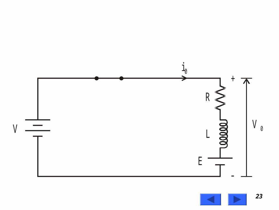
Step-down ChopperWith R-L Load
V
i0
V 0
C hopper
R
LFW D
E
+

19Prof. T.K. Anantha Kumar, E&E Dept., MSRIT
• When chopper is ON, supply is connected across load.
• Current flows from supply to load.
• When chopper is OFF, load current continues to flow in the same direction through FWD due to energy stored in inductor ‘L’.

20Prof. T.K. Anantha Kumar, E&E Dept., MSRIT
• Load current can be continuous or discontinuous depending on the values of ‘L’ and duty cycle ‘d’
• For a continuous current operation, load current varies between two limits Imax and Imin
• When current becomes equal to Imax the chopper is turned-off and it is turned-on when current reduces to Imin.

21Prof. T.K. Anantha Kumar, E&E Dept., MSRIT
O utpu tvo ltage
O utpu tcurrent
v 0
V
i0
Im a x
Im in
t
t
tO N
T
tO F F
C ontinuouscurrent
O utpu tcurrent
t
D iscon tinuouscurrent
i0

22Prof. T.K. Anantha Kumar, E&E Dept., MSRIT
Expressions For Load Current
iO For Continuous Current Operation When
Chopper Is ON (0 t tON)
23Prof. T.K. Anantha Kumar, E&E Dept., MSRIT
V
i0
V 0
R
L
E
+
-

24Prof. T.K. Anantha Kumar, E&E Dept., MSRIT
min
min
Taking Laplace Transform
. 0
At 0, initial current 0
OO
O O O
O
O
diV i R L E
dt
V ERI S L S I S i
S S
t i I
IV EI S
RR SLS SLL

25Prof. T.K. Anantha Kumar, E&E Dept., MSRIT
min
Taking Inverse Laplace Transform
1
This expression is valid for 0 ,
i.e., during the period chopper is ON.
At the instant the chopper is turned off,
load c
R Rt t
L LO
ON
V Ei t e I e
R
t t
maxurrent is O ONi t I

26Prof. T.K. Anantha Kumar, E&E Dept., MSRIT
When Chopper is OFF
i0
R
L
E

27Prof. T.K. Anantha Kumar, E&E Dept., MSRIT
max
When Chopper is OFF 0
0
Talking Laplace transform
0 0
Redefining time origin we have at 0,
initial current 0
OFF
OO
O O O
O
t t
diRi L E
dt
ERI S L SI S i
St
i I

28Prof. T.K. Anantha Kumar, E&E Dept., MSRIT
max
max
Taking Inverse Laplace Transform
1
O
R Rt t
L LO
I EI S
R RS LS SL L
Ei t I e e
R

29Prof. T.K. Anantha Kumar, E&E Dept., MSRIT
min
The expression is valid for 0 ,
i.e., during the period chopper is OFF
At the instant the chopper is turned ON or at
the end of the off period, the load current is
OFF
O OFF
t t
i t I

30Prof. T.K. Anantha Kumar, E&E Dept., MSRIT
min
max
max
max min
min
From equation
1
At ,
To Find &
1
R Rt t
L LO
ON O
dRT dRT
L L
V Ei t e I e
R
t t dT i t I
V EI e I e
I I
R

31Prof. T.K. Anantha Kumar, E&E Dept., MSRIT
max
min
From equation
1
At ,
1
R Rt t
L LO
OFF ON O
OFF
Ei t I e e
R
t t T t i t I
t t d T

32Prof. T.K. Anantha Kumar, E&E Dept., MSRIT
1 1
min max
min
max min
max
1
Substituting for in equation
1
we get,
1
1
d RT d RT
L L
dRT dRT
L L
dRT
L
RT
L
EI I e e
R
I
V EI e I e
R
V e EI
R Re

33Prof. T.K. Anantha Kumar, E&E Dept., MSRIT
max
1 1
min max
min
max min
Substituting for in equation
1
we get,
1
1
is known as the steady state ripple.
d RT d RT
L L
dRT
L
RT
L
I
EI I e e
R
V e EI
R Re
I I

34Prof. T.K. Anantha Kumar, E&E Dept., MSRIT
max min
max min
Therefore peak-to-peak ripple current
Average output voltage
.
Average output current
2
dc
dc approx
I I I
V d V
I II

35Prof. T.K. Anantha Kumar, E&E Dept., MSRIT
min max
min
max minmin
Assuming load current varies linearly
from to instantaneous
load current is given by
. 0O ON
O
I I
I ti I for t t dT
dTI I
i I tdT

36Prof. T.K. Anantha Kumar, E&E Dept., MSRIT
20
0
2
max minmin
0
2min max min2 2max min
min
0
RMS value of load current
1
1
21
dT
O RMS
dT
O RMS
dT
O RMS
I i dtdT
I I tI I dt
dT dT
I I I tI II I t dt
dT dT dT
37Prof. T.K. Anantha Kumar, E&E Dept., MSRIT
12 2
max min2min min max min
20
0
2
max minmin
0
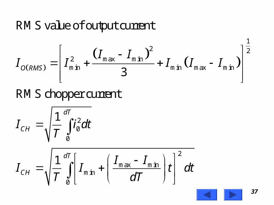
RMS value of output current
3
RMS chopper current
1
1
O RMS
dT
CH
dT
CH
I II I I I I
I i dtT
I II I t dt
T dT
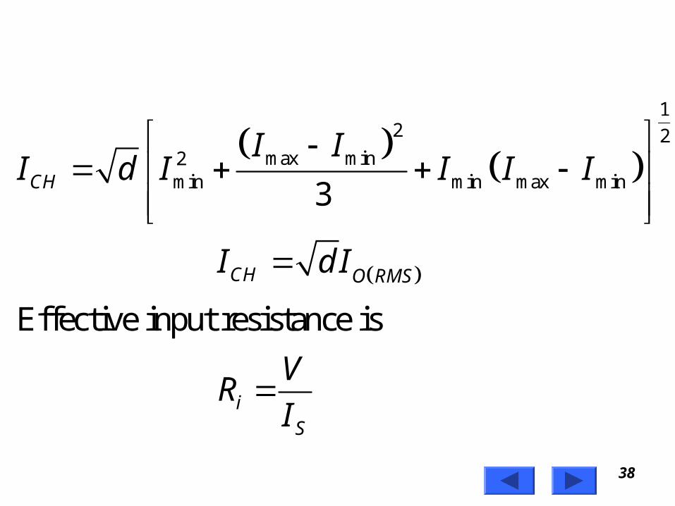
38Prof. T.K. Anantha Kumar, E&E Dept., MSRIT
12 2
max min2min min max min3
Effective input resistance is
CH
CH O RMS
iS
I II d I I I I
I d I
VR
I

39Prof. T.K. Anantha Kumar, E&E Dept., MSRIT
Where
Average source currentS
S dc
idc
I
I dI
VR
dI

40Prof. T.K. Anantha Kumar, E&E Dept., MSRIT
Principle Of Step-up Chopper
+
V OV
C hopper
CLOAD
DLI
+

41Prof. T.K. Anantha Kumar, E&E Dept., MSRIT
• Step-up chopper is used to obtain a load voltage higher than the input voltage V.
• The values of L and C are chosen depending upon the requirement of output voltage and current.
• When the chopper is ON, the inductor L is connected across the supply.
• The inductor current ‘I’ rises and the inductor stores energy during the ON time of the chopper, tON.

42Prof. T.K. Anantha Kumar, E&E Dept., MSRIT
• When the chopper is off, the inductor current I is forced to flow through the diode D and load for a period, tOFF.
• The current tends to decrease resulting in reversing the polarity of induced EMF in L.
• Therefore voltage across load is given by
. ., O O
dIV V L i e V V
dt

43Prof. T.K. Anantha Kumar, E&E Dept., MSRIT
• A large capacitor ‘C’ connected across the load, will provide a continuous output voltage .
• Diode D prevents any current flow from capacitor to the source.
• Step up choppers are used for regenerative braking of dc motors.

44Prof. T.K. Anantha Kumar, E&E Dept., MSRIT
Expression For Output Voltage
Assume the average inductor current to be
during ON and OFF time of Chopper.
Voltage across inductor
Therefore energy stored in inductor
= . .
Where
When Chopper
period of chopper.
is ON
ON
ON
I
L V
V I t
t ON

45Prof. T.K. Anantha Kumar, E&E Dept., MSRIT
(energy is supplied by inductor to load)
Voltage across
Energy supplied by inductor
where period of Chopper.
Neg
When Chopper
lecting losses, energy stored in inductor
is OFF
O
O OFF
OFF
L V V
L V V It
t OFF
L
= energy supplied by inductor L

46Prof. T.K. Anantha Kumar, E&E Dept., MSRIT
Where
T = Chopping period or period
of switching.
ON O OFF
ON OFFO
OFF
OON
VIt V V It
V t tV
t
TV V
T t

47Prof. T.K. Anantha Kumar, E&E Dept., MSRIT
1
1
1
1
Where duty cyle
ON OFF
OON
O
ON
T t t
V Vt
T
V Vd
td
T

48Prof. T.K. Anantha Kumar, E&E Dept., MSRIT
For variation of duty cycle ' ' in the
range of 0 1 the output voltage
will vary in the range O
O
d
d V
V V

49Prof. T.K. Anantha Kumar, E&E Dept., MSRIT
Performance Parameters• The thyristor requires a certain minimum time to
turn ON and turn OFF.
• Duty cycle d can be varied only between a min. & max. value, limiting the min. and max. value of the output voltage.
• Ripple in the load current depends inversely on the chopping frequency, f.
• To reduce the load ripple current, frequency should be as high as possible.

50Prof. T.K. Anantha Kumar, E&E Dept., MSRIT
Problem
• A Chopper circuit is operating on TRC at a frequency of 2 kHz on a 460 V supply. If the load voltage is 350 volts, calculate the conduction period of the thyristor in each cycle.

51Prof. T.K. Anantha Kumar, E&E Dept., MSRIT
3
460 V, = 350 V, f = 2 kHz
1Chopping period
10.5 sec
2 10
Output voltage
dc
ONdc
V V
Tf
T m
tV V
T

52Prof. T.K. Anantha Kumar, E&E Dept., MSRIT
3
Conduction period of thyristor
0.5 10 350
4600.38 msec
dcON
ON
ON
T Vt
V
t
t
53Prof. T.K. Anantha Kumar, E&E Dept., MSRIT
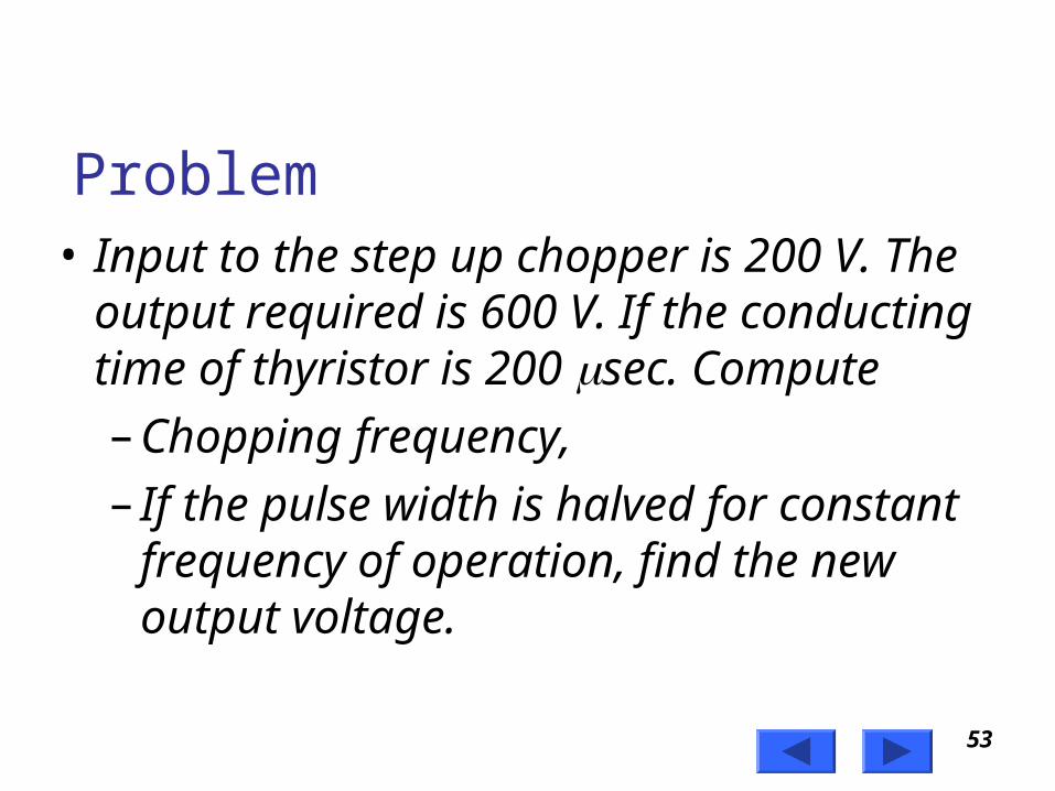
Problem• Input to the step up chopper is 200 V. The
output required is 600 V. If the conducting time of thyristor is 200 sec. Compute
– Chopping frequency,
– If the pulse width is halved for constant frequency of operation, find the new output voltage.

54Prof. T.K. Anantha Kumar, E&E Dept., MSRIT
6
200 , 200 , 600
600 200200 10
Solving for
300
ON dc
dcON
V V t s V V
TV V
T t
T
T
T
T s

55Prof. T.K. Anantha Kumar, E&E Dept., MSRIT
6
6
Chopping frequency
1
13.33
300 10Pulse width is halved
200 10100
2ON
fT
f KHz
t s

56Prof. T.K. Anantha Kumar, E&E Dept., MSRIT
6
6
Frequency is constant
3.33
1300
Output voltage =
300 10200 300 Volts
300 100 10
ON
f KHz
T sf
TV
T t

57Prof. T.K. Anantha Kumar, E&E Dept., MSRIT
Problem
• A dc chopper has a resistive load of 20 and input voltage VS = 220V. When chopper is ON, its voltage drop is 1.5 volts and chopping frequency is 10 kHz. If the duty cycle is 80%, determine the average output voltage and the chopper on time.

58Prof. T.K. Anantha Kumar, E&E Dept., MSRIT
220 , 20 , 10
0.80
= Voltage drop across chopper = 1.5 volts
Average output voltage
0.80 220 1.5 174.8 Volts
S
ON
ch
ONdc S ch
dc
V V R f kHz
td
TV
tV V V
T
V
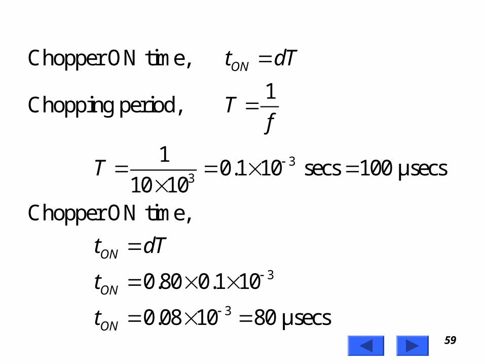
59Prof. T.K. Anantha Kumar, E&E Dept., MSRIT
33
3
3
Chopper ON time,
1Chopping period,
10.1 10 secs 100 μsecs
10 10Chopper ON time,
0.80 0.1 10
0.08 10 80 μsecs
ON
ON
ON
ON
t dT
Tf
T
t dT
t
t
60Prof. T.K. Anantha Kumar, E&E Dept., MSRIT
Problem
• In a dc chopper, the average load current is 30 Amps, chopping frequency is 250 Hz, supply voltage is 110 volts. Calculate the ON and OFF periods of the chopper if the load resistance is 2 ohms.

61Prof. T.K. Anantha Kumar, E&E Dept., MSRIT
3
30 , 250 , 110 , 2
1 1Chopping period, 4 10 4 msecs
250
&
30 20.545
110
dc
dcdc dc
dc
dc
I Amps f Hz V V R
Tf
VI V dV
RdV
IR
I Rd
V

62Prof. T.K. Anantha Kumar, E&E Dept., MSRIT
3
3 3
3
Chopper ON period,
0.545 4 10 2.18 msecs
Chopper OFF period,
4 10 2.18 10
1.82 10 1.82 msec
ON
OFF ON
OFF
OFF
t dT
t T t
t
t

63Prof. T.K. Anantha Kumar, E&E Dept., MSRIT
• A dc chopper in figure has a resistive load of R = 10 and input voltage of V = 200 V. When chopper is ON, its voltage drop is 2 V and the chopping frequency is 1 kHz. If the duty cycle is 60%, determine
– Average output voltage
– RMS value of output voltage
– Effective input resistance of chopper
– Chopper efficiency.

64Prof. T.K. Anantha Kumar, E&E Dept., MSRIT
V
i0
C hopper
+
R v 0
200 , 10 , 2
0.60, 1 .chV V R Chopper voltage drop V V
d f kHz

65Prof. T.K. Anantha Kumar, E&E Dept., MSRIT
Average output voltage
0.60 200 2 118.8 Volts
RMS value of output voltage
0.6 200 2 153.37 Volts
dc ch
dc
O ch
O
V d V V
V
V d V V
V

66Prof. T.K. Anantha Kumar, E&E Dept., MSRIT
220
0 0
Effective input resistance of chopper is
118.811.88 Amps
10200
16.8311.88
Output power is
1 1
iS dc
dcdc
iS dc
dT dTch
O
V VR
I I
VI
RV V
RI I
V VvP dt dt
T R T R

67Prof. T.K. Anantha Kumar, E&E Dept., MSRIT
2
2
0
0
0.6 200 22352.24 watts
10Input power,
1
1
chO
O
dT
i O
dTch
O
d V VP
R
P
P Vi dtT
V V VP dt
T R

68Prof. T.K. Anantha Kumar, E&E Dept., MSRIT
0.6 200 200 22376 watts
10Chopper efficiency,
100
2352.24100 99%
2376
chO
O
O
i
dV V VP
R
P
P
P

69Prof. T.K. Anantha Kumar, E&E Dept., MSRIT
Problem• A chopper is supplying an inductive load with a
free-wheeling diode. The load inductance is 5 H and resistance is 10.. The input voltage to the chopper is 200 volts and the chopper is operating at a frequency of 1000 Hz. If the ON/OFF time ratio is 2:3. Calculate – Maximum and minimum values of load current
in one cycle of chopper operation.– Average load current

70Prof. T.K. Anantha Kumar, E&E Dept., MSRIT
5 , 10 , 1000 ,
200 , : 2 : 3
Chopping period,
1 11 msecs
1000
2
3
2
3
ON OFF
ON
OFF
ON OFF
L H R f Hz
V V t t
Tf
t
t
t t

71Prof. T.K. Anantha Kumar, E&E Dept., MSRIT
3
2
35
33
53
1 10 0.6 msec5
ON OFF
OFF OFF
OFF
OFF
T t t
T t t
T t
t T
T

72Prof. T.K. Anantha Kumar, E&E Dept., MSRIT
3
3
3
max
1 0.6 10 0.4 msec
Duty cycle,
0.4 100.4
1 10Maximum value of load current is given by
1
1
ON OFF
ON
ON
dRT
L
RT
L
t T t
t
td
T
V e EI
R Re

73Prof. T.K. Anantha Kumar, E&E Dept., MSRIT
3
3
max
0.4 10 1 10
5
max 10 1 10
5
Since there is no voltage source in
the load circuit, E = 0
1
1
200 1
101
dRT
L
RT
L
V eI
Re
eI
e

74Prof. T.K. Anantha Kumar, E&E Dept., MSRIT
3
3
0.8 10
max 2 10
max
min
120
1
8.0047A
Minimum value of load current with E = 0
is given by
1
1
dRT
L
RT
L
eI
e
I
V eI
Re

75Prof. T.K. Anantha Kumar, E&E Dept., MSRIT
3
3
0.4 10 1 10
5
min 10 1 10
5
max min
200 17.995 A
101
Average load current
28.0047 7.995
8 A2
dc
dc
eI
e
I II
I
76Prof. T.K. Anantha Kumar, E&E Dept., MSRIT
Problem• A chopper feeding on RL load is shown in
figure, with V = 200 V, R = 5, L = 5 mH, f = 1 kHz, d = 0.5 and E = 0 V. Calculate – Maximum and minimum values of load
current.
– Average value of load current.
– RMS load current.
– Effective input resistance as seen by source.
– RMS chopper current.

77Prof. T.K. Anantha Kumar, E&E Dept., MSRIT
33
V = 200 V, R = 5 , L = 5 mH,
f = 1kHz, d = 0.5, E = 0
Chopping period is
1 11 10 secs
1 10T
f
i0
v 0
C hopper
R
LFW D
E
+

78Prof. T.K. Anantha Kumar, E&E Dept., MSRIT
3
3
3
3
max
0.5 5 1 10
5 10
max 5 1 10
5 10
0.5
max 1
Maximum value of load current is given by
1
1
200 10
51
140 24.9 A
1
dRT
L
RT
L
V e EI
R Re
eI
e
eI
e
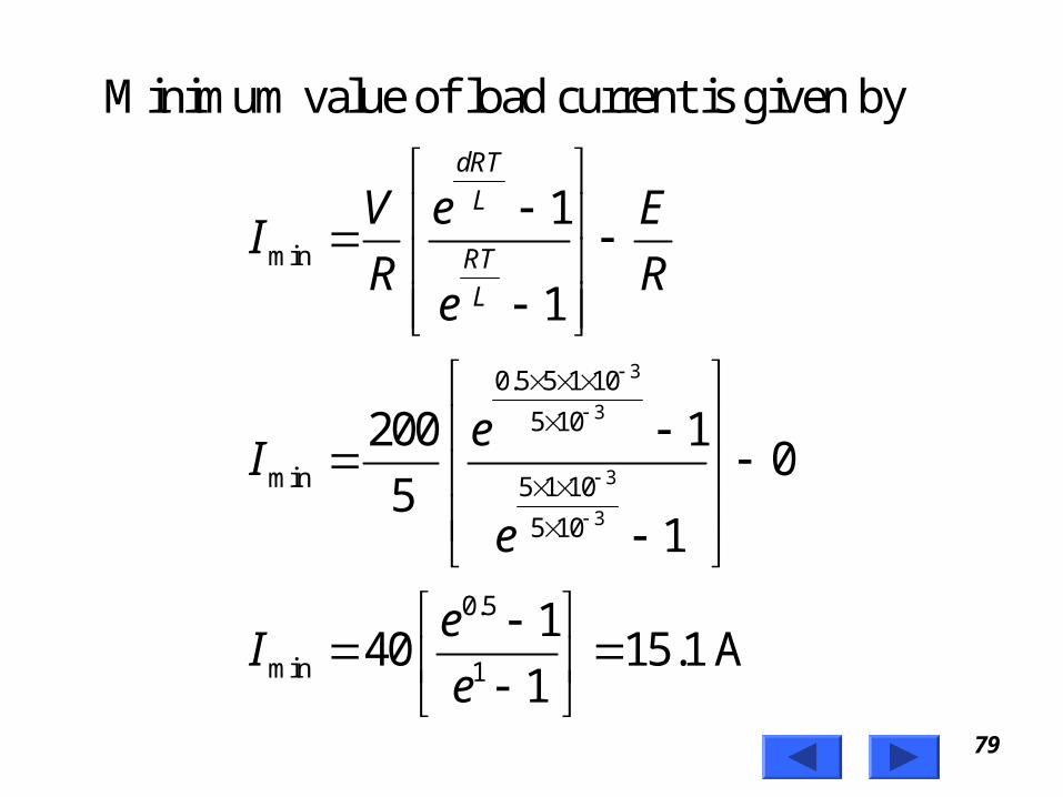
79Prof. T.K. Anantha Kumar, E&E Dept., MSRIT
3
3
3
3
min
0.5 5 1 10
5 10
min 5 1 10
5 10
0.5
min 1
Minimum value of load current is given by
1
1
200 10
51
140 15.1 A
1
dRT
L
RT
L
V e EI
R Re
eI
e
eI
e

80Prof. T.K. Anantha Kumar, E&E Dept., MSRIT
1 2
12 2
max min2min min max min
Average value of load current is
2for linear variation of currents
24.9 15.120 A
2RMS load current is given by
3
dc
dc
O RMS
I II
I
I II I I I I
81Prof. T.K. Anantha Kumar, E&E Dept., MSRIT
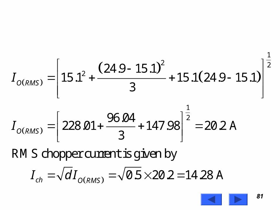
12 2
2
1
2
24.9 15.115.1 15.1 24.9 15.1
3
96.04228.01 147.98 20.2 A
3
RMS chopper current is given by
0.5 20.2 14.28 A
O RMS
O RMS
ch O RMS
I
I
I d I

82Prof. T.K. Anantha Kumar, E&E Dept., MSRIT
Effective input resistance is
= Average source current
0.5 20 10 A
Therefore effective input resistance is
20020
10
iS
S
S dc
S
iS
VR
I
I
I dI
I
VR
I

83Prof. T.K. Anantha Kumar, E&E Dept., MSRIT
Classification Of Choppers
• Choppers are classified as – Class A Chopper– Class B Chopper– Class C Chopper– Class D Chopper– Class E Chopper

84Prof. T.K. Anantha Kumar, E&E Dept., MSRIT
Class A Chopper
V
C hopper
FW D
+
v 0
v 0
i0
i0
LOAD
V

85Prof. T.K. Anantha Kumar, E&E Dept., MSRIT
• When chopper is ON, supply voltage V is connected across the load.
• When chopper is OFF, vO = 0 and the load current continues to flow in the same direction through the FWD.
• The average values of output voltage and current are always positive.
• Class A Chopper is a first quadrant chopper .

86Prof. T.K. Anantha Kumar, E&E Dept., MSRIT
• Class A Chopper is a step-down chopper in which power always flows form source to load.
• It is used to control the speed of dc motor.
• The output current equations obtained in step down chopper with R-L load can be used to study the performance of Class A Chopper.

87Prof. T.K. Anantha Kumar, E&E Dept., MSRIT
O utpu t cu rren t
Thyristo rgate pu lse
O utpu t vo ltage
ig
i0
v 0
t
t
ttO N
T
C H O N
FW D C onduc ts

88Prof. T.K. Anantha Kumar, E&E Dept., MSRIT
Class B Chopper
V
C hopper
+
v 0
v 0
i0
i0
L
E
R
D

89Prof. T.K. Anantha Kumar, E&E Dept., MSRIT
• When chopper is ON, E drives a current through L and R in a direction opposite to that shown in figure.
• During the ON period of the chopper, the inductance L stores energy.
• When Chopper is OFF, diode D conducts, and part of the energy stored in inductor L is returned to the supply.

90Prof. T.K. Anantha Kumar, E&E Dept., MSRIT
• Average output voltage is positive.• Average output current is negative. • Therefore Class B Chopper operates in second
quadrant.• In this chopper, power flows from load to
source.• Class B Chopper is used for regenerative
braking of dc motor.• Class B Chopper is a step-up chopper.

91Prof. T.K. Anantha Kumar, E&E Dept., MSRIT
O utpu t cu rren t
D con d u cts C h o pp e r
con d u cts
Thyristo rgate pu lse
O utpu t vo ltage
ig
i0
v 0
t
t
t
Im in
Im ax
T
tO NtO F F

92Prof. T.K. Anantha Kumar, E&E Dept., MSRIT
Expression for Output Current

93Prof. T.K. Anantha Kumar, E&E Dept., MSRIT
min
For the initial condition i.e.,
During the interval diode 'D' conduc
at 0
The solution of the ab
ts
voltage equation
ove equation is obtained
along similar lines as in s
is given by
OO
O
LdiV Ri E
dt
i t I t
tep-down chopper
with R-L load
94Prof. T.K. Anantha Kumar, E&E Dept., MSRIT
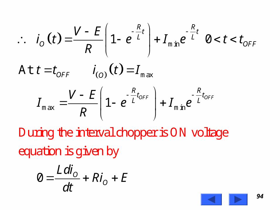
min
max
max min
During the interval chopper is ON voltage
equation is g
1 0
At
1
0
iven by
OFF OFF
R Rt t
L LO OFF
OFF O
R Rt t
L L
OO
V Ei t e I e t t
R
t t i t I
V EI e I e
R
LdiRi E
dt

95Prof. T.K. Anantha Kumar, E&E Dept., MSRIT
max
max
min
min max
Redefining the time origin, at 0
The solution for the stated initial condition is
1 0
At
1ON ON
O
R Rt t
L LO ON
ON O
R Rt t
L L
t i t I
Ei t I e e t t
R
t t i t I
EI I e e
R

96Prof. T.K. Anantha Kumar, E&E Dept., MSRIT
Class C Chopper
V
C hopper
+
v 0
D 1
D 2C H 2
C H 1
v 0i0
i0
L
E
R

97Prof. T.K. Anantha Kumar, E&E Dept., MSRIT
• Class C Chopper is a combination of Class A and Class B Choppers.
• For first quadrant operation, CH1 is ON or D2 conducts.
• For second quadrant operation, CH2 is ON or D1 conducts.
• When CH1 is ON, the load current is positive.• The output voltage is equal to ‘V’ & the load
receives power from the source. • When CH1 is turned OFF, energy stored in
inductance L forces current to flow through the diode D2 and the output voltage is zero.

98Prof. T.K. Anantha Kumar, E&E Dept., MSRIT
• Current continues to flow in positive direction.• When CH2 is triggered, the voltage E forces
current to flow in opposite direction through L and CH2 .
• The output voltage is zero.• On turning OFF CH2 , the energy stored in the
inductance drives current through diode D1 and the supply
• Output voltage is V, the input current becomes negative and power flows from load to source.

99Prof. T.K. Anantha Kumar, E&E Dept., MSRIT
• Average output voltage is positive• Average output current can take both positive
and negative values.• Choppers CH1 & CH2 should not be turned
ON simultaneously as it would result in short circuiting the supply.
• Class C Chopper can be used both for dc motor control and regenerative braking of dc motor.
• Class C Chopper can be used as a step-up or step-down chopper.

100Prof. T.K. Anantha Kumar, E&E Dept., MSRIT
G ate pu lseof C H 2
G ate pu lseof C H 1
O utput cu rren t
O utpu t vo ltage
ig 1
ig 2
i0
V 0
t
t
t
t
D 1 D 1D 2 D 2C H 1 C H 2 C H 1 C H 2
O N O N O N O N

101Prof. T.K. Anantha Kumar, E&E Dept., MSRIT
Class D Chopper
V+ v 0
D 2
D 1 C H 2
C H 1
v 0
i0
L ER i0

102Prof. T.K. Anantha Kumar, E&E Dept., MSRIT
• Class D is a two quadrant chopper.
• When both CH1 and CH2 are triggered simultaneously, the output voltage vO = V and output current flows through the load.
• When CH1 and CH2 are turned OFF, the load current continues to flow in the same direction through load, D1 and D2 , due to the energy stored in the inductor L.
• Output voltage vO = - V .

103Prof. T.K. Anantha Kumar, E&E Dept., MSRIT
• Average load voltage is positive if chopper ON time is more than the OFF time
• Average output voltage becomes negative if tON < tOFF .
• Hence the direction of load current is always positive but load voltage can be positive or negative.

104Prof. T.K. Anantha Kumar, E&E Dept., MSRIT
G ate pu lseof C H 2
G ate pu lseof C H 1
O utpu t curren t
O utpu t vo ltage
Average v 0
ig 1
ig 2
i0
v 0
V
t
t
t
t
C H ,C HO N1 2 D 1,D 2 Conducting

105Prof. T.K. Anantha Kumar, E&E Dept., MSRIT
G ate pu lseof C H 2
G ate pu lseof C H 1
O utpu t curren t
O utpu t vo ltage
Average v 0
ig 1
ig 2
i0
v 0
V
t
t
t
t
C HC H
1
2
D , D1 2

106Prof. T.K. Anantha Kumar, E&E Dept., MSRIT
Class E Chopper
V
v 0
i0L ER
C H 2 C H 4D 2 D 4
D 1 D 3C H 1 C H 3
+

107Prof. T.K. Anantha Kumar, E&E Dept., MSRIT
Four Quadrant Operationv 0
i0
C H - C H O NC H - D C onduc ts
1 4
4 2
D D2 3 - C onductsC H - D C onduc ts4 2
C H - C H O NC H - D C onduc ts
3 2
2 4
C H - D C onduc tsD - D C onducts
2 4
1 4

108Prof. T.K. Anantha Kumar, E&E Dept., MSRIT
• Class E is a four quadrant chopper
• When CH1 and CH4 are triggered, output current iO flows in positive direction through CH1 and CH4, and with output voltage vO = V.
• This gives the first quadrant operation.
• When both CH1 and CH4 are OFF, the energy stored in the inductor L drives iO through D2 and D3 in the same direction, but output voltage vO = -V.

109Prof. T.K. Anantha Kumar, E&E Dept., MSRIT
• Therefore the chopper operates in the fourth quadrant.
• When CH2 and CH3 are triggered, the load current iO flows in opposite direction & output voltage vO = -V.
• Since both iO and vO are negative, the chopper operates in third quadrant.

110Prof. T.K. Anantha Kumar, E&E Dept., MSRIT
• When both CH2 and CH3 are OFF, the load current iO continues to flow in the same direction D1 and D4 and the output voltage vO = V.
• Therefore the chopper operates in second quadrant as vO is positive but iO is negative.

111Prof. T.K. Anantha Kumar, E&E Dept., MSRIT
Effect Of Source &Load Inductance
• The source inductance should be as small as possible to limit the transient voltage.
• Also source inductance may cause commutation problem for the chopper.
• Usually an input filter is used to overcome the problem of source inductance.

112Prof. T.K. Anantha Kumar, E&E Dept., MSRIT
• The load ripple current is inversely proportional to load inductance and chopping frequency.
• Peak load current depends on load inductance.
• To limit the load ripple current, a smoothing inductor is connected in series with the load.

113Prof. T.K. Anantha Kumar, E&E Dept., MSRIT
Problem• For the first quadrant chopper shown in figure,
express the following variables as functions of V, R and duty cycle ‘d’ in case load is resistive.– Average output voltage and current– Output current at the instant of commutation– Average and RMS free wheeling diode current.– RMS value of output voltage– RMS and average thyristor currents.

114Prof. T.K. Anantha Kumar, E&E Dept., MSRIT
V
i0
v 0
C hopper
FW D
+
LOAD

115Prof. T.K. Anantha Kumar, E&E Dept., MSRIT
Average output voltage,
Average output current,
The thyristor is commutated at the instant
output current at the instant of commutation is
since V is the output v
ONdc
dcdc
ON
tV V dV
T
V dVI
R Rt t
V
R
oltage at that instant.
116Prof. T.K. Anantha Kumar, E&E Dept., MSRIT
20
0
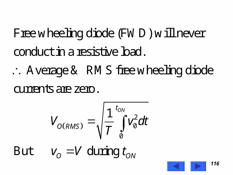
Free wheeling diode (FWD) will never
conduct in a resistive load.
Average & RMS free wheeling diode
currents are zero.
1
But during
ONt
O RMS
O ON
V v dtT
v V t

117Prof. T.K. Anantha Kumar, E&E Dept., MSRIT
2
0
2
1
Where duty cycle,
ONt
O RMS
ONO RMS
O RMS
ON
V V dtT
tV V
T
V dV
td
T

118Prof. T.K. Anantha Kumar, E&E Dept., MSRIT
RMS value of thyristor current
= RMS value of load current
Average value of thyristor current
= Average value of load current
O RMSV
R
dV
R
dV
R

119Prof. T.K. Anantha Kumar, E&E Dept., MSRIT
Impulse Commutated Chopper
• Impulse commutated choppers are widely used in high power circuits where load fluctuation is not large.
• This chopper is also known as
– Parallel capacitor turn-off chopper
– Voltage commutated chopper
– Classical chopper.

120Prof. T.K. Anantha Kumar, E&E Dept., MSRIT
LOAD
L
C
IL
L S
V S
+
_
+
_
T 2
T 1
D 1
a
biC
iT 1
v O
+
_
FW D

121Prof. T.K. Anantha Kumar, E&E Dept., MSRIT
• To start the circuit, capacitor ‘C’ is initially charged with polarity (with plate ‘a’ positive) by triggering the thyristor T2.
• Capacitor ‘C’ gets charged through VS, C, T2 and load.
• As the charging current decays to zero thyristor T2 will be turned-off.
• With capacitor charged with plate ‘a’ positive the circuit is ready for operation.
• Assume that the load current remains constant during the commutation process.

122Prof. T.K. Anantha Kumar, E&E Dept., MSRIT
• For convenience the chopper operation is divided into five modes.– Mode-1
– Mode-2
– Mode-3
– Mode-4
– Mode-5

123Prof. T.K. Anantha Kumar, E&E Dept., MSRIT
Mode-1 Operation
LOADL
C
IL
L S
V S
+
_
+
_
T 1
D 1
V C iC

124Prof. T.K. Anantha Kumar, E&E Dept., MSRIT
• Thyristor T1 is fired at t = 0.
• The supply voltage comes across the load.
• Load current IL flows through T1 and load.
• At the same time capacitor discharges through T1, D1, L1, & ‘C’ and the capacitor reverses its voltage.
• This reverse voltage on capacitor is held constant by diode D1.

125Prof. T.K. Anantha Kumar, E&E Dept., MSRIT
Capacitor Discharge Current
sin
1Where
& Capacitor Voltage
cos
C
C
Ci t V t
L
LC
V t V t

126Prof. T.K. Anantha Kumar, E&E Dept., MSRIT
Mode-2 Operation
LOAD
C
L S
V S+
_+
_
T 2
V C
IL
IL

127Prof. T.K. Anantha Kumar, E&E Dept., MSRIT
• Thyristor T2 is now fired to commutate thyristor T1.
• When T2 is ON capacitor voltage reverse biases T1 and turns if off.
• The capacitor discharges through the load from –V to 0.
• Discharge time is known as circuit turn-off time.

128Prof. T.K. Anantha Kumar, E&E Dept., MSRIT
C
Circuit turn-off time is given by
Where is load current.
t depends on load current, it must be designed
for the worst case condition which occur at the
maximum value of load current and mini
CC
L
L
V Ct
I
I
mum
value of capacitor voltage.

129Prof. T.K. Anantha Kumar, E&E Dept., MSRIT
• Capacitor recharges back to the supply voltage (with plate ‘a’ positive).
• This time is called the recharging time and is given by
• The total time required for the capacitor to discharge and recharge is called the commutation time and it is given by
Sd
L
V Ct
I
r C dt t t

130Prof. T.K. Anantha Kumar, E&E Dept., MSRIT
• At the end of Mode-2 capacitor has recharged to VS and the free wheeling diode starts conducting.

131Prof. T.K. Anantha Kumar, E&E Dept., MSRIT
Mode-3 Operation
LOAD
C
L S
V S
+_
+
_
T 2V S
FW D
IL
IL

132Prof. T.K. Anantha Kumar, E&E Dept., MSRIT
• FWD starts conducting and the load current decays.
• The energy stored in source inductance LS is transferred to capacitor.
• Hence capacitor charges to a voltage higher than supply voltage, T2 naturally turns off.

133Prof. T.K. Anantha Kumar, E&E Dept., MSRIT
The instantaneous capacitor voltage is
sin
Where
1
SC S L S
S
S
LV t V I t
C
L C

134Prof. T.K. Anantha Kumar, E&E Dept., MSRIT
Mode-4 Operation
LOAD
C
L S
V S
+_
+
_
D 1
LFW D
IL
V C

135Prof. T.K. Anantha Kumar, E&E Dept., MSRIT
• Capacitor has been overcharged i.e. its voltage is above supply voltage.
• Capacitor starts discharging in reverse direction.
• Hence capacitor current becomes negative. • The capacitor discharges through LS, VS, FWD,
D1 and L. • When this current reduces to zero D1 will stop
conducting and the capacitor voltage will be same as the supply voltage

136Prof. T.K. Anantha Kumar, E&E Dept., MSRIT
Mode-5 Operation
• Both thyristors are off and the load current flows through the FWD.
• This mode will end once thyristor T1 is fired.
LOAD
IL
FW D

137Prof. T.K. Anantha Kumar, E&E Dept., MSRIT
C a p a c i to r C u rr e n tI L
t
t
I p C u r r e n t t h r o u g h T 1
ic
0I p
iT1
0
I L

138Prof. T.K. Anantha Kumar, E&E Dept., MSRIT
t
t
t
Vo l ta g e a c r o s s T 1
O u tp u t Vo l t a g e
C a p a c i to r Vo l t a g e
tctd
v T1
V c
0v o
V s c+ V
V s
v c
V c
- V c

139Prof. T.K. Anantha Kumar, E&E Dept., MSRIT
Disadvantages• A starting circuit is required and the starting circuit
should be such that it triggers thyristor T2 first.
• Load voltage jumps to almost twice the supply voltage when the commutation is initiated.
• The discharging and charging time of commutation capacitor are dependent on the load current and this limits high frequency operation, especially at low load current.

140Prof. T.K. Anantha Kumar, E&E Dept., MSRIT
• Chopper cannot be tested without connecting load.
• Thyristor T1 has to carry load current as well as resonant current resulting in increasing its peak current rating.