1 Process Modeling Introduction The chapter will address the following questions: What is systems...
100
1 Process Modeling Introduction The chapter will address the following questions: What is systems modeling and what is the difference between logical and physical system models? What is process modeling and what are its benefits? What are the basic concepts and constructs of a process model. How do you read and interpret a data flow diagram. When in a project are process models constructed and where are they stored? How do you construct a context diagram to illustrate a system’s interfaces with its environment? How do you identify external and temporal business events for a system?
-
Upload
aubrey-jefferson -
Category
Documents
-
view
222 -
download
3
Transcript of 1 Process Modeling Introduction The chapter will address the following questions: What is systems...
1
Process Modeling
Introduction
The chapter will address the following questions: What is systems modeling and what is the difference between
logical and physical system models? What is process modeling and what are its benefits? What are the basic concepts and constructs of a process model. How do you read and interpret a data flow diagram. When in a project are process models constructed and where are
they stored? How do you construct a context diagram to illustrate a system’s
interfaces with its environment? How do you identify external and temporal business events for a
system?

2
Process Modeling
Introduction
The chapter will address the following questions: How do you perform event partitioning and organize events in a
functional decomposition diagram? How do you draw event diagrams and then merge those event
diagrams into a system diagram? How do you draw primitive data flow diagrams, and describe the
elementary data flows and processes in terms of data structures and procedural logic (Structured English and decision tables), respectively?

3
Process ModelingAn Introduction to System
Modeling
System Models System models play an important role in systems development. Systems analysts or users constantly deal with unstructured
problems. One way to structure such problems is to draw models.
A model is a representation of reality. Just as a picture is worth a thousand words, most system models are pictorial representations of reality.

4
Process ModelingAn Introduction to System
Modeling
System Models Models can be built for existing systems as a way to better
understand those systems, or for proposed systems as a way to document business requirements or technical designs.
Logical models show what a system ‘is’ or ‘does’. They are implementation-independent; that is, they depict the system independent of any technical implementation. As such, logical models illustrate the essence of the system. Popular synonyms include essential model, conceptual model, and business model.
Physical models show not only what a system ‘is’ or ‘does’, but also how the system is physically and technically implemented. They are implementation-dependent because they reflect technology choices, and the limitations of those technology choices. Synonyms include implementation model and technical model

5
Process ModelingAn Introduction to System
Modeling
System Models Systems analysts have long recognized the value of separating
business and technical concerns. They use logical system models to depict business
requirements. They use physical system models to depict technical designs.

6
Process ModelingAn Introduction to System
Modeling
System Models Systems analysis activities tend to focus on the logical system
models for the following reasons: Logical models remove biases that are the result of the way the
current system is implemented or the way that any one person thinks the system might be implemented.
Logical models reduce the risk of missing business requirements because we are too preoccupied with technical details.
Logical models allow us to communicate with end-users in non-technical or less technical languages.

7
Process ModelingAn Introduction to System
Modeling
System Models What is Process Modeling?
Process modeling is a technique for organizing and documenting the structure and flow of data through a system’s PROCESSES and/or the logic, policies, and procedures to be implemented by a system’s PROCESSES.
Process modeling originated in classical software engineering methods.
A systems analysis process model consists of data flow diagrams (DFDs).
• A data flow diagram (DFD) is a tool that depicts the flow of data through a system and the work or processing performed by that system. Synonyms include bubble chart, transformation graph, and process model.

8
Process ModelingINFORMATION SYSTEMS FRAMEWORK
SYSTEM
ANALYSTS
SYSTEMBUILDERS
(components)
SYSTEMDESIGNERS
(specification)
SYSTEMUSERS
(requirements)
SYSTEMOWNERS
(scope)
DatabaseTechnology
FOCUS ONSYSTEM
DATA
Business Processe
Data Flow Diagrams
Business Functions
Decomposition Diagram
FOCUS ONSYSTEM
PROCESSES
System Context
Context Diagram
FOCUS ON SYSTEM
INTERFACES
Software(and Hardware)
Technology
InterfaceTechnology Networking
Telchnology
FOCUS ONSYSTEM
GEOGRAPHY
Study Phase
(establish
system
improvement
objectives)
Definition Phase
(establish and
prioritize
business system
requirements)
Survey Phase
(establish scope
and project plan)
FASTMethodology
Marketing
Advertising
Orders
Sales
Cancellations Services
Order Management
SystemCustomer
Accounts Receivable Database
Warehouse
Bank
OrderPicking Order
Credit
Credit Voucher
Check credit
Validate customer
Validate products
Release order
Customers
Orders
Products
order
customer number
valid order
order without valid
customer
credit
order with valid products
approved order
quantity in stock
approved order
rejected order
prices
picking ticket
Reverse
Engineering
(optional)

9
Process Modeling
Reconcile Account Balances
Pay a
Bill
Withdraw Funds from an Account
Deposit Funds into an
Account
Bank
Creditor
Employer
Other Income Source
Bank
Monthly Account Statements
Account Transactions
Bank Accounts
Account Transactions
Bill
Payment
Monthly Statement
Account Balance
Transaction
Prior Monthly Statement
New or Modified Monthly Statement
Modified Balance
Pay
Reimbursement
Withdraw or transfer
Deposit
Payment
Modified Balance
Current Balance

10
Process ModelingAn Introduction to System
Modeling
System Models Data Flow Diagram
There are only three symbols and one connection:• The rounded rectangles represent processes or work to be done.
• The squares represent external agents – the boundary of the system.
• The open-ended boxes represent data stores, sometimes called files or databases, and correspond to all instances of a single entity in a data model.
• The arrows represent data flows, or inputs and outputs, to and from the processes.

11
Process ModelingAn Introduction to System
Modeling
System Models Data Flow Diagrams Versus Flowcharts
Processes on a data flow diagram can operate in parallel. Processes on flowcharts can only execute one at a time.
Data flow diagrams show the flow of data through the system. • Their arrows represent paths down which data can flow. Looping
and branching are not typically shown. Flowcharts show the sequence of processes or operations in an
algorithm or program.• Their arrows represent pointers to the next process or operation.
This may include looping and branching. Data flow diagrams can show processes that have dramatically
different timing and flowcharts don’t.

12
Process ModelingSystem Concepts for Process
Modeling
What is Systems Thinking? Systems thinking is the application of formal systems theory and
concepts to systems problem solving. Systems theory and concepts help us understand the way systems
are organized, and how they work. Techniques teach us how to apply the theory and concepts to build
useful real-world systems.

13
Process ModelingSystem Concepts for Process
Modeling
Process Concepts A System is a Process
The simplest process model of a system is based on inputs, outputs, and the system itself – viewed a process.
The process symbol defines the boundary of the system. The system is inside the boundary; the environment is outside
that boundary. The system exchanges inputs and outputs with its environment.

14
Process Modeling
The System's Environment (constantly changing)
The System Process
input output
Feeback and Control Loop
inputinput
outputoutput

15
Process ModelingSystem Concepts for Process
Modeling
Process Concepts A System is a Process (continued)
A rounded rectangle (the Gane and Sarson notation) is used represent a process.
Other process modeling notations:• The Demarco/Yourdon notation uses a circle.
• The SSADM/IDEF0 notation uses a rectangle. What is a process?
• A process is work performed on, or in response to, incoming data flows or conditions. A synonym is transform.
Process name
Process name
(the Gane & Sarson shape; used throughout this book)
(the DeMarco & Yourdon shape)
Process name
(the SSADM & IDEF0 shape)

16
Process ModelingSystem Concepts for Process
Modeling
Process Concepts Process Decomposition
What do you do when a complex system is too difficult to fully understand when viewed as a whole (meaning, as a single process)?
• In systems analysis we separate a system into its component subsystems, which in turn are decomposed into smaller subsystems, until such a time as we have identified manageable subsets of the overall system.
• This technique is called decomposition.
– Decomposition is the act of breaking a system into its component subsystems, processes, and subprocesses. Each ‘level’ of abstraction reveals more or less detail (as desired) about the overall system or a subset of that system.

17
Process Modeling0
The System
1 A Function of the System
1.1 Activity of the Function
Task 1.1.3
1.2 Another Activity of the Function
Task 1.1.1 Task 1.1.2
Task 1.2.2
Task 1.2.1
2 Another Function of the System
2.1 Activity of this Function
Task 2.1.1
Task 2.1.3 Task 2.1.4
Task 2.1.2
2.2 Another Activity of this Function
Task 2.2.1
Task 2.2.3
Task 2.2.2

18
Process ModelingSystem Concepts for Process
Modeling
Process Concepts Process Decomposition (continued)
A decomposition diagram is a popular tool to illustrate system decomposition.
• A decomposition diagram, also called a hierarchy chart, shows the top down functional decomposition and structure of a system.
A decomposition diagram is essentially a planning tool for more detailed processes models, namely, data flow diagrams.

19
Process ModelingSystem Concepts for Process
Modeling
Process Concepts Process Decomposition (continued)
The decomposition diagram rules:• Each process in a decomposition diagram is either a parent
process, a child process (of a parent), or both.
• A parent must have two or more children – a single child does not make sense since that would not reveal any additional detail about the system.
• In most decomposition diagramming standards, a child may have only one parent.
• A child of one parent may, of course, be the parent of its own children.

20
Process Modeling0
The System
1 A Function
2 Another Function
1.1 Activity of the
Function
1.2 Another Activity of the Function
Task 1.2.2
Task 2.1.1Task 1.1.1
Task 1.1.2
Task 1.1.3
Task 1.2.1
2.2 Another Activity of this Function
2.1 Acivity of this
Function
Task 2.1.2
Task 2.1.3
Task 2.1.4
Task 2.2.1
Task 2.2.2
Task 2.2.3

21
Process ModelingSystem Concepts for Process
Modeling
Process Concepts Logical Processes and Conventions
Logical processes are work or actions that must be performed no matter how you implement the system.
Each logical process is (or will be) implemented as one or more physical processes that may include:
• work performed by people
• work performed by robots or machines
• work performed by computer software Naming conventions for logical processes depend on where the
process is in the decomposition diagram/data flow diagram and type of process depicted.

22
Process ModelingSystem Concepts for Process
Modeling
Process Concepts Logical Processes and Conventions (continued)
There are three types of logical processes: functions, events, and elementary processes.
• A function is a set of related and on-going activities of the business. A function has no start or end – it just continuously performs its work as needed.
– Each of these functions may consist of dozens, or hundreds of more discrete processes to do support specific activities and tasks.
– Functions serve to group the logically related activities and tasks.
– Functions are named with nouns that reflect the entire function.

23
Process ModelingSystem Concepts for Process
Modeling
Process Concepts Logical Processes and Conventions (continued)
There are three types of logical processes: functions, events, and elementary processes.
• An event is a logical unit of work that must be completed as a whole. An event is triggered by a discrete input, and is completed when the process has responded with appropriate outputs. Events are sometimes called transactions.
– Functions consist of processes that respond to events. – Each of these events has a trigger and response that can be
defined by its inputs and outputs.– System functions are ultimately decomposed into business events. – Each business event is represented by a single process that will
respond to that event.

24
Process ModelingSystem Concepts for Process
Modeling
Process Concepts Logical Processes and Conventions (continued)
There are three types of logical processes: functions, events, and elementary processes.
• A event process can be further decomposed into elementary processes that illustrate in detail how the system must respond to an event.
– Elementary processes are discrete, detailed activities or tasks required to complete the response to an event. In other words, they are the lowest level of detail depicted in a process model. A common synonym is primitive process.
– Elementary processes should be named with a strong action verb followed by an object clause that describes what the work is performed on (or for).

25
Process ModelingSystem Concepts for Process
Modeling
Process Concepts Logical Processes and Conventions (continued)
Logical process models omit any processes that do nothing more than move or route data, thus leaving the data unchanged.
You should be left only with logical processes that:• Perform computations (e.g., calculate grade point average)• Make decisions (determine availability of ordered products)• Sort, filter or otherwise summarize data (identify overdue invoices)• Organize data into useful information (e.g., generate a report or
answer a question)• Trigger other processes (e.g., turn on the furnace or instruct a robot)• Use stored data (create, read, update or delete a record)

26
Process ModelingSystem Concepts for Process
Modeling
Process Concepts Logical Processes and Conventions (continued)
Be careful to avoid three common mechanical errors with processes (as illustrated in the following slide):
• A black hole is when a process has inputs but no outputs. Data enters the process and then disappears.
• A miracle is when a process has outputs but no input.
• A gray hole is when the inputs of a process are insufficient to produce the output. (most common)

27
Process Modeling
3.1.2 Create a new
member account
3.1.1 Generate an
employee bank statement
3.1.3 Freeze member account number
Accounts Receivable Department
Employee
Member Accounts Employees
Existing account
New account status
Employee status
Frozen account notification
Employee address
Bank statement
Membership application

28
Process ModelingSystem Concepts for Process
Modeling
Process Concepts Process Logic
Decomposition diagrams and data flow diagrams will prove very effective tools for identifying processes, but they are not good at showing the logic inside those processes.
We need to specify detailed instructions for the elementary processes on a data flow diagram.
To address this problem, we require a tool that marries some of the advantages of natural English with the rigor of programming logic tools.
• Structured English is a language and syntax, based upon the relative strengths of structured programming and natural English, for specifying the underlying logic of elementary processes on process models (such as data flow diagrams).

29
Process Modeling* Many of us do not write well, and we also tend not to question our writing abilities.
* Many of us are too educated! It’s often difficult for a highly educated person to communicate with anaudience that may not have had the same educational opportunities. For example, the average collegegraduate (including most analysts) has a working vocabulary of 10,000 to 20,000 words; on the otherhand, the average non-college graduate has a working vocabulary of around 5,000 words.
* Some of us write everything like it was a program. If business procedures required such precision,we’d write everything in a programming language.
* Too often, we allow the jargon and acronyms of computing to dominate our language.
* English statements frequently have an excessive or confusing scope. How would you carry out thisprocedure: “If customers walk in the door and they do not want to withdraw money from theiraccount or deposit money to their account or make a loan payment, send them to the trustdepartment.” Does this mean that the only time you should not send the customer to the trustdepartment is when he or she wishes to do all three of the transactions? Or does it mean that if acustomer does not wish to perform at least one of the three transactions, that customer should not besent to the trust department?
* We overuse compound sentences Consider the following procedure: “Remove the screws that holdthe outlet cover to the wall. Remove the outlet cover. Disconnect each wire from the plug, but firstmake sure the power to the outlet has been turned off.” An unwary person might try to disconnect thewires prior to turning off the power!
* Too many words have multiple definitions.
* Too many statements use imprecise adjectives. For example, an loan officer asks a teacher to certifythat a student is in good academic standing. What is good?
* Conditional instructions can be imprecise. For example, if we state that “all applicants under the ageof 19 must secure parental permission,” do we mean less than 19, or less than or equal to 19?
* Compound conditions tend to show up in natural English. For example, if credit approval is afunction of several conditions: credit rating, credit ceiling, annual dollar sales for the customer inquestion, then different combinations of these factors can result in different decisions. As the numberof conditions and possible combinations increases, the procedure becomes more and more tediousand difficult to write.

30
Process Modeling
1. For each CUSTOMER NUMBER in the data store CUSTOMERS:a. For each LOAN in the data store LOANS that matches the above CUSTOMER NUMBER:
1) Keep a running total of NUMBER OF LOANS for the CUSTOMER NUMBER.2) Keep a running total of ORIGINAL LOAN PRINCIPLE for the CUSTOMER NUMBER.3) Keep a running total of CURRENT LOAN BALANCE for the CUSTOMER NUMBER.4) Keep a running total of AMOUNTS PAST DUE for the CUSTOMER NUMBER.
b. If the TOTAL AMOUNTS PAST DUE for the customer number is greater than 100.00 then1) Write the customer number and data in the data flow LOANS AT RISK.
Else1) Exclude the customer number and data from the data flow LOANS AT RISK.

31
Process ModelingSystem Concepts for Process
Modeling
Process Concepts Process Logic (continued)
The overall structure of a Structured English specification is built using the fundamental constructs that have governed structured programming for nearly three decades.
These constructs are:• A sequence of simple, declarative sentences – one after another.
• A conditional or decision structure indicate that a process must perform different actions under well specified conditions.
• A iteration or repetition structure specifies that a set of actions should be repeated based on some stated condition. There are two variations on this construct.

32
Process ModelingSystem Concepts for Process
Modeling
Process Concepts Process Logic (continued)
The sequence construct:• Compound sentences are discouraged because they frequently
create ambiguity.
• Each sentence uses strong, action verbs such as GET, FIND, RECORD, CREATE, READ, UPDATE, DELETE, CALCULATE, WRITE, SORT, MERGE, or anything else recognizable or understandable to the users.
• A formula may be included as part of a sentence (e.g., CALCULATE GROSS PAY = HOURS WORKED X HOURLY WAGE.)

33
Process ModelingSystem Concepts for Process
Modeling
Process Concepts Process Logic (continued)
The conditional or decision structure construct:• There are two variations (and a departure) on this construct.
– The IF-THEN-ELSE construct specifies that one set of actions should be taken if a specified condition is ‘true’, but a different set of actions should be specified if the specified condition is false.
– The CASE construct is used when there are more than two sets of actions to choose from.
– For logic that based on multiple conditions and combinations of conditions, decision tables are a far more elegant logic modeling tool.

34
Process ModelingSystem Concepts for Process
Modeling
Process Concepts Process Logic (continued)
The iteration or repetition construct:• There are two variations on this construct.
– The DO-WHILE construct indicates that certain actions (usually expressed as one or more sequential and/or conditional statements) are repeated zero, one, or more times based on the value of the stated condition.
– The REPEAT-UNTIL constructs indicates that certain actions (again, usually expressed as one or more sequential and/or conditional statements) are repeated one or more times based on the value of the stated condition.

35
Process ModelingSystem Concepts for Process
Modeling
Process Concepts Process Logic (continued)
Structured English places the following restrictions on process logic:
• Only strong, imperative verbs may be used.
• Only names that have been defined in the project repository may be used.
• State formulas clearly using appropriate mathematical notations.
• Undefined adjectives and adverbs are not permitted unless clearly defined in the project repository as legal values for data attributes.
• Blocking and indentation are used to set off the beginning and ending of constructs and to enhance readability.
• When in doubt, user readability should always take precedence over programmer preferences.

36
Process ModelingC o n s t r u c t S a m p l e T e m p l a t e
S e q u e n c e o f a c t i o n s – u n c o n d i t i o n a l l y p e r f o r m as e q u e n c e o f a c t i o n s .
[ A c t i o n 1 ][ A c t i o n 2 ]…[ A c t i o n n ]
S i m p l e c o n d i t i o n a c t i o n s – i f t h e s p e c i f i e d c o n d i t i o ni s t r u e , t h e n p e r f o r m t h e f i r s t s e t o f a c t i o n s .O t h e r w i s e , p e r f o r m t h e s e c o n d s e t o f a c t i o n s .
U s e t h i s c o n s t r u c t i f t h e c o n d i t i o n h a s o n l y t w op o s s i b l e v a l u e s .
( N o t e : T h e s e c o n d s e t o f c o n d i t i o n s i s o p t i o n a l . )
I f [ t r u t h c o n d i t i o n ]t h e n
[ s e q u e n c e o f a c t i o n s o r o t h e r c o n d i t i o n a l a c t i o n s ]e l s e
[ s e q u e n c e o f a c t i o n s o r o t h e r c o n d i t i o n a l a c t i o n s ]E n d I f
C o m p l e x c o n d i t i o n a c t i o n s – t e s t t h e v a l u e o f t h ec o n d i t i o n a n d p e r f o r m t h e a p p r o p r i a t e s e t o f a c t i o n s .
U s e t h i s c o n s t r u c t i f t h e c o n d i t i o n h a s m o r e t h a n t w ov a l u e s .
D o t h e f o l l o w i n g b a s e d o n [ c o n d i t i o n ] :C a s e 1 : I f [ c o n d i t i o n ] = [ v a l u e ] t h e n
[ s e q u e n c e o f a c t i o n s o r o t h e r c o n d i t i o n a l a c t i o n s ]C a s e 2 : I f [ c o n d i t i o n ] = [ v a l u e ] t h e n
[ s e q u e n c e o f a c t i o n s o r o t h e r c o n d i t i o n a l a c t i o n s ]…C a s e n : I f [ c o n d i t i o n ] = [ v a l u e ] t h e n
[ s e q u e n c e o f a c t i o n s o r o t h e r c o n d i t i o n a l a c t i o n s ]E n d C a s e
M u l t i p l e c o n d i t i o n s – t e s t t h e v a l u e o f m u l t i p l ec o n d i t i o n s t o d e t e r m i n e t h e c o r r e c t s e t o f a c t i o n s .
U s e a d e c i s i o n t a b l e i n s t e a d o f n e s t e d i f - t h e n - e l s eS t r u c t u r e d E n g l i s h c o n s t r u c t s t o s i m p l i f y t h ep r e s e n t a t i o n o f c o m p l e x l o g i c t h a t i n v o l v e s
A d e c i s i o n t a b l e i s a t a b u l a r p r e s e n t a t i o n o f c o m p l e xl o g i c i n w h i c h r o w s r e p r e s e n t c o n d i t i o n s a n d p o s s i b l ea c t i o n s , a n d c o l u m n s i n d i c a t e w h i c h c o m b i n a t i o n s o fc o n d i t i o n s r e s u l t i n s p e c i f i c a c t i o n s .
D E C I S I O N T A B L E R u l e R u l e R u l e R u l e
[ C o n d i t i o n ] v a l u e v a l u e v a l u e v a l u e [ C o n d i t i o n ] v a l u e v a l u e v a l u e v a l u e [ C o n d i t i o n ] v a l u e v a l u e v a l u e v a l u e
[ S e q u e n c e o f a c t i o n s o r c o n d i t i o n a l a c t i o n s ]
X
[ S e q u e n c e o f a c t i o n s o r c o n d i t i o n a l a c t i o n s ]
X X
[ S e q u e n c e o f a c t i o n s o r c o n d i t i o n a l a c t i o n s ]
X
A l t h o u g h i t i s n ’ t a S t r u c t u r e d E n g l i s h c o n s t r u c t , a d e c i s i o n t a b l ec a n b e n a m e d , a n d r e f e r e n c e d w i t h i n a S t r u c t u r e d E n g l i s hp r o c e d u r e .
O n e - t o - m a n y i t e r a t i o n – R e p e a t t h e s e t o f a c t i o n su n t i l t h e c o n d i t i o n i s f a l s e .
U s e t h i s c o n s t r u c t i f t h e s e t o f a c t i o n s m u s t b ep e r f o r m e d a t l e a s t o n c e , r e g a r d l e s s o f t h e c o n d i t i o n ’ si n i t i a l v a l u e .
R e p e a t t h e f o l l o w i n g u n t i l [ t r u t h c o n d i t i o n ] :[ s e q u e n c e o f a c t i o n s o r c o n d i t i o n a l a c t i o n s ]
E n d R e p e a t
Z e r o - t o - m a n y i t e r a t i o n – R e p e a t t h e s e t o f a c t i o n su n t i l t h e c o n d i t i o n i s f a l s e .
U s e t h i s c o n s t r u c t i f t h e s e t o f a c t i o n s a r e c o n d i t i o n a lb a s e d o n t h e c o n d i t i o n ’ s i n i t i a l v a l u e .
D o W h i l e [ t r u t h c o n d i t i o n ] :[ s e q u e n c e o f a c t i o n s o r c o n d i t i o n a l a c t i o n s ]
E n d D o
- O R -
F o r [ t r u t h c o n d i t i o n ] :[ s e q u e n c e o f a c t i o n s o r c o n d i t i o n a l a c t i o n s ]
E n d F o r

37
Process ModelingSystem Concepts for Process
Modeling
Process Concepts Process Logic (continued)
Many processes are governed by complex combinations of conditions that are not easily expressed with Structured English.
This is most commonly encountered in business policies.• A policy is a set of rules that govern some process in the business.
In most firms, policies are the basis for decision making. Policies consist of rules that can often be translated into
computer programs if the users and systems analysts can accurately convey those rules to the computer programmer.
38
Process ModelingSystem Concepts for Process
Modeling
Process Concepts Process Logic (continued)
One way to formalize the specification of policies and other complex combinations of conditions is by using a decision table.
• A decision table is a tabular form of presentation that specifies a set of conditions and their corresponding actions.
A decision table consists of three components:• Condition stubs (the upper rows) describe the conditions or factors
that will affect the decision or policy.
• Action stubs (the lower rows) describe, in the form of statements, the possible policy actions or decisions.
• Rules (the columns) describe which actions are to be taken under a specific combination of conditions.

39
Process Modeling
A SIMPLE POLICY STATEMENT
CHECK CASHING IDENTIFICATION CARD
A customer with check cashing privileges is entitled to cashpersonal checks of up to $75.00 and payroll checks of fromcompanies pre-approved by LMART. This card is issued inaccordance with the terms and conditions of the application and issubject to change without notice. This card is the property ofLMART and shall be forfeited upon request of LMART.
SIGNATURE Charles C. Parker, Jr.EXPIRES May 31, 1998
THE EQUIVALENT POLICY DECISION TABLE
Conditions and Actions Rule 1 Rule 2 Rule 3 Rule 5
C1: Type of check personal payroll personal payrollC2: Check amount less than or equal to $75.00
yesdoesn’tmatter
nodoesn’tmatter
C3: Company accredited by LMART doesn’tmatter
yesdoesn’tmatter
no
A1: Cash the check X XA2: Don’t cash the check X X
40
Process ModelingSystem Concepts for Process
Modeling
Data Flows Data in Motion
A data flow is data in motion. The flow of data between a system and its environment, or
between two processes inside a system an relationship between a system and its environment, or between two processes is communication.
• A data flow represents an input of data to a process, or the output of data (or information) from a process. A data flow is also used to represent the creation, deletion, or update of data in a file or database (called a data store on the DFD).
• A data flow is depicted as a solid-line with arrow.

41
Process Modeling
Telephone Service Provider
Pay phone
bill
Itemized calls and
invoice
Itemized calls
Invoice
Correct use of the packet concept
Incorrect use of the
packet concept

42
Process ModelingSystem Concepts for Process
Modeling
Data Flows Data in Motion (continued)
A data flow is composed of either actual data attributes (also called data structures), or other data flows.
• A composite data flow is a data flow that consists of other data flows. They are used to combine similar data flows on general-level data flow diagrams to make those diagrams easier to read.

43
Process Modeling
(b) More Detailed DFD
(a) General-Level DFD
Process orderCustomer ...Order
Accepted Order
Process recurring
order
Process standard
order
Process rush order
Customer
Process employee
order
yOrder
Standing Order
Recurring Order
Rush Order
Employee Order
...
...
...
...Accepted Standing
Order
Accepted Recurring
Order
Accepted Rush Order
Accepted Employee
Order

44
Process ModelingSystem Concepts for Process
Modeling
Data Flows Data in Motion (continued)
Some data flow diagramming methods also recognize non-data flows called control flows.
• A control flow represents a condition or non-data event that triggers a process. Think of it as a condition to be monitored while the system works. When the system realizes that the condition meets some predetermined state, the process to which it is input is started.
• The control flow is depicted as a dashed-line with arrow.

45
Process ModelingSystem Concepts for Process
Modeling
Data Flows Logical Data Flows and Conventions
In the Analysis phase, we are only interested in logical data flows, that the flow is needed (not how we will implement that flow).
Data Flow Names:• Should discourage premature commitment to any possible
implementation.
• Should be descriptive nouns and noun phrases that are singular, as opposed to plural.
• Should be unique.
– Use adjectives and adverbs to help to describe how processing has changed a data flow.

46
Process Modeling
Orders
Process Order
Cencel Order
Change Order
Address
Summarize Unfilled Orders
OrderCancelled Order
Change of Address Summary of Orders
New Order
Address
Unfilled Order
l
New Order
Order to be
Deleted
2
1
2
2

47
Process ModelingSystem Concepts for Process
Modeling
Data Flows Logical Data Flows and Conventions (continued)
No data flow should ever go completely unnamed. Data flow names should describe the data flow without
describing how the flow is or could be implemented. All data flows must begin or end at a process, because data
flows are the inputs and outputs of a process.

48
Process Modeling
B1 B2 B1 B1
B1 B1
B1 B1
DS1 DS2 DS1
a process is needed to
exchange data flows between
boundaries
a process is needed to update (or use) a data
store
a process is needed to
present data from a data
store
a process is needed to move data
from one data store to another
DS2
DS1
DS1 DS1
DS1
Illegal data flows
Corrected data flows

49
Process ModelingSystem Concepts for Process
Modeling
Data Flows Data Flow Conservation
Data conservation, sometimes called “starving the processes”, requires that a data flow only contain that data which is truly needed by the receiving process.
By ensuring that processes only receive as much data as they really need, we simplify the interface between those processes.
In order to practice data conservation, we must precisely define the data composition of each (non-composite) data flow.
• Data composition is expressed in the form of data structures.

50
Process ModelingSystem Concepts for Process
Modeling
Data Flows Data Structures
A data flow contains data items called attributes.• A data attribute is the smallest piece of data that has meaning to the
end users and the business. • The data attributes that comprise a data flow are organized into data
structures.– Data structures are specific arrangements of data attributes that
define the organization of a single instance of a data flow. Data flows can be described in terms of the following types of
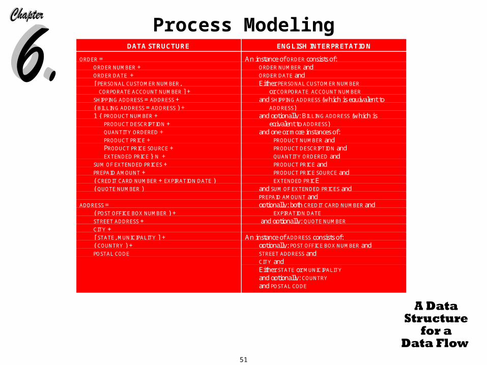
data structures:• A sequence or group of data attributes that occur one after another.• The selection of one or more attributes from a set of attributes.• The repetition of one or more attributes.
51
Process ModelingDATA STRUCTURE ENGLISH INTERPRETATION
ORDER =ORDER NUMBER +ORDER DATE +[ PERSONAL CUSTOMER NUMBER, CORPORATE ACCOUNT NUMBER ] +SHIPPING ADDRESS = ADDRESS +( BILLING ADDRESS = ADDRESS ) +1 { PRODUCT NUMBER +
PRODUCT DESCRIPTION +QUANTITY ORDERED +PRODUCT PRICE +PRODUCT PRICE SOURCE +EXTENDED PRICE } N +
SUM OF EXTENDED PRICES +PREPAID AMOUNT +( CREDIT CARD NUMBER + EXPIRATION DATE )( QUOTE NUMBER )
ADDRESS =( POST OFFICE BOX NUMBER ) +STREET ADDRESS +CITY +[ STATE, MUNICIPALITY ] +( COUNTRY ) +POSTAL CODE
An instance of ORDER consists of:ORDER NUMBER andORDER DATE andEither PERSONAL CUSTOMER NUMBER
or CORPORATE ACCOUNT NUMBER
and SHIPPING ADDRESS (which is equivalent to
ADDRESS) and optionally: BILLING ADDRESS (which is
eqivalent to ADDRESS)and one or more instances of:
PRODUCT NUMBER andPRODUCT DESCRIPTION andQUANTITY ORDERED andPRODUCT PRICE andPRODUCT PRICE SOURCE andEXTENDED PRICE
and SUM OF EXTENDED PRICES andPREPAID AMOUNT andoptionally: both CREDIT CARD NUMBER and
EXPIRATION DATE
and optionally: QUOTE NUMBER
An instance of ADDRESS consists of:optionally: POST OFFICE BOX NUMBER andSTREET ADDRESS andCITY andEither STATE or MUNICIPALITY
and optionally: COUNTRY
and POSTAL CODE
Figure 6.15

52
Process ModelingData Structure Format by Example
(relevant portion is boldfaced)
English Interpretation
(relevant portion is boldfaced)
Sequence of Attributes - The sequence datastructure indicates one or more attributes that may(or must) be included in a data flow.
WAGE AND TAX STATEMENT =TAXPAYER IDENTIFICATION NUMBER +TAXPAPYER NAME +TAXPAPYER ADDRESS +WAGES, TIPS, AND COMPENSATION +FEDERAL TAX WITHHELD + …
An instance of WAGE AND TAX STATEMENT consistsof:
TAXPAYER IDENTIFICATION NUMBER andTAXPAYER NAME andTAXPAYER ADDRESS andWAGES, TIPS, AND COMPENSATION andFEDERAL TAX WITHHELD and …
Selection of Attributes - The selection datastructure allows you to show situations wheredifferent sets of attributes describe differentinstances of the data flow.
ORDER =( PERSONAL CUSTOMER NUMBER, CORPORATE ACCOUNT NUMBER ) +ORDER DATE + …
An instance of ORDER consists of:Either PERSONAL CUSTOMER NUMBER or
CORPORATE ACCOUNT NUMBER; andORDER DATE and …
Repetition of Attributes - The repetition datastructure is used to set off a data attribute or groupof data attributes that may (or must) repeatthemselves a specified number of times for a singleinstance of the data flow.
The minimum number of repetitions is usually zeroor one.
The maximum number of repetitions may bespecified as “n” meaning “many” where the actualnumber of instances varies for each instance of thedata flow.
CLAIM =POLICY NUMBER +POLICYHOLDER NAME +POLICYHOLDER ADDRESS +0 { DEPENDENT NAME +
DEPENDENT’S RELATIONSHIP } N +1 { EXPENSE DESCRIPTION +
SERVICE PROVIDER +EXPENSE AMOUNT } N
An instance of CLAIM consists of:POLICY NUMBER andPOLICYHOLDER NAME andPOLICYHOLDER ADDRESS andzero or more instances of:
DEPENDENT NAME andDEPENDENT’S RELATIONSHIP and
one or more instances of:EXPENSE DESCRIPTION andSERVICE PROVIDER andEXPENSE ACCOUNT
Optional Attributes – The optional notationindicates that an attribute, or group of attributes in asequence or selection data structure may not beincluded all all instances of a data flow.
Note: For the repetition data structure, a minimumof ‘zero’ is the same as making the entire repeatinggrouy ‘optional’.
CLAIM =POLICY NUMBER +POLICYHOLDER NAME +POLICYHOLDER ADDRESS +( SPOUSE NAME + DATE OF BIRTH ) + …
An instance of CLAIM consists of:POLICY NUMBER andPOLICYHOLDER NAME andPOLICYHOLDER ADDRESS andoptionally, SPOUSE NAME and DATE OF BIRTH and …
Reusable Attributes – For groups of attributes thatare contained in many data flows, it is desirable tocreate a separate data structure that can be resued inother data structures.
DATE =MONTH +DAY +YEAR
Then, the resuable structures can be included inother data flow structures as follows:
ORDER = ORDER NUMBER … + DATE
INVOICE = INVOICE NUMBER … + DATE
PAYMENT = CUSTOMER NUMBER … + DATE

53
Process ModelingSystem Concepts for Process
Modeling
Data Flows Domains
An attribute is a piece of data. The values for each attribute are defined in terms of two
properties: data type and domain. • The data type for an attribute defines what class of data can be
stored in that attribute.
• The domain of an attribute defines what values an attribute can legitimately take on.

54
Process ModelingSystem Concepts for Process
Modeling
Data Flows Divergent and Convergent Flows
A diverging data flow is one which ‘splits’ into multiple data flows.
• Diverging data flows indicate that all or parts of a single data flow are routed to different destinations.
A converging data flow is the ‘merger’ of multiple data flows into a single data flow.
• Converging data flows indicate that data flows from different sources can (must) come together as a single packet for subsequent processing.

55
Process Modeling
Process
data flow A
data flow B
data flow C
converging data flow A + B + C
data flow D
data flow E
data flow F
converging data flow
D or E or F
diverging data flow U + V + W
diverging data flow
X or Y or Z
data flow U
data flow V
data flow W
data flow X
data flow Y
data flow Z
1 1
2 2
data flow H
data flow J
data flow R
data flow T
3 3data flow I data flow S

56
Process ModelingSystem Concepts for Process
Modeling
External Agents All information systems respond to events and conditions in the
environment. The environment of an information system includes external
agents that form the boundary of the system, and define places where the system interfaces with its environment. A external agent defines an a person, organization unit, other
system, or other organization that lies outside of the scope of the project, but which interacts with the system being studied. External agents provide the net inputs into a system, and receive net outputs from a system. Common synonyms include external entity.

57
Process ModelingSystem Concepts for Process
Modeling
External Agents The term external means “external to the system being analyzed or
designed.” An external agent is represented by a square on the data flow
diagram. The Yourdon/Demarco equivalent is a rectangle External agents on a logical data flow diagram may include
people, business units, other internal systems with which your system must interact, and external organizations.
Gane & Sarson External
Agent Shape
DeMarco/Yourdon
External Agent Shape

58
Process ModelingSystem Concepts for Process
Modeling
External Agents External agents should be named with descriptive, singular nouns. External agents represent fixed, physical systems; therefore, they
can have very physical names or acronyms. To avoid crossing data flow lines on a DFD, it is permissible to
duplicate external agents on DFDs. As a general rule, external agents should be located on the
perimeters of the page, consistent with their definition as a system boundary.

59
Process ModelingSystem Concepts for Process
Modeling
Data Stores Most information systems capture data for later use. The data is kept in a data store.
A data store is an ``inventory’’ of data. Synonyms include file and database (although those terms are too implementation-oriented for essential process modeling).
A data store is represented by the open-end box. If data flows are data in motion, think of data stores as data at
rest. Data stores should describe ``things’’ about which the business
wants to store data.
Gane & Sarson Data Store
Shape

60
Process ModelingSystem Concepts for Process
Modeling
Data Stores There should be one data store for each data entity on your entity
relationship diagram. Data stores should be named as the plural of the corresponding
data model entity Avoid physical terms such as file, database, file cabinet, file
folder, and the like. It is permissible to duplicate data stores on a DFD to avoid
crossing data flow lines.

61
Process Modeling
The Process of Logical Process Modeling
Strategic Systems Planning Many organizations select application development projects based
on strategic information system plans. Strategic planning produces an information systems strategy plan. The information systems strategy plan defines an architecture for
information systems and this architecture frequently includes an enterprise process model. An enterprise process model identifies only business areas and
functions. An enterprise process model usually takes the form of a
decomposition diagram and/or very high-level data flow diagram.
A enterprise process model is stored in a corporate repository.

62
Process Modeling
The Process of Logical Process Modeling
Process Modeling for Business Process Redesign BPR projects analyze business processes and then redesign them
to eliminate inefficiencies and bureaucracies prior to any (re)application of information technology.
In order to redesign business processes, the existing processes must first be studied and documented using process models.

63
Process Modeling
The Process of Logical Process Modeling
Process Modeling during Systems Analysis In systems analysis, the logical process model for a system or
application is an application process model. In the heyday of the original structured analysis methodologies,
process modeling was also performed in the study phase of systems analysis. Analysts would build a physical process model of the current
system, a logical model of the current system, and a logical model of the target system.
While conceptually sound, this approach led to “analysis paralysis” - modeling overkill.

64
Process Modeling
The Process of Logical Process Modeling
Process Modeling during Systems Analysis Today, most modern structured analysis strategies focus
exclusively on the logical model of the target system being developed.
They are organized according to a strategy called event partitioning. Event partitioning factors a system into subsystems based on
business events and responses to those events.

65
Process Modeling
The Process of Logical Process Modeling
Process Modeling during Systems Analysis The strategy for event-driven process modeling is as follows:
Step 1: A system context diagram is constructed to establish initial project scope.
Step 2: A functional decomposition diagram is drawn to partition the system into logical subsystems and/or functions.
Step 3: An event-response list is compiled to identify and confirm the business events to which the system must provide a response.
Step 4: One process, called an event handler is added to the decomposition diagram for each event.
Step 5: An event diagram is constructed and validated for each event.

66
Process Modeling
The Process of Logical Process Modeling
Process Modeling during Systems Analysis The strategy for event-driven process modeling is as follows:
(continued) Step 6: A system diagram(s) is constructed by merging the
event diagrams. Step 7: A primitive diagram is constructed for each event
process. • These data flow diagrams show all of the elementary processes,
data stores, and data flows for single events.

67
Process Modeling
The System
Event 1 Event 5 Event n
Function 1 Function n
. . .Event 1 Event 2 Event 3 Event 4 Event 5 Event n-2 Event n-1 Event n
. . .Function 2
The System
. . .. . .
1
2
4
3
Event-Response List
event 1 response event 2 response response event 3 response response response event 4 response
...
5

68
Process Modeling
Event 1
Event 3
Event 4
Event n-2
Event n-1
Event 2
Event n
Event 5
2.2
2.1
2.4
2.3
6
7
. . . . . .

69
Process Modeling
The Process of Logical Process Modeling
Looking Ahead to Systems Configuration and Design The logical process model from systems analysis describes
business processing requirements of the system, not technical solutions.
The purpose of the configuration phase is to determine the best way to implement those requirements with technology.
During system design, the logical process model will be transformed into a physical process model (called an application schema) for the chosen technical architecture. This model will reflect the technical capabilities and limitations
of the chosen technology.

70
Process Modeling
The Process of Logical Process Modeling
Fact Finding and Information Gathering for Process Modeling
Process models cannot be constructed without appropriate facts and information as supplied by the user community. These facts can be collected by:
• sampling of existing forms and files
• research of similar systems
• surveys of users and management
• interviews of users and management
• JAD

71
Process Modeling
The Process of Logical Process Modeling
Computer-Aided Systems Engineering (CASE) for Process Modeling
Process models are stored in the repository. CASE technology provides the repository for storing the process
model and its detailed descriptions.

72
Process Modeling
How to Construct Process Models
The Context Diagram Before we construct the actual process model, we need to establish
initial project scope. A project’s scope defines what aspect of the business a system
or application is supposed to support. A project’s scope also defines how the system or application
being modeled must interact with other systems and the business as a whole.
A project’s scope is documented with a context diagram.• A context diagram defines the scope and boundary for the system
and project. Because the scope of any project is always subject to change; the context diagram is also subject to constant change. A synonym is environmental model.

73
Process Modeling
How to Construct Process Models
The Context Diagram A strategy follows for determining the system’s boundary and
scope: Step 1: Think of the system as a ‘container’ in order to
distinguish the inside from the outside.• Ignore the inner workings of the container .
Step 2: Ask your end-users what business events or transactions a system must respond to.
• These are the net inputs to the system.
• For each net input, determine its source.
• Sources will become external agents on the context diagram.

74
Process Modeling
How to Construct Process Models
The Context Diagram A strategy follows for determining the system’s boundary and
scope: (continued) Step 3: Ask your end-users what responses must be produced
by the system. • These are the net outputs to the system.
• For each net output, determine its destination.
• Destinations may be external agents. Step 4: Identify any external data stores.
• Many systems require access to the files or databases of other systems.
Step 5: Draw your context diagram from all of the preceding information.

75
Process Modeling
How to Construct Process Models
The Context Diagram The context diagram contains one and only one process. External agents are drawn around the perimeter. External data stores are drawn around the perimeter. Data flows define the interactions of your system with the
boundaries and with the external data stores.

76
Process Modeling
PotentialMember
D AccountsReceivableData BaseClub
Member
MarketingDepartment
MemberServices
Warehouse
PastMember
P
MemberServicesSystem
Other Order
Member Order Response
New Member Subscription
Club Promotion
Subscription Renewal
Membership Reports
Member Reports
Sales and Promotions Reports
Subscription Program
New Monthly Promotion
Order to be Filled
MemberCredit Status

77
Process Modeling
How to Construct Process Models
The Functional Decomposition Diagram A decomposition diagram shows the top-down functional
decomposition or structure of a system. A decomposition diagram provides the beginnings of an outline
for drawing data flow diagrams. The following is an item-by-item discussion of the decomposition
diagram. Item 1: The root process corresponds to the entire system. Item 2: The system is initially factored into subsystems and/or
functions. Item 3: Factor the subsystems into the operational and
reporting aspects.

78
Process Modeling
GenerateMembership
Reports
ProcessMembershipTransactions
GenerateOrder
Reports
PromotionsSubsystem
ProcessPromotion
Transactions
GeneratePromotion
Reports
OrdersSubsystem
MembershipSubsystem
ProcessOrder
Transactions
Member ServicesSystem

79
Process Modeling
How to Construct Process Models
The Event-Response List The purpose of this step is to determine what business events the
system must respond to, and what responses are appropriate. Some of the inputs on the context diagram are associated with
events.
80
Process Modeling
How to Construct Process Models
The Event-Response List There are three types of events.
External events are so named because they are initiated by external agents.
• External events are illustrated as input data flows. Temporal events trigger processes on the basis of time, or
something that merely happens. • Temporal events are illustrated as input control flows.
State events trigger processes based on a system’s change from one state or condition to another.
• State events are illustrated as an input control flows.

81
Process Modeling
How to Construct Process Models
The Event-Response List Each event should be named. The name should reveal the system nature of the event – that is,
provide some insight as to at least one appropriate response. The following guidelines for external and temporal events:
External event - External agent name + reason for the data flow.
• Example: CUSTOMER REQUESTS ACCOUNT BALANCE.
Temporal event - Time to + action that must be taken.• Example: TIME TO BILL CUSTOMER ACCOUNTS.

82
Process ModelingEVENT LIST
Event Description Trigger (Inputs) Responses (Outputs)Marketing department establishes a newmembership plan and offer.
SUBSCRIPTION PROGRAM SUBSCRIPTION PLAN CONFIRMATION
CREATE AGREEMENT
Marketing department terminates amembership offer.
SUBSCRIPTION PROGRAM TERMINATION SUBSCRIPTION PLAN TERMINATION NOTICE
DELETE AGREEMENT
UPDATE MEMBERS
Potential member responds to a subscriptionoffer.
NEW MEMBER SUBSCRIPTION SUBSCRIPTION CONFIRMATION
SUBSCRIPTION REJECTION
CREATE MEMBER
Potential member is referred to membership bya current member.
REFERAL SUBSCRIPTION
REFERAL BONUS ORDER
SUBSCRIPTION CONFIRMATION
SUBSCRIPTION REJECTION
CREATE MEMBER
Potential member exercises 10 day cancellationoption.
SUBSCRIPTION CANCELLATION SUBSCRIPTION CANCELLATION NOTICE
DELETE MEMBER
Club member changes name or address. MEMBER CHANGE OF NAME OR ADDRESS UPDATE MEMBER
Time to cancel those inactive members. INACTIVITY CHECK CANCELLED MEMBERS REPORT
UPDATE MEMBER
Marketing department establishes a newmonthly or seasonal promotion.
MONTHLY PROMOTION
SEASONAL PROMOTION
DATED ORDER
CREATE ORDER
Member responds to dated promotional order. MEMBER ORDER RESPONSE ORDER TO BE FILLED
CREDIT PROBLEM NOTIFICATION
UPDATE MEMBER
UPDATE ORDER
UPDATE PRODUCT
Time to automatically fill order for whichmember has not replied to dated promotion.
DATED ORDER DEADLINE ORDER TO BE FILLED
DELETE ORDER
CREATE ORDER
UPDATE ORDER
UPDATE MEMBER
UPDATE PRODUCT
Time to produce promotion analyses END OF PROMOTION PROMOTION ANALYSIS REPORT
Time to analyze sales. END OF MONTH
END OF QUARTER
END OF FISCAL YEAR
SALES ANALYSIS REPORT
83
Process Modeling
How to Construct Process Models
The Event-Decomposition Diagram The purpose of this step is to further partition our functions in the
decomposition diagram. Simply add event handling processes (one per event) to the
decomposition. If the entire decomposition diagram will not fit on a single page,
add separate pages for subsystems or functions. The root process on a subsequent page should be duplicated from
an earlier page to provide a cross reference.

84
Process Modeling
GenerateMembership
Reports
ProcessMembershipTransactions
GenerateOrder
Reports
GeneratePromotionReports
ProcessPromotion
Transactions
PromotionsSubsystem
OrdersSubsystem
GenerateMembership
List
ProcessOrder
Transactions
MembershipSubsystem
GenerateAgreemt
ComplianceRpt
Member ServicesSystem
GenerateInactiveMemberReport
ProcessNew
MemberSubscription
GenerateMemberActivityReport
ProcessSubscription
Cancel
ProcessReferral
Subscription
Respond toMemberInquiry
MoveMember toa New Club
ProcessMember
Cancellation
ProcessName /AddressChange
CancelInactive
Members
ChangeMember
Agreement
Page3
Page3
Page2
Page2

85
Process Modeling
How to Construct Process Models
The Event Diagram Using the decomposition diagram as an outline, one event diagram
can be constructed for each event process. An event diagram is a context diagram for a single event. It
shows the inputs, outputs, and data store interactions for the event.
Most event diagrams contain a single process – the same process that was named to handle the event on the decomposition diagram.

86
Process Modeling
How to Construct Process Models
The Event Diagram For each event, illustrate the following:
The input(s) and its source(s). • Sources are depicted as external agents.
• The data structure for the input should be recorded in the repository.
The outputs and their destinations. • Destinations are depicted as external agents.
• The data structure for the output should be recorded in the repository.

87
Process Modeling
How to Construct Process Models
The Event Diagram For each event, illustrate the following: (continued)
Any data stores from which records must be ‘read’ should be added to the event diagram.
• Data flows should be added and named to reflect what data is read by the process.
Any data stores in which records must be ‘created’, ‘deleted’, or ‘updated’ should be included in the event diagram.
• Data flows to the data stores should be named to reflect the nature of the update.

88
Process Modeling
P
ProcessChange of
Address
Member
D Members
Event DiagramEvent: Member changes name or address
Change of Address
Update to Name/AddressName/Address Change Confirm

89
Process Modeling
P
ProcessMember Order
Response
Member Warehouse
D AccountsReceivable DB
D Memberships
D Agreements
D Products
D Orders
D Members
Event DiagramEvent: Member responds to promotional order.
Update to Membership Credits
Member Address
Update: Order Changes
Update to Order Status
Original Dated Order
Update to Agreement Stats
Product Availability
Credit Rating and Limits
Backorder Picking Ticket
Member Order Response

90
Process Modeling
P
AutomaticallyFill Dated Order Warehouse
D Members
D Memberships
D Agreements
D Products
D AccountsReceivable DB
D Orders
Event DiagramEvent: Deadline for member to reposnd to dated order has passed.
Product Availability
Update to Agreement StatsMember Address
Update toMembership
Credits
Picking Ticket
Credit Ratingand Limits
Update: Order Changes
Update to Order Status
Original Dated Order
Deadline to Fill Dated Order

91
Process Modeling
How to Construct Process Models
The Event Diagram Each event process should be described to the CASE repository
with the following properties: Event sentence – for business perspective. Throughput requirements – the volume of inputs per some
period of time. Response time requirements – how fast the typical event must
be handled. Security, audit, and control requirements. Archival requirements (from a business perspective).
All of the above properties can be added to the descriptions associated with the appropriate processes, data flows, and data stores on the model.
92
Process Modeling
How to Construct Process Models
The System Diagram The system diagram is said to be ‘exploded’ from the single
process that was created on the context diagram. The system diagram(s) shows either:
all of the events for the system on a single diagram all of the events for a single subsystem on a single diagram
Depending on the size of the system, a single diagram may be too large.
Synchronization is the balancing of data flow diagrams at different levels of detail to preserve consistency and completeness of the models. Synchronization is a quality assurance technique.

93
Process Modeling
Figure 6-27
We are sorry but the diagram is currently not available. Please refer to your textbook, pages 250 and 251.

94
Process Modeling
How to Construct Process Models
The System Diagram The event diagram processes are merged into the system diagrams. It is very important that each of the data flows, data stores, and
external agents that were illustrated on the event diagrams be represented on the system diagrams. This is called balancing. Most CASE tools include facilities to check balancing for
errors.

95
Process Modeling
How to Construct Process Models
The System Diagram When creating a system diagram, do not consolidate data stores –
otherwise, you will create balancing errors between the system and event diagrams.
You may elect to consolidate some data flows (from event diagrams) into composite data flows on the system diagram. If you do, be sure to use junctions on the event diagrams to
demonstrate how the elementary data flows are derived from the composite data flows.

96
Process Modeling
How to Construct Process Models
Primitive Diagrams Each event process on the system diagram(s) must be exploded
into either: a procedural description a primitive data flow diagram
For event processes that are not very complex – in other words, they are both an event and an elementary process, they should be described in one page (usually much less) of Structured English.
Event processes with more complex event diagrams should be exploded into a more detailed, primitive data flow diagram.

97
Process Modeling
How to Construct Process Models
Primitive Diagrams A primitive DFD shows detailed processing requirements for the
event. A primitive DFD shows several elementary processes for the event
process. Each elementary process is cohesive – that is, it does only one
thing. Each of the elementary processes can now be described with
procedural Structured English specifications, and where appropriate, decision tables.

98
Process Modeling
P
Credit MemberPurchase
P
Release Orderto Warehouse
P
CalculateOrder Total
Cost
P
CheckMember Credit
P
CalculateExtended
Cost
P
Check ProductAvailability
P
CheckOrderedProductValidity
P
ValidateMember
Warehouse
Member
D Members
D Agreements
D Memberships
D Orders
D AccountsReceivable DB
D Ordered Products
D Products
D Orders
D Members
Elementary Processes forProcess Member Order Response
R. Martinezas of March 6, 1997
Member Address Updated Activity Record
Update to Agreement Stats
Update to Membership Credits
Fillable Ordered Product
Update to Order Status
Fillable Order
Picking Ticket
Credit Rating and Limits
Pre-Payment Request
Total Order Price
Ordered Product Extended Price
Product Price
Available Productand Quantity
Update Ordered Product Status
Inventory Commitment
Product Availability
Valid Product
Update Order Product
Product ID
Backorder
Invalid Product ID
Update: Order Changes
Original Dated Order
Member Demographics
Updated Member DemographicsInvalid Member ID
Member OrderResponse
Payment Method and Amount
OrderedProductQuantity
Ordered Product ID
Member ID and Address

99
Process Modeling
The Next Generation
The Next Generation Process modeling skills remain valuable for two reasons:
The current interest of business process redesign requires process models.
Process models are included in many object modeling strategies such as the Object Modeling Technique (OMT).
Business process design emphasizes physical process modeling. Physical process models include those processes which reflect the
current implementation.• This may include sequential processes that merely edit, route, copy or
approve a data flow.
• Physical data flow diagrams also include additional details such as who or what performs each process, the cost of each process, and a critical evaluation of the value returned by each process.

100
Process Modeling
Summary
Introduction An Introduction to System Modeling System Concepts for Process Modeling The Process of Logical Process Modeling How to Construct Process Models The Next Generation