
1 Power Integrity in System Design Skipper · 2017-06-10 · 3 Introduction Power Integrity Concept...
26
1 Design. Build. Ship. Service. Power Integrity in Power Integrity in System Design System Design CAE / Design Simulation CAE / Design Simulation Skipper Liang Skipper Liang 5/20/2008 5/20/2008
Transcript of 1 Power Integrity in System Design Skipper · 2017-06-10 · 3 Introduction Power Integrity Concept...

1
Design. Build. Ship. Service.
Power Integrity in Power Integrity in
System DesignSystem Design
CAE / Design SimulationCAE / Design Simulation
Skipper Liang Skipper Liang
5/20/20085/20/2008

2
Agenda
� Introduction
� Power Integrity Concept
� DC Analysis for Power Integrity
� AC Analysis for Power Integrity
� Summary
� Q & A
1. Observe from Frequency Domain
2. Observe from Time Domain
3
� Introduction
� Power Integrity Concept
� DC Analysis for Power Integrity
� AC Analysis for Power Integrity
� Summary
� Q & A
1. Observe from Frequency Domain
2. Observe from Time Domain

4
Introduction
ServerDesktop Notebook Enterprise
Storage
System
Server Link
Card
~Flextronics began its design service at the end of yr2006.
~Numbers of Sigrity Tool Sets help us to increase our customer’s competitiveness
~Flextronics International Ltd (NASDAQ: FLEX) is the world No.1
EMS provider from yr2001 to yr2004.
Service.Ship.Build.Design.

5
� Introduction
� Power Integrity Concept
� DC Analysis for Power Integrity
� AC Analysis for Power Integrity
� Summary
� Q & A
1. Observe from Frequency Domain
2. Observe from Time Domain

6
Power Integrity Concept
VRM Power Plane
GND Plane
Sinking Device
VRM Sinking DeviceResistor for the metal
loss of current
distribution path
Simplified as:
Plate Capacitor formed
by the Power Plane
and GND plane

7
Power Integrity Concept
Cause the Voltage level
shifted from the ideal level
We need DC Analysis.
Cause the Voltage level
variation from the ideal
level during the current
transient
We need AC Analysis.
Total Effect
VRM

8
Power Integrity Concept
Effect to Signal Integrity (Besides the coupling between planes and Traces):
Input Low
Input High
ON
OFF
ON
OFF
Output High
Output Low
PWR
GND
GND
PWR
The voltage variation which
happened at PWR will
appear at signal output.
The voltage variation which
happened at GND will
appear at signal output.
9
Power Integrity Concept
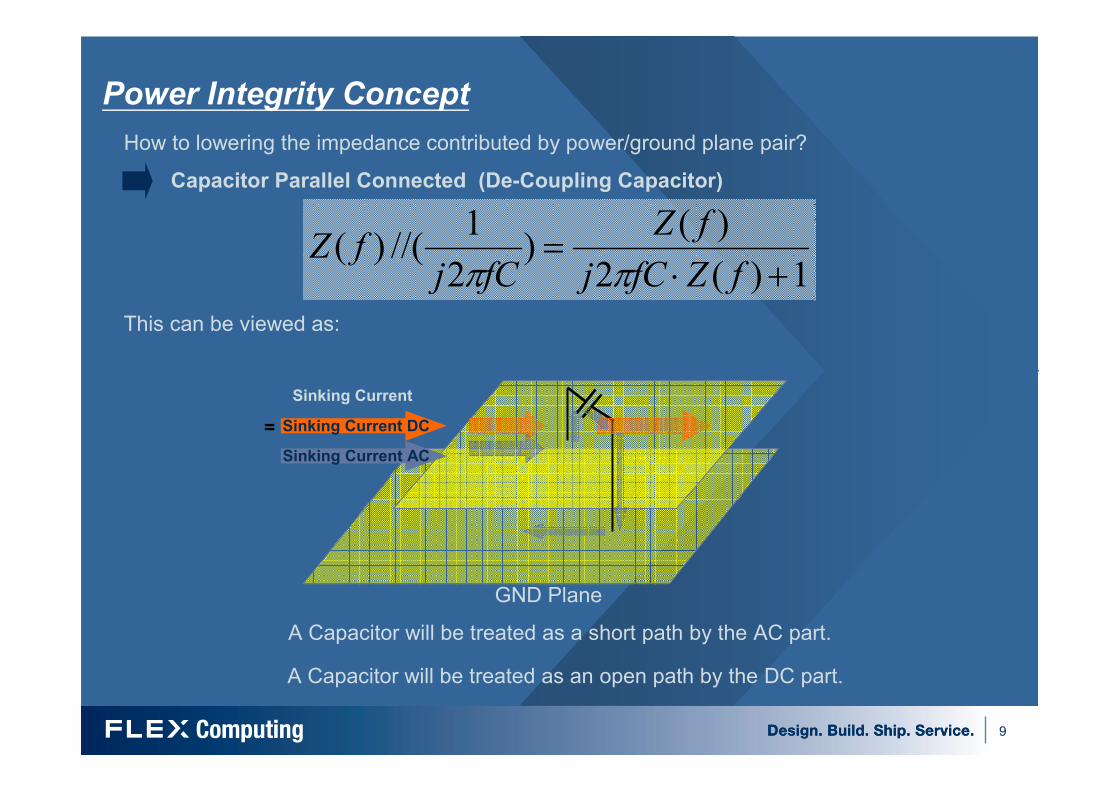
How to lowering the impedance contributed by power/ground plane pair?
Capacitor Parallel Connected (De-Coupling Capacitor)
1)(2
)()
2
1//()(
+⋅=
fZfCj
fZ
fCjfZ
ππ
This can be viewed as:
GND Plane
Sinking Current
= Sinking Current DC
Sinking Current AC
A Capacitor will be treated as a short path by the AC part.
A Capacitor will be treated as an open path by the DC part.

10
Power Integrity ConceptIf the analysis result is fail, how’s the impact?
1. Add Capacitors
2. Modify the layers:
1. Add Layers
2. Add trace Width
3. Location of VRM and Sense
4. VIA numbers and location
AC AnalysisDC Analysis
Change the geometry of
the Power Distribution
System
i. Floor planning
ii. Shape geometry
Change the geometry of
the Power Distribution
System
Modify the Schematics
To speed up the design procedure and reduce the frequency of modifying the PDS’s geometry,
we will frozen the PDS’s geometry after the DC Analysis and simply modify the capacitor’s size,
number and location of capacitors, that is:
Modify the location of
capacitors
DC Analysis AC Analysis
Modify the Schematics
Modify the location of
capacitors
Change the geometry of
the Power Distribution
System

11
� Introduction
� Power Integrity Concept
� DC Analysis for Power Integrity
� AC Analysis for Power Integrity
� Summary
� Q & A
1. Observe from Frequency Domain
2. Observe from Time Domain

12
DC Analysis for Power Integrity
i. Power DC helps us to track down
the voltage distribution along the
Power Delivery Path.
ii. Power DC helps us to generate
clear table to judge the simulation
result Pass or Fail.
iii. The whole procedure is easy and
fast.
Voltage Drop:

13
DC Analysis for Power IntegrityCurrent Density:
i. Power DC helps us to find out if
there’s any critical location where
exist a large amount of current.
ii. By the capability of Power DC to
analyze the current density
distribution, we can find out if
there’s any redundant moat on the
plane.
iii. The whole procedure is easy and
fast.

14
� Introduction
� Power Integrity Concept
� DC Analysis for Power Integrity
� AC Analysis for Power Integrity
� Summary
� Q & A
1. Observe from Frequency Domain
2. Observe from Time Domain
15
� Introduction
� Power Integrity Concept
� DC Analysis for Power Integrity
� AC Analysis for Power Integrity
� Summary
� Q & A
1. Observe from Frequency Domain
2. Observe from Time Domain

16
Observe from frequency domainImpedance Plot File:
i. Power SI helps us to get more information such as S-
parameter than only the impedance.
ii. The whole procedure is easy and fast.

17
Observe from frequency domainImpedance Plot File:
Target
Impedance
Frequency
(Hz)
Impedance
(Ohm)
Target
Impedance
Frequency
(Hz)
Impedance
(Ohm)
i. Power SI gives us more
freedom to choice solutions -
> not only to suppress the
impedance against certain
frequency where the
impedance exceed the target
impedance.
ii. For Example, we can see
there’s a resonant frequency
at 400KHz. While choosing
220uF as the solution, which
is against 300KHz, it only
takes 5 capacitor to lower the
impedance under the target.
iii. While choosing capacitors
which is against 400KHz as
the solution, it will takes 8
capacitor to lower the
impedance under the target.

18
Observe from frequency domainImpedance Spatial Distribution:
i. Power SI helps us to find out the best
location to add capacitors where the
impedance is largest.
ii. Power SI’s Spatial mode allows us to
customized the current sink as Gaussian
Pulse or any other waveforms described in
PWL to ignore the effect above certain
frequency range.
iii. Of course, Power SI’s Spatial mode also
allows us to set the current sink as an unit
impulse, what we do in Extraction mode to
extract the S-parameter and Z-parameter.
iv. The whole procedure is easy and fast.
19
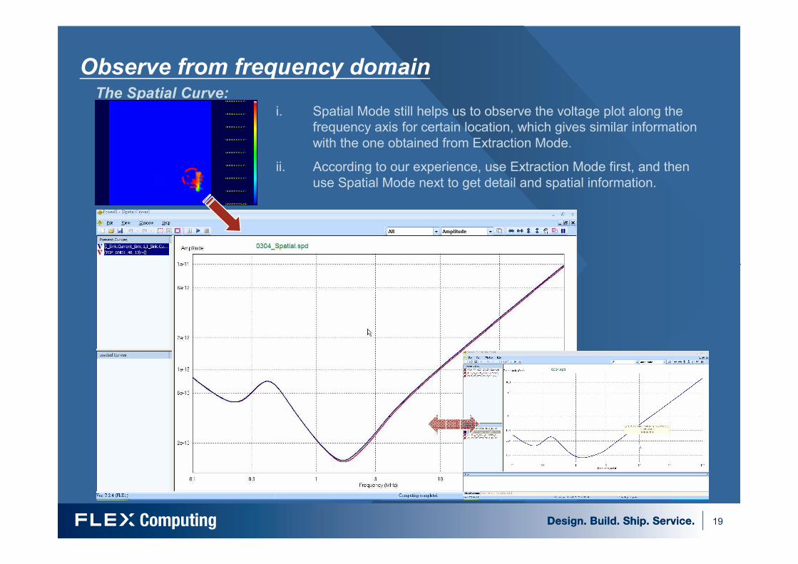
Observe from frequency domainThe Spatial Curve:
i. Spatial Mode still helps us to observe the voltage plot along the
frequency axis for certain location, which gives similar information
with the one obtained from Extraction Mode.
ii. According to our experience, use Extraction Mode first, and then
use Spatial Mode next to get detail and spatial information.

20
� Introduction
� Power Integrity Concept
� DC Analysis for Power Integrity
� AC Analysis for Power Integrity
� Summary
� Q & A
1. Observe from Frequency Domain
2. Observe from Time Domain

21
Observe from Time domain
Time Domain Analysis is necessary for PDS of which the SPEC has definition about: 1.
The maximum current slew rate, 2. The maximum overshoot voltage above VID, and 3.
The maximum overshoot time duration above VID. 4.Load Line
For Example, if we have:
The Maximum Current Slew Rate of 300A/µs
The Maximum Overshoot Voltage above VID=50mV
The Maximum Overshoot Time Duration above VID=25µs
The Load Line:Vcc(max) = VID – 0.8mΩ*Icc
Vcc(min) = VID – 0.8mΩ*Icc-30mV

22
Observe from Time domain
V 1 2 PWL(0 1.061 50n 1.061 450n 0.965 4450n 0.965 4900n 1.061 8900n 1.061 9350n 0.965 13350n 0.965)
I 1 2 PWL (0 30 50n 30 450n 150 4450n 150 4900n 30 8900n 30 9350n 150 13350n 150 )
In time domain analysis, we can customize the current sink and the voltage source
(i.e. the VRM) according to the maximum current slew rate and the load line defined
in VRD Spec and use Speed2000 to emulate the behavior.
For Example:
VRM
Current
Sink
Simulation Result:

23
� Introduction
� Power Integrity Concept
� DC Analysis for Power Integrity
� AC Analysis for Power Integrity
� Summary
� Q & A
1. Observe from Frequency Domain
2. Observe from Time Domain
24
Summary
� As the transferring rate increase, Power Integrity becomes a more and
more critical issue in modern high speed design.
� A complete power integrity analysis should cover both frequency domain
and time domain.
� Spatial distribution of capacitors would affect how efficiency our solution
is.
� Due to the concern of cost and time-to-market, Flextronics chooses
Sigrity’s tool set to ensure our design is safe to work properly.

25
Q&A

26
Thank you~ Design. Build. Ship. Service.