1 Plant & Electrical Distribution Systems Module ENGE 303 Module ENGE 303 [email protected]...
86
1 Plant & Electrical Plant & Electrical Distribution Systems Distribution Systems Module ENGE 303 Module ENGE 303 [email protected] [email protected] [email protected] [email protected] Tel No: 0141 331 …. Tel No: 0141 331 …. Room M… Room M… Week 1 Week 1
-
Upload
elfreda-hancock -
Category
Documents
-
view
219 -
download
0
Transcript of 1 Plant & Electrical Distribution Systems Module ENGE 303 Module ENGE 303 [email protected]...

11
Plant & Electrical Distribution Plant & Electrical Distribution SystemsSystems
Module ENGE 303Module ENGE 303
[email protected]@gcal.ac.uk [email protected]@logis-tech.co.uk
Tel No: 0141 331 ….Tel No: 0141 331 ….
Room M…Room M…
Week 1Week 1

22
Recommended TextRecommended Text
J.O Bird, J.O Bird, Electrical Circuit Theory and Electrical Circuit Theory and TechnologyTechnology, Revised edition, Revised edition
(Chapters 7, 8, 9)(Chapters 7, 8, 9)
T.Floyd, T.Floyd, Electronic Fundamentals, Electronic Fundamentals, Circuits, Devices and Applications, 6Circuits, Devices and Applications, 6thth EditionEdition
(Chapter 7)(Chapter 7)

33
MagnetismMagnetism
and and
ElectromagnetismElectromagnetism

44
The Magnetic FieldThe Magnetic Field
A permanent magnet has a magnetic A permanent magnet has a magnetic field surrounding it. field surrounding it.
Consists of Consists of lines of forcelines of force that that radiate from the north pole to the radiate from the north pole to the south pole and back to the north pole south pole and back to the north pole through the magnetic material.through the magnetic material.

55
Figure 1Figure 1 Magnetic lines of force around a bar Magnetic lines of force around a bar magnet.magnet.

66
The Magnetic FieldThe Magnetic Field Consists of lines of force, (or flux lines), Consists of lines of force, (or flux lines),
that radiate from the north pole (N) to that radiate from the north pole (N) to the south pole (S) and back to the N. the south pole (S) and back to the N. pole through the magnetic material.pole through the magnetic material.
The many lines surround the magnet in The many lines surround the magnet in 3 dimensions. 3 dimensions.
Lines shrink to the smallest possible Lines shrink to the smallest possible size and blend together;- although they size and blend together;- although they do not touch. do not touch.
Forms a continuous magnetic field Forms a continuous magnetic field surrounding the magnet.surrounding the magnet.

77
Figure 2Figure 2 Magnetic attraction and Magnetic attraction and repulsionrepulsion

88
Fig. 3Fig. 3 Effect of (a) nonmagnetic and (b) magnetic Effect of (a) nonmagnetic and (b) magnetic materials on a magnetic field.materials on a magnetic field.

99
Magnetic Flux, Magnetic Flux, ΦΦ The group of force lines going from the N. The group of force lines going from the N.
pole to the S. pole of a magnet is called pole to the S. pole of a magnet is called the magnetic flux, symbolized by the magnetic flux, symbolized by ΦΦ (phi). (phi).
No. of lines of force in a magnetic field No. of lines of force in a magnetic field determines the value of the flux. determines the value of the flux.
The more lines of force, the greater the The more lines of force, the greater the flux and the stronger the magnetic field.flux and the stronger the magnetic field.
Unit of magnetic flux is the weber (Wb) Unit of magnetic flux is the weber (Wb) One weber = 10One weber = 1088 lines. lines.
1010
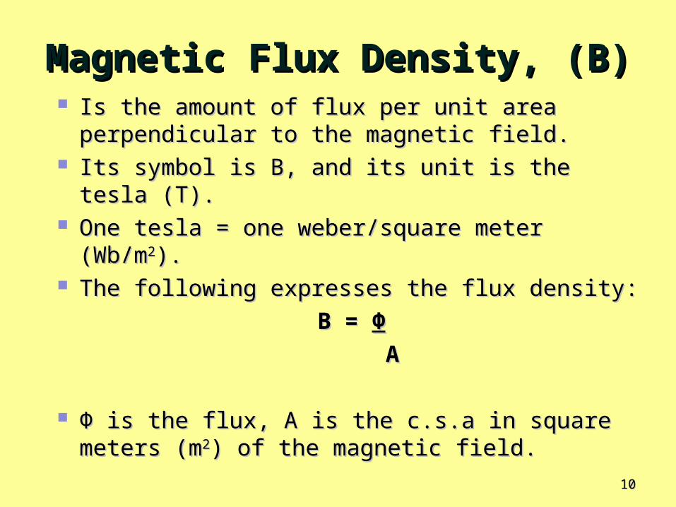
Magnetic Flux Density, (B)Magnetic Flux Density, (B) Is the amount of flux per unit area Is the amount of flux per unit area
perpendicular to the magnetic field. perpendicular to the magnetic field. Its symbol is B, and its unit is the tesla (T). Its symbol is B, and its unit is the tesla (T). One tesla = one weber/square meter One tesla = one weber/square meter
(Wb/m(Wb/m22). ). The following expresses the flux density:The following expresses the flux density:
B =B = ΦΦ
AA
ΦΦ is the flux, A is the c.s.a in square is the flux, A is the c.s.a in square meters (mmeters (m22) of the magnetic field.) of the magnetic field.

1111
The GaussThe Gauss The tesla (T) is the SI unit for flux The tesla (T) is the SI unit for flux
density, another unit called the density, another unit called the gauss, from the CGS (centimeter-gauss, from the CGS (centimeter-gram-second) system, is sometimes gram-second) system, is sometimes used used ((101044 gauss = 1T). gauss = 1T).
The instrument used to measure flux The instrument used to measure flux density is the gaussmeter.density is the gaussmeter.

1212
Example 1Example 1 Find the flux density in a magnetic Find the flux density in a magnetic
field in which the flux in 0.1mfield in which the flux in 0.1m2 2 is is 800800μμWb.Wb.
SolutionSolution
B = B = ΦΦ/A /A
= 800= 800μμWb/0.1mWb/0.1m22
= 8000= 8000μμTT

1313
Example 2Example 2 A magnetic pole face has a rectangular A magnetic pole face has a rectangular
section having dimensions 200 mm by 100 section having dimensions 200 mm by 100 mm. If the total flux emerging from the mm. If the total flux emerging from the pole is 150 pole is 150 μμ Wb. Calculate the flux Wb. Calculate the flux density.density.
Solution:Solution: ΦΦ = 150 = 150 μμ Wb = 150 x 10 Wb = 150 x 10-6-6 Wb Wb c.s.a = 200 x 100 = 20000 mmc.s.a = 200 x 100 = 20000 mm2 2 = 20000 x 10= 20000 x 10-6-6 m m22
Flux Density, B = Flux Density, B = ΦΦ/A /A
= 150 x 10= 150 x 10-6-6/20000 x 10/20000 x 10-6-6
= 0.0075 T or 7.5mT= 0.0075 T or 7.5mT

1414
How Materials Become How Materials Become MagnetisedMagnetised
Ferromagnetic materials become magnetised when Ferromagnetic materials become magnetised when placed in the magnetic field of a magnet. placed in the magnetic field of a magnet.
We have all seen a permanent magnet pick up We have all seen a permanent magnet pick up paper clips, nails, or iron filings. paper clips, nails, or iron filings.
Objects becomes magnetised under the influence Objects becomes magnetised under the influence of the permanent magnetic field and becomes of the permanent magnetic field and becomes attracted to the magnet. attracted to the magnet.
When removed from the magnetic field, object When removed from the magnetic field, object tends to lose its magnetism.tends to lose its magnetism.
Ferromagnetic materials have minute magnetic Ferromagnetic materials have minute magnetic domains created within their atomic structure by domains created within their atomic structure by the orbital motion and spin of electrons. the orbital motion and spin of electrons.
These domains can be viewed as very small bar These domains can be viewed as very small bar magnets with N. and S. poles. magnets with N. and S. poles.

1515
Figure 4Figure 4 Magnetic domains in (a) an unmagnetized Magnetic domains in (a) an unmagnetized and in (b) a magnetised materialand in (b) a magnetised material..

1616
Figure 5Figure 5 Operation of a magnetic Operation of a magnetic switchswitch
Application Application ExampleExample

1717
Figure 6Figure 6 Connection of a typical perimeter alarm Connection of a typical perimeter alarm systemsystem

1818
Quiz 1Quiz 1 When the North poles of two When the North poles of two
magnets are placed close together, magnets are placed close together, do they repel or attract each other?do they repel or attract each other?
Ans: The North Poles repelAns: The North Poles repel What is magnetic flux?What is magnetic flux?Ans: Magnetic flux is the group of Ans: Magnetic flux is the group of
lines of force that make up a lines of force that make up a magnetic field.magnetic field.
What is the flux density when What is the flux density when ΦΦ = = 4.54.5μμWb and A = 5 x 10Wb and A = 5 x 10⁻³ -3 mm22??
Ans: B = Ans: B = ΦΦ/A = 900/A = 900μμTT

1919
ElectromagnetismElectromagnetism
Is the production of a magnetic Is the production of a magnetic field by current in a conductor. field by current in a conductor.
Many types of useful devices Many types of useful devices such as tape recorders, electric such as tape recorders, electric motors, speakers, solenoids, and motors, speakers, solenoids, and relays are based on relays are based on electromagnetism.electromagnetism.

2020
Fig. 7Fig. 7 Magnetic field around a current-carrying Magnetic field around a current-carrying conductorconductor

2121
Figure 8Figure 8 Visible effects of an Visible effects of an electromagnetic fieldelectromagnetic field

2222
Fig. 9Fig. 9 Magnetic lines of force around a current-carrying Magnetic lines of force around a current-carrying conductorconductor

2323
Fig. 10Fig. 10 Illustration of right-hand Illustration of right-hand rulerule

2424
Electromagnetic Electromagnetic PropertiesProperties
Permeability (Permeability (μμ) )
The Relative Permeability (The Relative Permeability (μμrr) )
Reluctance, S (RReluctance, S (RMM))

2525
Permeability (Permeability (μμ)) Ease with which a magnetic field can be established Ease with which a magnetic field can be established
in a given material is measured by the in a given material is measured by the permeabilitypermeability of that material. of that material.
Higher the permeability, a magnetic field can be Higher the permeability, a magnetic field can be established easierestablished easier
Symbol Symbol μμ; its value varies depending on material. ; its value varies depending on material.
μμo, o, permeability of a vacuum is permeability of a vacuum is 44ππ X 10 X 10-7-7 Wb/At.m Wb/At.m (weber/ampere-turn.meter) and is used as a (weber/ampere-turn.meter) and is used as a reference. reference.
Ferromagnetic materials typically have;Ferromagnetic materials typically have; permeabilities hundreds of times larger than that of a vacuumpermeabilities hundreds of times larger than that of a vacuum include iron, steel, and their alloys.include iron, steel, and their alloys.

2626
The Relative PermeabilityThe Relative Permeability
((μμrr) ) of a material is the ratio of its of a material is the ratio of its absolute permeability (absolute permeability (μμ) to the ) to the permeability of a vacuum (permeability of a vacuum (μμoo). ).
Since Since μμrr is a ratio, it has no units. is a ratio, it has no units.
μμrr = = μμ
μμoo

2727
ReluctanceReluctance (S) (S) Opposition to the establishment of a Opposition to the establishment of a
magnetic field in a material is called magnetic field in a material is called reluctance (reluctance (SS). ).
Value of reluctance is directly Value of reluctance is directly proportional to the length (proportional to the length (ℒℒ) of the ) of the magnetic path, and inversely magnetic path, and inversely proportional to the permeability (proportional to the permeability (μμ) ) and to the c.s.a. (A) of the material;and to the c.s.a. (A) of the material;
S S = = ℒℒμμA (At/Wb)A (At/Wb)

2828
Example 2Example 2 What is the reluctance of a material What is the reluctance of a material
that has a length of 0.05 m, a cross-that has a length of 0.05 m, a cross-sectional area of 0.012 msectional area of 0.012 m22, and a , and a permeability of 3500 permeability of 3500 μμWb/At.m?Wb/At.m?
Solution:Solution:
SS = = ℒℒ/ / μμA A
= 0.05/ (3500 x 10= 0.05/ (3500 x 10-6 -6 Wb/At.m) Wb/At.m) (0.012m(0.012m22) )
= 1190 At/Wb= 1190 At/Wb

2929
Magnetomotive Force Magnetomotive Force (mmf)(mmf)
Current in a conductor produces a magnetic Current in a conductor produces a magnetic field. field.
Force that produces the magnetic field is Force that produces the magnetic field is called the magnetomotive force (mmf). called the magnetomotive force (mmf).
Unit of mmf, (At), is established on the basis Unit of mmf, (At), is established on the basis of the current in a single loop (turn) of wire. of the current in a single loop (turn) of wire.
Formula for mmf is:Formula for mmf is:Fm = NI Fm = NI
Fm is the magnetomotive force, N is the no. Fm is the magnetomotive force, N is the no. of turns of wire, I is the current in amperes.of turns of wire, I is the current in amperes.

3030
Figure 11Figure 11 A basic magnetic A basic magnetic circuitcircuit

3131
Ohm's law for magnetic Ohm's law for magnetic circuitscircuits
The amount of flux depends on the The amount of flux depends on the magnitude of the mmf and on the magnitude of the mmf and on the reluctance of the material, as reluctance of the material, as expressed by:expressed by:
ΦΦ = = FmFm RR

3232
How much flux is established in the How much flux is established in the magnetic path of Fig. 12 if the reluctance magnetic path of Fig. 12 if the reluctance of the material is 0.28 X 10of the material is 0.28 X 1055 At/WB? At/WB?
Example 3Example 3
Figure 12Figure 12

3333
Solution to Example 3Solution to Example 3
ΦΦ = Fm/ = Fm/RR = NI/ = NI/RR = = (5 t) (3 A)(5 t) (3 A)
0.28 X 100.28 X 1055 At/Wb At/Wb
= 5.36 X 10= 5.36 X 10⁻⁴-4 Wb Wb
= 536= 536μμWbWb

3434
Example 4Example 4 There are two amperes of current through a There are two amperes of current through a
wire with 5 turns.wire with 5 turns. (a) (a) What is the mmf?What is the mmf? (b) (b) What is the reluctance of the circuit if What is the reluctance of the circuit if
the flux is 250 the flux is 250 μμWb?Wb?
Solution Solution
(a) (a) N = 5 and I = 2AN = 5 and I = 2A
Fm = NI = (5t)(2A) = Fm = NI = (5t)(2A) = 10 At10 At
(b) R = Fm/(b) R = Fm/ΦΦ = 10At/250 = 10At/250μμWb Wb
= 0.04 X 10= 0.04 X 1066 At/Wb At/Wb
= = 4.0 X 104.0 X 1044 At/Wb At/Wb

3535
The ElectromagnetThe Electromagnet
A basic electromagnet is A basic electromagnet is simply a coil of wire wound simply a coil of wire wound around a core material that around a core material that can be easily magnetised.can be easily magnetised.
The shape of the The shape of the electromagnet can be electromagnet can be designed for various designed for various applications.applications.

3636
Figure 13Figure 13 Reversing the current in the coil causes Reversing the current in the coil causes the electromagnetic field to reverse.the electromagnetic field to reverse.

3737
Figure 14Figure 14 Read/write function on a magnetic Read/write function on a magnetic surface.surface.
Application Application ExamplesExamples

3838
The Magneto – Optical DiskThe Magneto – Optical Disk Uses an electromagnet and laser beams to Uses an electromagnet and laser beams to
read and write (record) data on a read and write (record) data on a magnetic surface.magnetic surface.
Formatted in tracks and sectors similar to Formatted in tracks and sectors similar to magnetic floppy disks and hard disks. magnetic floppy disks and hard disks.
Laser beam precisely directed to an Laser beam precisely directed to an extremely small spot extremely small spot
Capable of storing much more data than Capable of storing much more data than standard magnetic hard disks.standard magnetic hard disks.

3939
Figure 15Figure 15 Basic concept of the magneto-optical Basic concept of the magneto-optical disk.disk.

4040
Electromagnetic DevicesElectromagnetic Devices
Magnetic disk/tape read/write head Magnetic disk/tape read/write head Magneto-optical disk Magneto-optical disk Transformer Transformer SolenoidSolenoid RelayRelay Speaker Speaker

4141
The SolenoidThe Solenoid Is a type of electromagnetic device Is a type of electromagnetic device
that has a movable iron core called that has a movable iron core called a a plunger. plunger.
Movement of this iron core depends Movement of this iron core depends on both an electromagnetic field and on both an electromagnetic field and a mechanical spring force. a mechanical spring force.

4242
Figure 16Figure 16 Basic solenoid Basic solenoid structure.structure.

4343
Figure 17Figure 17 Basic solenoid Basic solenoid operationoperation

4444
The RelayThe Relay
Differs from solenoids in that the Differs from solenoids in that the electromagnetic action is used to electromagnetic action is used to open or close electrical contacts open or close electrical contacts rather than to provide mechanical rather than to provide mechanical movement. movement.

4545
Fig. 18Fig. 18 Basic structure of a single-pole-double- Basic structure of a single-pole-double-throw relaythrow relay
4646
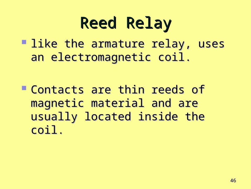
Reed RelayReed Relay like the armature relay, uses an like the armature relay, uses an
electromagnetic coil. electromagnetic coil.
Contacts are thin reeds of magnetic Contacts are thin reeds of magnetic material and are usually located material and are usually located inside the coil.inside the coil.

4747
Figure 20Figure 20 Basic structure of a reed Basic structure of a reed relayrelay

4848
Example 5Example 5 With the aid of a sketch, explain With the aid of a sketch, explain
the operation of the the operation of the electromagnetic relay. electromagnetic relay.
Also provide an example of an Also provide an example of an application of this type of application of this type of device?device?
SolutionSolution
• Reference should be made to Reference should be made to the reed relay and /or the the reed relay and /or the armature relay.armature relay.
• electromagnetic action is used electromagnetic action is used to open or close electrical to open or close electrical contactscontacts
• unenergised/energisedunenergised/energised• StructureStructure• SymbolSymbol

4949
The SpeakerThe Speaker Permanent-magnet speakers are commonly Permanent-magnet speakers are commonly
used and their operation is based on the used and their operation is based on the principle of electromagnetism. principle of electromagnetism.
Constructed with a permanent magnet and Constructed with a permanent magnet and an electromagnet. an electromagnet.
Cone of the speaker consists of a paper-like Cone of the speaker consists of a paper-like diaphragm to which is attached a hollow diaphragm to which is attached a hollow cylinder with a coil around it, forming an cylinder with a coil around it, forming an electromagnet. electromagnet.

5050
Figure 21Figure 21 Basic speaker Basic speaker operationoperation

5151
Fig. 22Fig. 22 The speaker converts audio signal voltages The speaker converts audio signal voltages into sound waves.into sound waves.

5252
Meter MovementMeter Movement d'Arsonval meter movement is the d'Arsonval meter movement is the
most common type used in analog most common type used in analog multimeters. multimeters.
In this type of meter movement, the In this type of meter movement, the pointer is deflected in proportion to pointer is deflected in proportion to the amount of current through a coil. the amount of current through a coil.

5353Figure 23Figure 23 The basic d’Arsonval meter movement The basic d’Arsonval meter movement

5454
Fig. 24Fig. 24 When the electromagnetic field interacts with When the electromagnetic field interacts with the permanent magnetic field, forces are exerted on the the permanent magnetic field, forces are exerted on the rotating coil assembly, causing it to move clockwise and rotating coil assembly, causing it to move clockwise and thus deflecting the pointer.thus deflecting the pointer.
Hugo Gallagher

5555
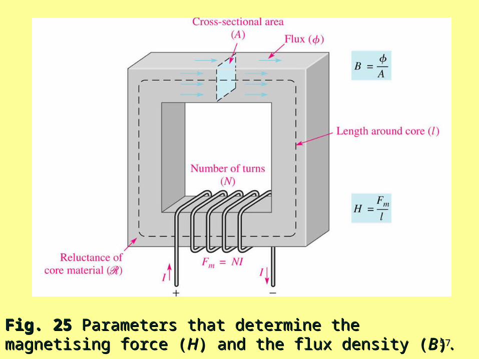
Magnetising Force (H) Magnetising Force (H) Magnetizing force in a material is defined to be the Magnetizing force in a material is defined to be the magnetomotive force magnetomotive force (Fm(Fm) per unit length () per unit length (ℒℒ) of the material.) of the material.
Unit of magnetizing force (H) is ampere-turns per meter Unit of magnetizing force (H) is ampere-turns per meter (At/m).(At/m).
H = H = FmFm ℒℒWhere, Fm Where, Fm = = NI.NI.
NoteNote
Magnetising force depends on the no. of turns (N) of the coil of Magnetising force depends on the no. of turns (N) of the coil of wire, the current (I) through the coil, and the length (wire, the current (I) through the coil, and the length (ℒℒ) of the ) of the
material. material.
It does not depend on the type of material.It does not depend on the type of material.
Hugo Gallagher

5656
Magnetising Force (H)Magnetising Force (H) Since Since ΦΦ = Fm/R, as Fm increases, the flux = Fm/R, as Fm increases, the flux
increases. increases.
Also, magnetising force (H) increases. Also, magnetising force (H) increases.
Recall that; flux density (B) is the flux per Recall that; flux density (B) is the flux per unit c.s.a. (B = unit c.s.a. (B = ΦΦ/A), so B is also /A), so B is also proportional to H. proportional to H.
Curve showing how these two quantities (B Curve showing how these two quantities (B & H) are related is called the B-H curve & H) are related is called the B-H curve (hysteresis curve). (hysteresis curve).
5757
Fig. 25Fig. 25 Parameters that determine the magnetising Parameters that determine the magnetising force (force (HH) and the flux density () and the flux density (BB).).

5858
The Hysteresis CurveThe Hysteresis Curve
HysteresisHysteresis is a characteristic of a is a characteristic of a magnetic material whereby a change in magnetic material whereby a change in magnetisation lags the application of a magnetisation lags the application of a magnetising force. magnetising force.
Magnetising force (H) can be increased Magnetising force (H) can be increased or decreased by varying the current or decreased by varying the current through the coil of wire (reversed by through the coil of wire (reversed by reversing the voltage polarity across reversing the voltage polarity across the coil).the coil).

5959
Fig 26Fig 26 Development of a magnetic hysteresis Development of a magnetic hysteresis curvecurve

6060
Fig: 26(g) Complete B-H Curve ~ The Hysteresis Fig: 26(g) Complete B-H Curve ~ The Hysteresis CurveCurve

6161
Example 6Example 6 A mild steel ring of c.s.a. 4 cm has a A mild steel ring of c.s.a. 4 cm has a
radial air-gap of 3 mm cut into it. If radial air-gap of 3 mm cut into it. If the mean length of the mild steel the mean length of the mild steel path is 300 mm. path is 300 mm.
Calculate the magnetomotive force to Calculate the magnetomotive force to
produce a flux of 0.48 mWb. produce a flux of 0.48 mWb.
(Use B-H curve on page 78) (Use B-H curve on page 78)

6262
Solution to Example 6Solution to Example 6 Two parts to the circuit - mild steel and the Two parts to the circuit - mild steel and the
air-gapair-gap
For the mild steel: For the mild steel: B = B = ΦΦ/A/A =0.48 x 10=0.48 x 10⁻³-3 /4 x 10 /4 x 10-4-4 = 1.2 = 1.2
TT (From B-H curve for mild steel on p78) (From B-H curve for mild steel on p78) when B = 1.2 T, H = 1800 A/m (or close)when B = 1.2 T, H = 1800 A/m (or close)
Hence, m.m.f. for the mild steel Hence, m.m.f. for the mild steel Hl = (1800)(300 x 10Hl = (1800)(300 x 10-3-3) = ) = 540 A540 A

6363
Solution to Example 6 Solution to Example 6 (cont.d)(cont.d)
For the air-gap: For the air-gap: The flux density will be the same in the air-gap as The flux density will be the same in the air-gap as
in thein the mild steel, i.e. 1.2 Tmild steel, i.e. 1.2 T For air, B = For air, B = µµ00H from which, H from which, H = B/H = B/µµ00 = 1.2T/4= 1.2T/4ππ x 10 x 10-7-7 = 954930 A/m= 954930 A/m
Hence the m.m.f. for the air-gap = Hl Hence the m.m.f. for the air-gap = Hl = (954930)(3 = (954930)(3 10 10-3-3) ) = = 2865 A2865 A
Total m.m.f.Total m.m.f. to produce a flux of 0.48 mWb to produce a flux of 0.48 mWb = 540 + 2865 = = 540 + 2865 = 3405 A3405 A

6464
Materials with a low RetentivityMaterials with a low Retentivity Do not retain a magnetic field very well while Do not retain a magnetic field very well while
those with high retentivities exhibit values of those with high retentivities exhibit values of BBRR very close to the saturation value of B. very close to the saturation value of B.
Retentivity in a magnetic material can be an Retentivity in a magnetic material can be an advantage or a disadvantage. advantage or a disadvantage.
In permanent magnets and memory cores ~ In permanent magnets and memory cores ~ high retentivity is required. high retentivity is required.
In ac motors ~ retentivity is undesirableIn ac motors ~ retentivity is undesirable

6565
Electromagnetic InductionElectromagnetic Induction Relative motion between a conductor Relative motion between a conductor
and a magnetic field, a voltage is and a magnetic field, a voltage is produced across the conductor. produced across the conductor.
Resulting voltage is an induced Resulting voltage is an induced voltage. voltage.
Transformers, electrical generators, Transformers, electrical generators, electrical motors, and many other electrical motors, and many other devices possible.devices possible.

6666
Relative MotionRelative Motion When a wire is moved across a When a wire is moved across a
magnetic field, there is a relative motion magnetic field, there is a relative motion between the wire and the magnetic between the wire and the magnetic field. field.
Likewise, when a magnetic field is Likewise, when a magnetic field is moved past a stationary wire, there is moved past a stationary wire, there is also relative motion. also relative motion.
In either case, this relative motion In either case, this relative motion results in an results in an induced voltageinduced voltage ( (vvindind)) . .

6767
Fig. 27Fig. 27 Relative motion between a wire and a Relative motion between a wire and a magnetic fieldmagnetic field

6868
Fig. 28Fig. 28 Polarity of induced voltage depends on Polarity of induced voltage depends on direction of motion.direction of motion.

6969
Fig. 29 Fig. 29 Induced current (iInduced current (iindind) in a load as the wire ) in a load as the wire moves through the magnetic field.moves through the magnetic field.

7070
Fig. 30Fig. 30 Forces on a current-carrying conductor in a Forces on a current-carrying conductor in a magnetic field (motor action).magnetic field (motor action).

7171
Faraday’s LawFaraday’s Law Michael Faraday discovered the principle of Michael Faraday discovered the principle of
electromagnetic induction electromagnetic induction in 1831. in 1831.
Faraday's two observations:Faraday's two observations:
(1) The amount of voltage induced in a coil is (1) The amount of voltage induced in a coil is directly proportional to the rate of change directly proportional to the rate of change of the magnetic field w.r.t. the coil.of the magnetic field w.r.t. the coil.
(2) The amount of voltage induced in a coil is (2) The amount of voltage induced in a coil is directly proportional to the no. of turns of directly proportional to the no. of turns of wire in the coil.wire in the coil.

7272
Fig. 31Fig. 31 A demonstration of Faraday’s first observation: A demonstration of Faraday’s first observation: The amount of induced voltage is directly proportional to The amount of induced voltage is directly proportional to the rate of change of the magnetic field w.r.t. the coil.the rate of change of the magnetic field w.r.t. the coil.

7373
Fig. 32Fig. 32 A demonstration of Faraday’s second A demonstration of Faraday’s second observation: The amount of induced voltage is observation: The amount of induced voltage is directly proportional to the no. of turns in the coildirectly proportional to the no. of turns in the coil

7474
Faraday’s LawFaraday’s Law
The voltage induced The voltage induced across a coil of wire across a coil of wire equals the number of equals the number of turns in the coil times turns in the coil times the rate of change of the rate of change of the magnetic flux.the magnetic flux.

7575
Lenz’s LawLenz’s Law Defines the polarity or direction of Defines the polarity or direction of
the induced voltage.the induced voltage.
When the current through a coil When the current through a coil changes, the polarity of the changes, the polarity of the induced voltage created by the induced voltage created by the changing magnetic field is such changing magnetic field is such that it always opposes the that it always opposes the change in current that caused it.change in current that caused it.

7676
Applications of Applications of Electromagnetic InductionElectromagnetic Induction
an automotive an automotive crankshaft position crankshaft position sensor sensor
dc generator. dc generator.

7777
Automotive Crankshaft Position Automotive Crankshaft Position SensorSensor
An interesting automotive application An interesting automotive application is a type of engine sensor that detects is a type of engine sensor that detects the crankshaft position directly using the crankshaft position directly using electromagnetic induction. electromagnetic induction.
The electronic engine controller in The electronic engine controller in many automobiles uses the position of many automobiles uses the position of the crankshaft the crankshaft to set ignition timingto set ignition timing adjust the fuel control system. adjust the fuel control system.

7878
Fig. 33Fig. 33 A crankshaft position sensor that produces a A crankshaft position sensor that produces a voltage when a tab passes through the air gap of the voltage when a tab passes through the air gap of the magnet.magnet.

7979
Fig. 34Fig. 34 As the tab passes through the air gap of the As the tab passes through the air gap of the magnet, the coil senses a change in the magnetic magnet, the coil senses a change in the magnetic field, and a voltage is induced.field, and a voltage is induced.

8080
Fig. 35Fig. 35 A simplified dc A simplified dc generatorgenerator

8181
Fig. 36Fig. 36 End view of wire loop cutting through the End view of wire loop cutting through the magnetic fieldmagnetic field

8282
Fig. 37Fig. 37 Operation of a basic dc Operation of a basic dc generatorgenerator

8383
Fig. 38Fig. 38 Induced voltage over three rotations of Induced voltage over three rotations of the wire loop in the dc generatorthe wire loop in the dc generator..

8484
Fig. 39Fig. 39 The induced voltage for a two-loop The induced voltage for a two-loop generator. There is much less variation in the generator. There is much less variation in the induced voltage.induced voltage.

8585
Example 7Example 7 A conductor 30 cm long is situated at A conductor 30 cm long is situated at
right-angles to a magnetic field. right-angles to a magnetic field. Calculate the strength of the magnetic Calculate the strength of the magnetic field if a current of 15 A in the conductor field if a current of 15 A in the conductor produces a force on it of 3.6 N.produces a force on it of 3.6 N.
SolutionSolution ℒℒ = 0.3 m, I = 15 A and F = 3.6 N= 0.3 m, I = 15 A and F = 3.6 N F = B I F = B I ℒ => B = F / ℒ => B = F / I I ℒ = 3.6 / 15 x ℒ = 3.6 / 15 x
0.30.3
= 0.80 T= 0.80 T

8686
Example 8Example 8 Find the emf in a Find the emf in a
coil of 200 turns coil of 200 turns when there is a when there is a change of flux of change of flux of 30 mWb linking it 30 mWb linking it in 40 ms.in 40 ms.
SolutionSolution
ΔϕΔϕ = 30 x 10 = 30 x 10-3 -3 WbWb ΔΔt = 40 x 10t = 40 x 10-3 -3 ss
dt
dNE
3
3
1040
1030
x
xNE
Induced emf, EInduced emf, E
VE 150