1 Particle-In-Cell Monte Carlo simulations of a radiation driven plasma Marc van der Velden, Wouter...
19
1 Particle-In-Cell Monte Carlo simulations of a radiation driven plasma Marc van der Velden, Wouter Brok, Vadim Banine, Joost van der Mullen, Gerrit Kroesen. COST Model Inventory Workshop, April 2005
-
date post
20-Dec-2015 -
Category
Documents
-
view
217 -
download
1
Transcript of 1 Particle-In-Cell Monte Carlo simulations of a radiation driven plasma Marc van der Velden, Wouter...

1
Particle-In-Cell Monte Carlo simulations of a
radiation driven plasma
Marc van der Velden, Wouter Brok, Vadim Banine,Joost van der Mullen, Gerrit Kroesen.
COST Model Inventory Workshop, April 2005

2
Kinetic Plasma Model
• Fluid model requires equilibrium assumptions for velocity distributions,
• Kinetic model preferable when
> L or > T plasma sheath near electrode Ignition phase of lamp of low pressure lamp

3
Outline
• PIC-Monte Carlo method,
• EUV generated plasma,
• Simulation Results,
• Summary/Outlook.

4
1D3V model
Particle-In-Cell
Interpolatecharges to grid
Solve Poissonequation
Interpolate E-field at particle position
Collisions at wall
Collisions with neutralsnew velocity
Move particlesF v x
sx
xixi 11xixi 1
1 )(
i
sii x
xx
xA
q
Bi-linear interpolationPoisson equation
00
2
2
ie nne
x
V
x
VVxE iis
1)(
Bi-linear interpolation
m
qEtttvttv
ttvttxttx
)()(
)()()(
21
21
21
Leap-frog scheme
Interpolatecharges to grid
Solve Poissonequation
Interpolate E-field at particle position
Collisions at wall
Collisions with neutralsnew velocity
Move particlesF v x
Interpolatecharges to grid
Solve Poissonequation
Interpolate E-field at particle position
Collisions at wall
Collisions with neutralsnew velocity
Move particlesF v x
Interpolatecharges to grid
Solve Poissonequation
Interpolate E-field at particle position
Collisions at wall
Collisions with neutralsnew velocity
Move particlesF v x
Interpolatecharges to grid
Solve Poissonequation
Interpolate E-field at particle position
Collisions at wall
Collisions with neutralsnew velocity
Move particlesF v x
Interpolatecharges to grid
Solve Poissonequation
Interpolate E-field at particle position
Collisions at wall
Collisions with neutralsnew velocity
Move particlesF v x
Interpolatecharges to grid
Solve Poissonequation
Interpolate E-field at particle position
Collisions at wall
Collisions with neutralsnew velocity
Move particlesF v x
Particle-wall interactionMonte-Carlo Collisions

5
Monte Carlo Collisions
• Charged particles collide with background gas,
• Collision: event that instantaneously changes the velocity, in both magnitude and direction,
• Super particle represents many real particles, but has charge and mass of real electron/ion,
].1,0[,)1ln(
exp1)(
rndvvN
rndt
tvvNtp
bg
bg
time to next collision:
• Probability p(t) of collision after time t:

6
Null-collision method
• Problem: Velocity dependent collision frequency: c = N (v) v• Solution: Introduce extra dummy process c = max{N (v) v}
• In case of collision: Draw random number to determine process.
0 100 200 300
0
10
20
30
Co
llisi
on
fre
qu
en
cy (
E)
[MH
z]
Electron energy [eV]
Elastic Elastic+Excitation Elastic+Excitation+Ionization Elastic+Excitation+Ionization
+Null-Collision
Null-Collision
• Processes: elastic electron scattering
e- + Ar e- + Ar collisional excitation
e- + Ar e- + Ar*
electron-impact ionizatione- + Ar 2e- + Ar+
elastic ion scatteringAr+ + Ar Ar+ + Ar
charge exchange collisionsAr+ + Ar Ar + Ar+
7
0.0
0.2
0.4
0.6
0.8
1.0
0
30
60
90
120
150
1800.0
0.2
0.4
0.6
0.8
1.0
1 eV 10 eV 30 eV
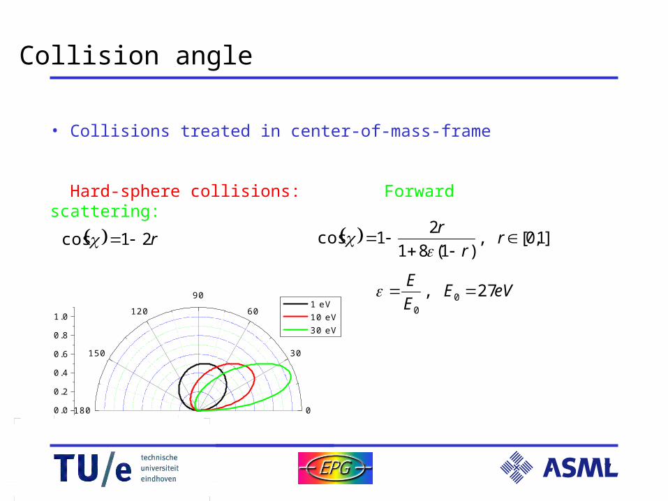
Collision angle
• Collisions treated in center-of-mass-frame
Hard-sphere collisions: Forward scattering:
]1,0[,)1(81
21cos
r
r
r
r21cos
eVEE
E27, 0
0

8
Next generation lithography
• Diffraction limited: Smaller wavelength is smaller features!• EUV-radiation: 13,5 nm wavelength,
• Very small absorption lengths (typically 0.1 mm):
1) Optical path contained within vacuum setup, p = 0.01 – 1 Pa,
2) refractive optics reflective optics

9
Radiation driven plasma
• EUV radiation from plasma source,• Argon background gas: p = 0.01 – 1 Pa,
Photo-ionization of background gas,creating a plasma!
Atom
EUV photonh = 92 eV
Fast electronEkin = 76 eV
Slow ion
WallPlasmasheath
Bulk plasma
• Very expensive!Quasi-
neutrality
• Formation of a plasma sheath,
• Ions accelerated towards walls,
• Sputtering of optics?
• Influence of photo-electric effect?-
--
electrons
--
-ionsPhoto-
electrons
--
-Vpl

10
Photo-electric effect
• Photons absorbed in mirror cause collision cascade and secondary electron emission; • Case 1) no photo-effect
• Case 2) hot photo-electrons Inelastic reflection: Ee= h - W
• Case 3) cold photo-electrons Electron scattering inside mirror: distribution of electron energies S(E). Above certain energy S(E) independent of photon energy.
0 10 20 30 400.00
0.05
0.10
0.15
En
erg
y d
istr
ibu
tion
fun
ctio
n
Electron energy [eV]
4
2
)(
6)(
WE
EWES

11
‘Numerical’ Setup
5 cm
• 1-D equidistant grid, 300 grid points: x < D.
• 105 super particles, one super particle represents 109 real particles.
• Time steps of 1 ps: t « (2 / e), t < (x / <v>).
• Boundary Conditions: mirror and wall are grounded.
Multi-layer mirror
Wall

12
0.0 0.2 0.4 0.6 0.8 1.0
1E14
1E15
1E16
Pla
sma
de
nsi
ty [m
-3]
Position [cm]
10 ns electrons 10 ns ions
0.0 0.2 0.4 0.6 0.8 1.0
1E14
1E15
1E16
Pla
sma
de
nsi
ty [m
-3]
Position [cm]
10 ns electrons 10 ns ions 50 ns electrons 50 ns ions
Results(1): plasma density
• 100 ns EUV pulse,
• Sheath build-up,
• Low-density, ionization degree 10-5.
0.0 0.2 0.4 0.6 0.8 1.0
1E14
1E15
1E16
Pla
sma
de
nsi
ty [m
-3]
Position [cm]
10 ns electrons 10 ns ions 50 ns electrons 50 ns ions 500 ns electrons 500 ns ions

13
0.0 0.2 0.4 0.6 0.8 1.0
1014
1015
1016
Pla
sma
den
sity
[m-3]
Position [cm]
10 ns electrons 10 ns ions 50 ns electrons 50 ns ions 500 ns electrons 500 ns ions
Results(1): plasma density
• 100 ns EUV pulse,
• Sheath build-up,
• Low-density, ionization degree 10-5.
No photo-effect Cold ph-e-
Hot ph-e-
0.0 0.2 0.4 0.6 0.8 1.0
1014
1015
1016
Pla
sma
de
nsi
ty [m
-3]
Position [cm]
10 ns electrons 10 ns ions 50 ns electrons 50 ns ions 500 ns electrons 500 ns ions
0.0 0.2 0.4 0.6 0.8 1.0
1014
1015
1016
Pla
sma
dens
ity [m
-3]
Position [cm]
10 ns electrons 10 ns ions 50 ns electrons 50 ns ions 500 ns electrons 500 ns ions

14
0 1 2 3 4 5
0
20
40
60
80
100
Mea
n el
ectr
on e
nerg
y [e
V]
Position [cm]
10 ns 50 ns 100 ns 200 ns 1000 ns
Results(2): electron energy
• Electron energy decreases:
1) Most-energetic electrons reach walls first,2) Electron-impact ionization,3) Excitation.
No photo-electrons Cold photo-electrons
Hot photo-electrons
0 1 2 3 4 5
0
20
40
60
80
100
Mea
n el
ectr
on e
nerg
y [e
V]
Position [cm]
10 ns 50 ns 100 ns 200 ns 1000 ns
0.00 0.01 0.02 0.03 0.04 0.05
0
20
40
60
80
100
Mea
n el
ectr
on e
nerg
y [e
V]
Position [cm]
10 ns 50 ns 100 ns 200 ns 1000 ns

15
0 1 2 3 4 5
0
20
40
60
Pot
entia
l [V
]
Position [cm]
10 ns 50 ns 100 ns 200 ns 1000 ns
Results(3): potential
• Initially negative potential at mirror due to photo-electrons,
• Plasma potential max 80 V.
• Photo-effect has effect on potential
0 1 2 3 4 50
20
40
60
80
Pot
entia
l [V
]
Position [cm]
10 ns 50 ns 100 ns 200 ns 1000 ns
No photo-electrons Cold photo-electrons
0 1 2 3 4 5-40
-20
0
20
40
60
80
Pot
entia
l [V
]
Position [cm]
10 ns 50 ns 100 ns 200 ns 1000 ns
Hot photo-electrons

16
Results(4): ion impact
• Ions accelerated by sheath potential drop,
• Ions reach wall after EUV pulse,
.
4,
1 221
21
mm
mmUU surfthr
• Maximum ion energy close to sputter threshold.
0.0 0.2 0.4 0.6 0.8 1.0
0
10
20
30
40
50 no photo-electrons hot photo-electrons cold photo-electrons
EU
V-in
ten
sity [a.u
.]
EUV off
Ave
rag
e io
nim
pa
ct e
ne
rgy
[eV
]
Time [s]
EUV on
SputterThreshold

17
Results(6): Including Ar2+
• EUV-photons energetic enough for double photo-ionization of argon.
• Sputtering dominated by Ar2+.
0.0 0.2 0.4 0.6 0.8 1.0
0
20
40
60
80
100 No photo-electrons Ar+
No photo-electrons Ar2+
Cold photo-electrons Ar+
Cold photo-electrons Ar2+
EU
V-in
ten
sity [a.u
.]
EUV off
Ave
rag
e io
nim
pa
ct e
nerg
y [e
V]
Time [s]
EUV on
SputterThreshold
single double single double0
1
Sp
utt
er
Ra
te [
a.u
.]
No photo-electrons Cold photo-electrons
Ar+
Ar2+

18
Summary
• With PIC-MCC it is possible to simulate a plasma far from equilibrium.
• Photo-effect has influence on sputter rate.
• Sputtering will be modest as kinetic energy of most ions will be below sputtering threshold.

19
Outlook
• Experimental verification:
Energy sensitive mass-spectrometry, Absolute Line Intensity measurements,
Sputter yield and sputter rate measurements. Thompson scattering (?) Energy resolved Secondary electron yield measurements.