
1 Outline Principles of congestion control TCP congestion control.
45
1 Outline • Principles of congestion control • TCP congestion control
-
date post
19-Dec-2015 -
Category
Documents
-
view
248 -
download
2
Transcript of 1 Outline Principles of congestion control TCP congestion control.

1
Outline
• Principles of congestion control
• TCP congestion control

2
Principles of Congestion Control
Congestion:
• informally: “too many sources sending too much data too fast for network to handle”
• different from flow control!
• manifestations:
– lost packets (buffer overflow at routers)
– long delays (queueing in router buffers)
• a top-10 problem!

3
Approaches towards congestion control
End-end congestion control:
• no explicit feedback from network
• congestion inferred from end-system observed loss, delay
• approach taken by TCP
Network-assisted congestion control:
• routers provide feedback to end systems
– single bit indicating congestion (SNA, DECbit, TCP/IP ECN, ATM)
– explicit rate sender should send at
Two broad approaches towards congestion control:

4
TCP Congestion Control
• end-end control (no network assistance)
• sender limits transmission:
LastByteSent-LastByteAcked
CongWin
• Roughly,
• CongWin is dynamic, function of perceived network congestion
How does sender perceive congestion?
• loss event = timeout or 3 duplicate acks
• TCP sender reduces rate (CongWin) after loss event
three mechanisms:
– AIMD
– slow start
– conservative after timeout events
rate = CongWin
RTT Bytes/sec

5
TCP AIMD
8 Kbytes
16 Kbytes
24 Kbytes
time
congestionwindow
multiplicative decrease: cut CongWin in half after loss event
additive increase: increase CongWin by 1 MSS every RTT in the absence of loss events: probing
Long-lived TCP connection

6
TCP Slow Start
• When connection begins, CongWin = 1 MSS
– Example: MSS = 500 bytes & RTT = 200 msec
– initial rate = 20 kbps
• available bandwidth may be >> MSS/RTT
– desirable to quickly ramp up to respectable rate
When connection begins, increase rate exponentially fast until first loss event

7
TCP Slow Start (more)
• When connection begins, increase rate exponentially until first loss event:
– double CongWin every RTT
– done by incrementing CongWin for every ACK received
• Summary: initial rate is slow but ramps up exponentially fast
Host A
one segment
RT
T
Host B
time
two segments
four segments
8
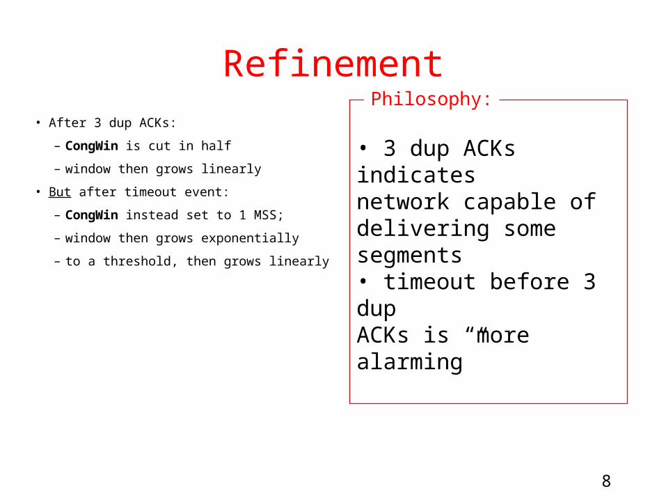
Refinement• After 3 dup ACKs:
– CongWin is cut in half
– window then grows linearly
• But after timeout event:
– CongWin instead set to 1 MSS;
– window then grows exponentially
– to a threshold, then grows linearly
• 3 dup ACKs indicates network capable of delivering some segments• timeout before 3 dup ACKs is “more alarming”
Philosophy:

9
Refinement (more)Q: When should the
exponential increase switch to linear?
A: When CongWin gets to 1/2 of its value before timeout.
Implementation:
• Variable Threshold
• At loss event, Threshold is set to 1/2 of CongWin just before loss event

10
Summary: TCP Congestion Control
• When CongWin is below Threshold, sender in slow-start phase, window grows exponentially.
• When CongWin is above Threshold, sender is in congestion-avoidance phase, window grows linearly.
• When a triple duplicate ACK occurs, Threshold set to CongWin/2 and CongWin set to Threshold.
• When timeout occurs, Threshold set to CongWin/2 and CongWin is set to 1 MSS.

11
TCP sender congestion control
Event State TCP Sender Action Commentary
ACK receipt for previously unacked data
Slow Start (SS)
CongWin = CongWin + MSS, If (CongWin > Threshold) set state to “Congestion Avoidance”
Resulting in a doubling of CongWin every RTT
ACK receipt for previously unacked data
CongestionAvoidance (CA)
CongWin = CongWin+MSS * (MSS/CongWin)
Additive increase, resulting in increase of CongWin by 1 MSS every RTT
Loss event detected by triple duplicate ACK
SS or CA Threshold = CongWin/2, CongWin = Threshold,Set state to “Congestion Avoidance”
Fast recovery, implementing multiplicative decrease. CongWin will not drop below 1 MSS.
Timeout SS or CA Threshold = CongWin/2, CongWin = 1 MSS,Set state to “Slow Start”
Enter slow start
Duplicate ACK
SS or CA Increment duplicate ACK count for segment being acked
CongWin and Threshold not changed

12
TCP throughput
• What’s the average throughout ot TCP as a function of window size and RTT?
– Ignore slow start
• Let W be the window size when loss occurs.
• When window is W, throughput is W/RTT
• Just after loss, window drops to W/2, throughput to W/2RTT.
• Average throughout: .75 W/RTT

13
Fairness goal: if K TCP sessions share same bottleneck link of bandwidth R, each should have average rate of R/K
TCP connection 1
bottleneckroutercapacity R
TCP connection 2
TCP Fairness

14
Why is TCP fair?Two competing sessions:
• Additive increase gives slope of 1, as throughout increases
• multiplicative decrease decreases throughput proportionally
R
R
equal bandwidth share
Connection 1 throughput
Con
nect
ion
2 th
roug
h pu t
congestion avoidance: additive increaseloss: decrease window by factor of 2
congestion avoidance: additive increaseloss: decrease window by factor of 2

15
Fairness (more)
Fairness and UDP
• Multimedia apps often do not use TCP
– do not want rate throttled by congestion control
• Instead use UDP:
– pump audio/video at constant rate, tolerate packet loss
• Research area: TCP friendly
Fairness and parallel TCP connections
• nothing prevents app from opening parallel cnctions between 2 hosts.
• Web browsers do this
• Example: link of rate R supporting 9 cnctions;
– new app asks for 1 TCP, gets rate R/10
– new app asks for 11 TCPs, gets R/2 !

Midterm Review
In class, 3:30-5:00 pm, Mon. 2/9
Closed Book
One 8.5” by 11” sheet of paper permitted (single side)

Lecture 1
• Internet Architecture
• Network Protocols
• Network Edge
• A taxonomy of communication networks

• The fundamental question: how is data transferred through net (including edge & core)?
• Communication networks can be classified based on how the nodes exchange information:
A Taxonomy of Communication Networks
Communication Networks
SwitchedCommunication
Network
BroadcastCommunication
Network
Circuit-Switched
Communication Network
Packet-Switched
Communication Network
Datagram Network
Virtual Circuit Network
TDM FDM

Packet Switching: Statistical Multiplexing
Sequence of A & B packets does not have fixed pattern statistical multiplexing.
In TDM each host gets same slot in revolving TDM frame.
A
B
C10 MbsEthernet
1.5 Mbs
D E
statistical multiplexing
queue of packetswaiting for output
link

Packet Switching versus Circuit Switching
• Circuit Switching
– Network resources (e.g., bandwidth) divided into “pieces” for allocation
– Resource piece idle if not used by owning call (no sharing)
– NOT efficient !
• Packet Switching:
– Great for bursty data
– Excessive congestion: packet delay and loss
– protocols needed for reliable data transfer, congestion control

Datagram Packet Switching
• Each packet is independently switched
– Each packet header contains destination address which determines next hop
– Routes may change during session
• No resources are pre-allocated (reserved) in advance
• Example: IP networks

Virtual-Circuit Packet Switching
• Hybrid of circuit switching and packet switching
– All packets from one packet stream are sent along a pre-established path (= virtual circuit)
– Each packet carries tag (virtual circuit ID), tag determines next hop
• Guarantees in-sequence delivery of packets
• However, packets from different virtual circuits may be interleaved

Lecture 2
• Network access and physical media
• Internet structure and ISPs
• Delay & loss in packet-switched networks
• Protocol layers, service models

Internet structure: network of networks
• “Tier-3” ISPs and local ISPs
– last hop (“access”) network (closest to end systems)
– Tier-3: Turkish Telecom, Minnesota Regional Network
Tier 1 ISP
Tier 1 ISP
Tier 1 ISP
NAP
Tier-2 ISPTier-2 ISP
Tier-2 ISP Tier-2 ISP
Tier-2 ISP
localISPlocal
ISPlocalISP
localISP
localISP Tier 3
ISP
localISP
localISP
localISP
Local and tier- 3 ISPs are customers ofhigher tier ISPsconnecting them to rest of Internet

Four sources of packet delay
• 1. processing:
– check bit errors
– determine output link
A
B
propagation
transmission
processingqueueing
• 2. queueing
– time waiting at output link for transmission
– depends on congestion level of router

Delay in packet-switched networks
3. Transmission delay:
• R=link bandwidth (bps)
• L=packet length (bits)
• time to send bits into link = L/R
4. Propagation delay:
• d = length of physical link
• s = propagation speed in medium (~2x10⁸ m/sec)
• propagation delay = d/s
A
B
propagation
transmission
processingqueueing
Note: s and R are very different quantities!

Internet protocol stack• application: supporting network
applications
– FTP, SMTP, STTP
• transport: host-host data transfer
– TCP, UDP
• network: routing of datagrams from source to destination
– IP, routing protocols
• link: data transfer between neighboring network elements
– PPP, Ethernet
• physical: bits “on the wire”
application
transport
network
link
physical
Application Layer• Principles of app layer protocols
• Web and HTTP
• FTP
• Electronic Mail: SMTP, POP3, IMAP
• DNS
• Socket Programming
• Web Caching

HTTP connections
Nonpersistent HTTP
• At most one object is sent over a TCP connection.
• HTTP/1.0 uses nonpersistent HTTP
Persistent HTTP
• Multiple objects can be sent over single TCP connection between client and server.
• HTTP/1.1 uses persistent connections in default mode
• HTTP Message, Format, Response, Methods• HTTP cookies

Response Time of HTTP
Nonpersistent HTTP issues:
• requires 2 RTTs per object
• OS must work and allocate host resources for each TCP connection
• but browsers often open parallel TCP connections to fetch referenced objects
Persistent HTTP
• server leaves connection open after sending response
• subsequent HTTP messages between same client/server are sent over connection
Persistent without pipelining:
• client issues new request only when previous response has been received
• one RTT for each referenced object
Persistent with pipelining:
• default in HTTP/1.1
• client sends requests as soon as it encounters a referenced object
• as little as one RTT for all the referenced objects

FTP: separate control, data connections
• FTP client contacts FTP server at port 21, specifying TCP as transport protocol
• Client obtains authorization over control connection
• Client browses remote directory by sending commands over control connection.
• When server receives a command for a file transfer, the server opens a TCP data connection to client
• After transferring one file, server closes connection.
FTPclient
FTPserver
TCP control connection
port 21
TCP data connectionport 20
• Server opens a second TCP data connection to transfer another file.
• Control connection: “out of band”
• FTP server maintains “state”: current directory, earlier authentication

Electronic Mail: SMTP [RFC 2821]• uses TCP to reliably transfer
email message from client to
server, port 25
• direct transfer: sending
server to receiving server
user mailbox
outgoing message queue
mailserver
useragent
useragent
useragent
mailserver
useragent
useragent
mailserver
useragent
SMTP
SMTP
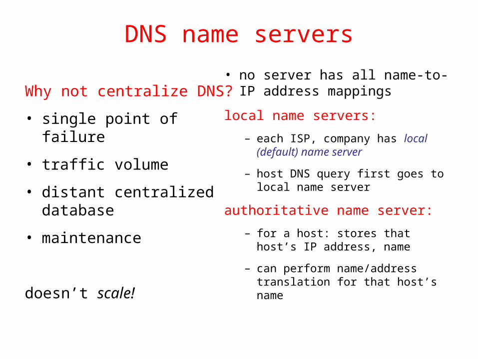
DNS name servers
• no server has all name-to-IP address mappings
local name servers:
– each ISP, company has local (default) name server
– host DNS query first goes to local name server
authoritative name server:
– for a host: stores that host’s IP address, name
– can perform name/address translation for that host’s name
Why not centralize DNS?
• single point of failure
• traffic volume
• distant centralized database
• maintenance
doesn’t scale!

DNS example
Root name server:
• may not know authoritative name server
• may know intermediate name server: who to contact to find authoritative name server
requesting hostsurf.eurecom.fr
www.cs.nwu.edu
root name server
local name serverdns.eurecom.fr
1
23
4 5
6
authoritative name serverdns.cs.nwu.edu
intermediate name serverdns.nwu.edu
7
8
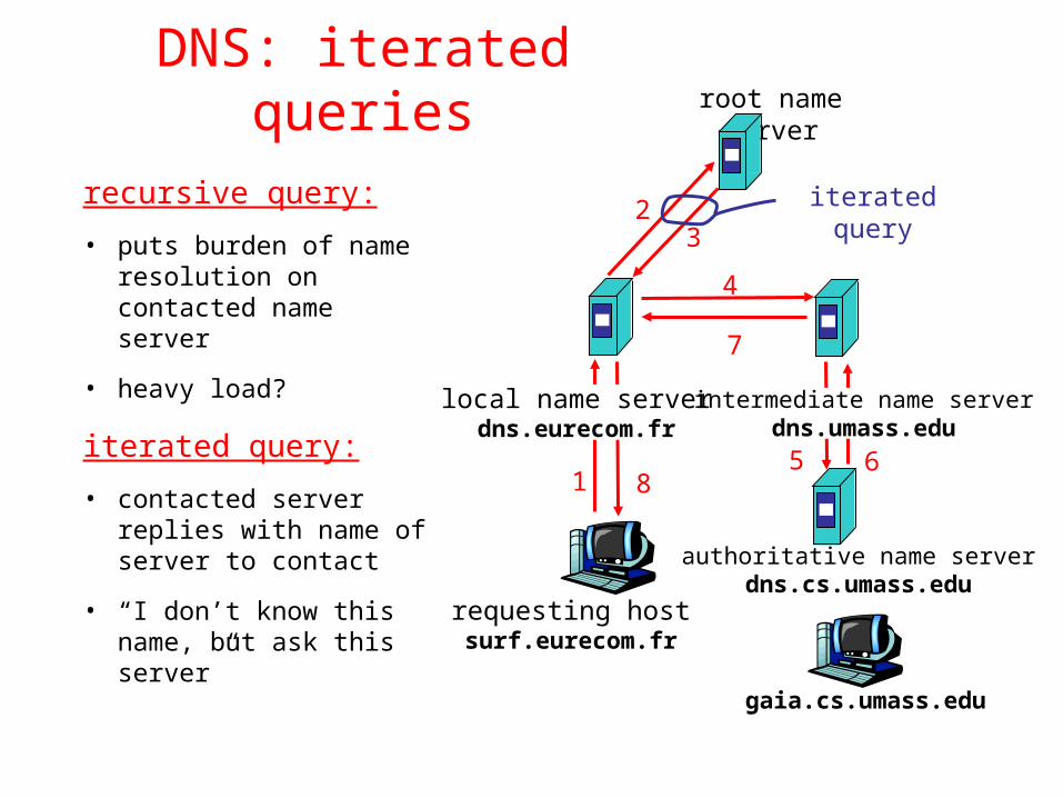
DNS: iterated queries
recursive query:
• puts burden of name resolution on contacted name server
• heavy load?
iterated query:
• contacted server replies with name of server to contact
• “I don’t know this name, but ask this server”
requesting hostsurf.eurecom.fr
gaia.cs.umass.edu
root name server
local name serverdns.eurecom.fr
1
23
4
5 6
authoritative name serverdns.cs.umass.edu
intermediate name serverdns.umass.edu
7
8
iterated query

Web caches (proxy server)
• user sets browser: Web accesses via cache
• browser sends all HTTP requests to cache
– object in cache: cache returns object
– else cache requests object from origin server, then returns object to client
• Why web caching?
Goal: satisfy client request without involving origin server
client
Proxyserver
client
HTTP request
HTTP request
HTTP response
HTTP response
HTTP request
HTTP response
origin server
origin server

Caching example (3)Install cache
• suppose hit rate is .4
Consequence
• 40% requests will be satisfied almost immediately
• 60% requests satisfied by origin server
• utilization of access link reduced to 60%, resulting in negligible delays (say 10 msec)
• total delay = Internet delay + access delay + LAN delay
= .6*2 sec + .6*.01 secs + milliseconds < 1.3 secs
originservers
public Internet
institutionalnetwork 10 Mbps LAN
1.5 Mbps access link
institutionalcache

Transport Layer
• Transport-layer services
• Multiplexing and demultiplexing
• Connectionless transport: UDP
• Principles of reliable data transfer
• TCP
– Segment structures
– Flow control
– Congestion control

Demultiplexing• UDP socket identified
by two-tuple:
(dest IP address, dest port number)
• When host receives UDP segment:
– checks destination port number in segment
– directs UDP segment to socket with that port number
• TCP socket identified by 4-tuple:
– source IP address
– source port number
– dest IP address
– dest port number
• recv host uses all four values to direct segment to appropriate socket

UDP: User Datagram Protocol [RFC 768]
Why is there a UDP?
• no connection establishment (which can add delay)
• simple: no connection state at sender, receiver
• small segment header
• no congestion control: UDP can blast away as fast as desired
source port # dest port #
32 bits
Applicationdata
(message)
UDP segment format
length checksum
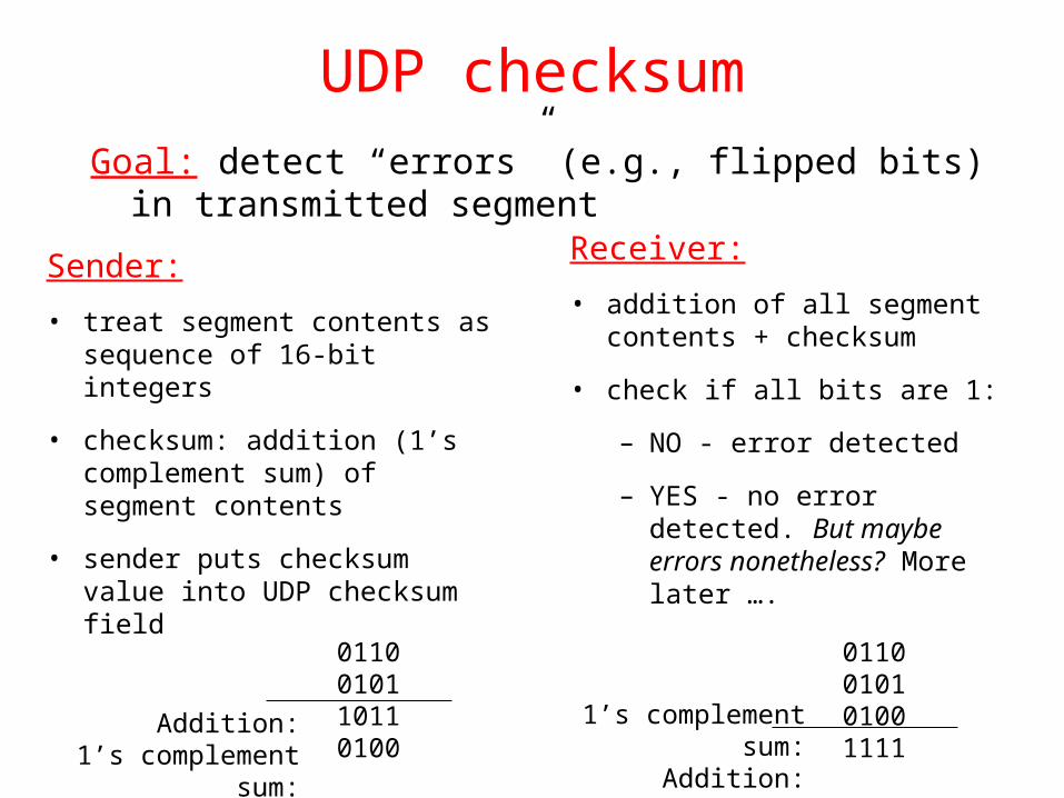
UDP checksum
Sender:
• treat segment contents as sequence of 16-bit integers
• checksum: addition (1’s complement sum) of segment contents
• sender puts checksum value into UDP checksum field
Receiver:
• addition of all segment contents + checksum
• check if all bits are 1:
– NO - error detected
– YES - no error detected. But maybe errors nonetheless? More later ….
Goal: detect “errors” (e.g., flipped bits) in transmitted segment
0110010110110100
Addition:1’s complement sum:
0110010101001111
1’s complement sum:Addition:

Go-Back-NSender:
• k-bit seq # in pkt header
• “window” of up to N, consecutive unack’ed pkts allowed
• ACK(n): ACKs all pkts up to, including seq # n - “cumulative ACK”
– may deceive duplicate ACKs (see receiver)
• Single timer for all in-flight pkts
• timeout(n): retransmit pkt n and all higher seq # pkts in window

Selective Repeat
• receiver individually acknowledges all correctly received pkts
– buffers pkts, as needed, for eventual in-order delivery to upper layer
• sender only resends pkts for which ACK not received
– sender timer for each unACKed pkt
• sender window
– N consecutive seq #’s
– again limits seq #s of sent, unACKed pkts

Selective repeat: sender, receiver windows

TCP segment structure
source port # dest port #
32 bits
applicationdata
(variable length)
sequence number
acknowledgement numberReceive window
Urg data pnterchecksum
FSRPAUheadlen
notused
Options (variable length)
URG: urgent data (generally not used)
ACK: ACK #valid
PSH: push data now(generally not used)
RST, SYN, FIN:connection estab(setup, teardown
commands)
# bytes rcvr willingto accept
countingby bytes of data(not segments!)
Internetchecksum
(as in UDP)


![Linuxcon 2012 student workshop Extending TCP Congestion Control Algorithm … · 2017-11-07 · TFWC (TCP-Friendly Window Control) ※[1] • Smooth congestion control • TCP-Friendly](https://static.fdocuments.us/doc/165x107/5f09b4257e708231d4281ce1/linuxcon-2012-student-workshop-extending-tcp-congestion-control-algorithm-2017-11-07.jpg)


