1-Optimization-of-well-performance-by-use-of-a-semi-permanent ...
30
Optimization of well performance by use of a semi-permanent dynamic desander By Asle Sandven / Ted Brueren MSc. SPE SMN European Sand Management Forum 26-27 March 2014 2013-03-26 Classification: Open
Transcript of 1-Optimization-of-well-performance-by-use-of-a-semi-permanent ...

Optimization of well performance by use of a semi-permanent dynamic desander
By Asle Sandven / Ted Brueren MSc.
SPE SMN European Sand Management Forum 26-27 March 2014
2013-03-26 Classification: Open

Agenda
• Background information
• Sand management challenge
• Solution
• Result

The Gullfaks field
• Located in the northern part of the
Norwegian North Sea
• Production start-up in 1986
• Initial recoverable reserve ~2.1 bn bbl
• Production peak ~605 000 bbl/d in
1994
• Today approx. 110 000 bbl/d
Background information – Challenge – Solution - Result

The Gullfaks field
• The Gullfaks field has been developed by:
− Three large concrete platforms
− Three satellite fields with subsea
wells
• Recovery factor today approx. 62 %
• Recovery ambition 74 %. Obtained by:
− Horizontal and extended wells
− New completion
− EOR technology (f.e. WAG injection)
− Subsea compression
− Sand control technology
Background information – Challenge – Solution - Result

Earlier sand management on Gullfaks C
• Sand trap located at inlet to the test
separator
• Current acceptance criteria per well
(ASR): max.15 g/hr in sand trap
− Sand trap typically captures 1 to 5
% of total sand production
− Criteria corresponds to 0.3 to 1.5
kg/hr of sand per well
Background information – Challenge – Solution - Result

Producer 34/10-C-19
• Drilled and completed in 1993/1994.
Re-completed in 2002
• Sand rate rapidly exceeds ASR criteria
after sand clean-up
− The well flow is therefore choked
back
− The flow may then be too low to lift
out sand to surface
− Over time sand will then
accumulate in the wellbore
− Result: Sand plug formed
Background information – Challenge – Solution - Result
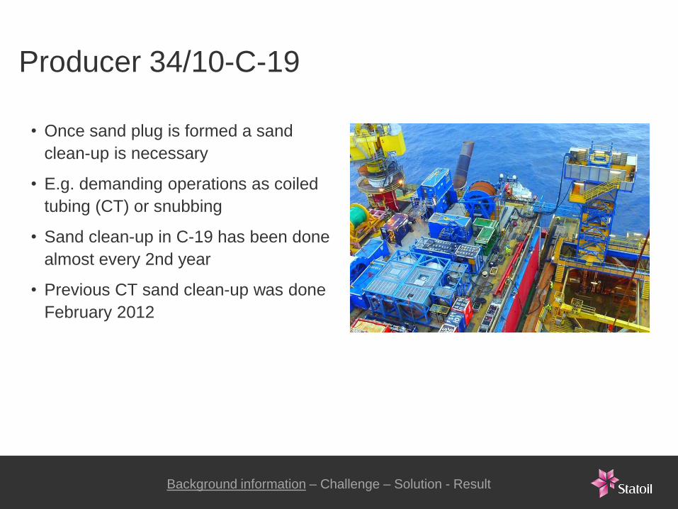
Producer 34/10-C-19
• Once sand plug is formed a sand
clean-up is necessary
• E.g. demanding operations as coiled
tubing (CT) or snubbing
• Sand clean-up in C-19 has been done
almost every 2nd year
• Previous CT sand clean-up was done
February 2012
Background information – Challenge – Solution - Result

0
100
200
300
400
500
600
700
Aug-96 Jan-98 May-99 Oct-00 Feb-02 Jun-03 Nov-04 Mar-06 Aug-07 Dec-08 May-10 Sep-11 Jan-13
Producer 34/10-C-19 - Average Oil rate (Sm3/D)
Background information – Challenge – Solution - Result

CT Sand desander package
• Desander
• Choke manifold
− manually operated
• Control cabin
• 3 x sand skips
• Emergency shutdown valve (ESD)
Background information – Challenge – Solution - Result

Drawbacks of CT Sand desander package
Background information – Challenge – Solution - Result
• Insufficient sand separation
• Well shut-in when emptying
desander
• New rig up for each well
• Sand sent to shore for handling
• Manually operated choke
• Big footprint
• Location in conflict with other
operations
• Qualified as temporary equipment
NORSOK Z-015
• Pressure rated to 100 bar. Not
according to rig specs (345 bar)

Requirements new desander package
Desander functionality
• More efficient separation required
Need of two desanders
Option to flow through
desanders in either series or
parallel
• Constant flow without interruption
Emptying of desander without
shutting down flow
Possibility to bypass
desander
Background information – Challenge – Solution - Result

Requirements new desander package
Operational functionality
• Easy access to all wells
No pipe handling between
each well flowing
Flexibility to route flow to
either HP or LP test separator
• Easy sand handling offshore
No skips for sand storing
• Remote operating of choke
Background information – Challenge – Solution - Result

Requirements new desander package
Desander location
• Avoid conflict with other operations
Need to find new placement
Preferably at production
mezzanin deck (XT-deck)
Background information – Challenge – Solution - Result

Requirements new desander package
Desander location
• Avoid conflict with other operations
Need to find new placement
Preferably at production
mezzanin deck (XT-deck)
• At production mezzanin deck
Limited space available
Limited height available
access through 2x2 m2
opening
Need to reduce size of de-
sander unit dramatically
Background information – Challenge – Solution - Result

Requirements new desander package
Rig requirements
• Not being the weakest link
Pressure tested according to
rig specs
Erosion resistant
Automatic pressure release if
rig shuts down
No emergency shutdown
valve (ESV)
Background information – Challenge – Solution - Result

Solution: semi-permanent dynamic desander
Dual 5kPSI Desander Unit
• Small foot print
− (LxWxH: 2.0 x 2.0 x 3.2m)
• Weight: 8.5 tons
• Dual desander in same frame
− Serie and parallel flow mode
− Option to bypass one desander
• 5000 psi / 345 bar pressure rating
Background information – Challenge – Solution - Result

Solution: semi-permanent dynamic desander
Dual 5kPSI Desander Unit
• Closed system sand handling
− No manual handling of sand
• Separation of solids down to 20 micron
• Monitoring of:
− flowrate
− pressure
− temperature
− amount of sand separated from flow
Background information – Challenge – Solution - Result
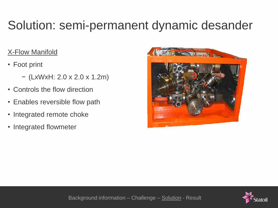
Solution: semi-permanent dynamic desander
X-Flow Manifold
• Foot print
− (LxWxH: 2.0 x 2.0 x 1.2m)
• Controls the flow direction
• Enables reversible flow path
• Integrated remote choke
• Integrated flowmeter
Background information – Challenge – Solution - Result

Solution: semi-permanent dynamic desander
Combine Desander unit with X-Flow
• Minimized slot space needed
− LxWxH: 2.0 x 2.0 x 4.4
• Access to wells on both south and north shaft
• Enables flow to either LP or HP separator
• Built with erosion resistant material:
− Duplex UNS31803
− Tungsten Carbide
Background information – Challenge – Solution - Result
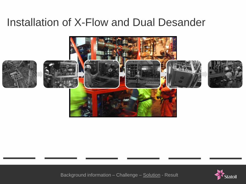
Installation of X-Flow and Dual Desander
Lifting
X-Flow Guiding
X-Flow
X-Flow
in
place
Lifting
de-
sander
Guiding
de-
sander
De-
sander
in place
Background information – Challenge – Solution - Result
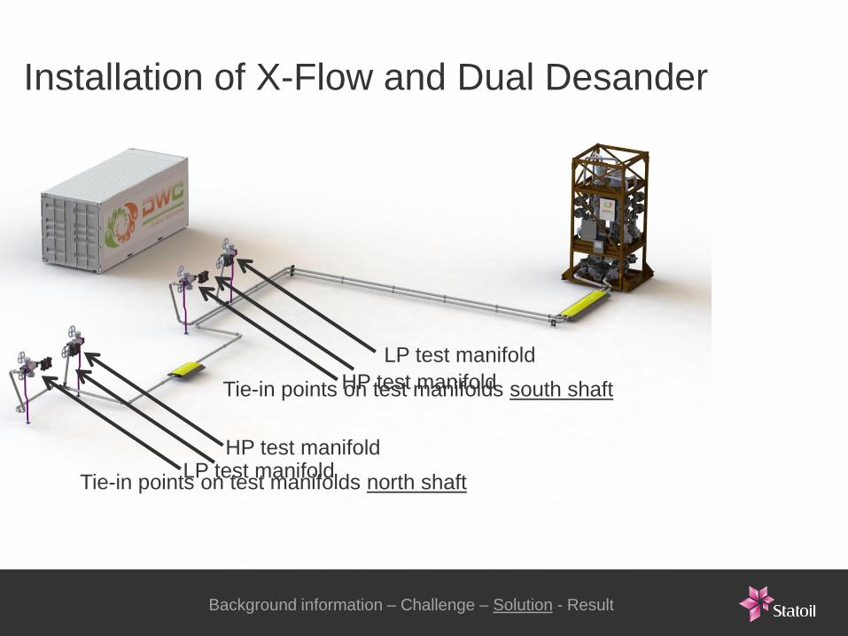
Installation of X-Flow and Dual Desander
Tie-in points on test manifolds south shaft
Tie-in points on test manifolds north shaft
LP test manifold
LP test manifold
HP test manifold
HP test manifold
Background information – Challenge – Solution - Result
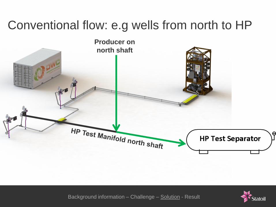
Conventional flow: e.g wells from north to HP
Background information – Challenge – Solution - Result
Producer on
north shaft

New flow path: e.g. wells from north to HP
Background information – Challenge – Solution - Result
Producer on
north shaft

New flow path of wells – animation
2013-12-01 25 Classification: Open
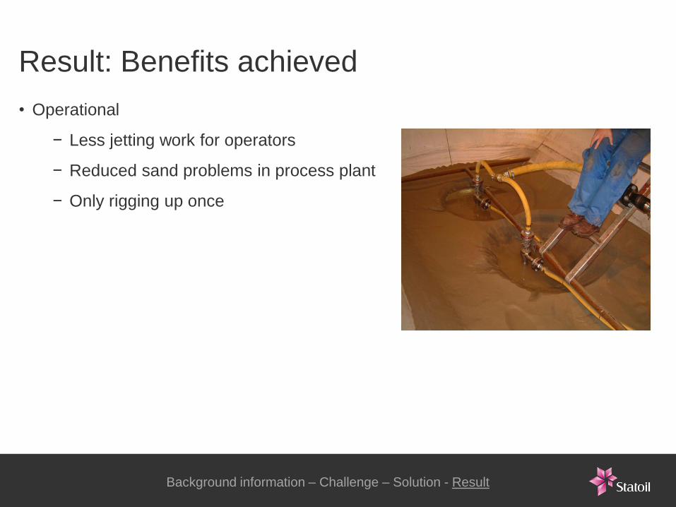
Result: Benefits achieved
Background information – Challenge – Solution - Result
• Operational
− Less jetting work for operators
− Reduced sand problems in process plant
− Only rigging up once
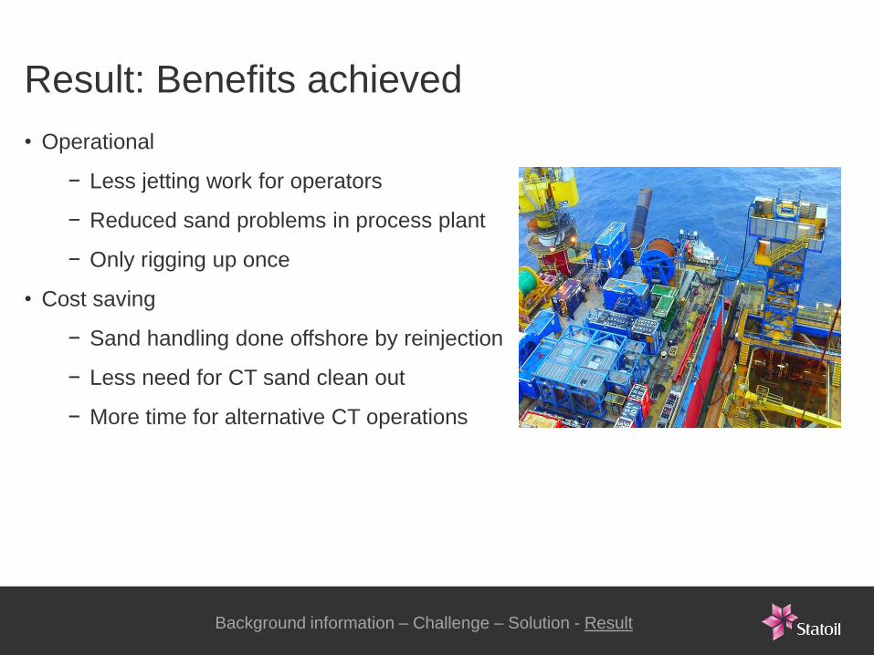
Result: Benefits achieved
Background information – Challenge – Solution - Result
• Operational
− Less jetting work for operators
− Reduced sand problems in process plant
− Only rigging up once
• Cost saving
− Sand handling done offshore by reinjection
− Less need for CT sand clean out
− More time for alternative CT operations
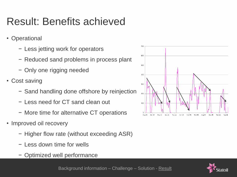
Result: Benefits achieved
• Operational
− Less jetting work for operators
− Reduced sand problems in process plant
− Only one rigging needed
• Cost saving
− Sand handling done offshore by reinjection
− Less need for CT sand clean out
− More time for alternative CT operations
• Improved oil recovery
− Higher flow rate (without exceeding ASR)
− Less down time for wells
− Optimized well performance
Background information – Challenge – Solution - Result

0
100
200
300
400
500
600
700
Aug-96 Jan-98 May-99 Oct-00 Feb-02 Jun-03 Nov-04 Mar-06 Aug-07 Dec-08 May-10 Sep-11 Jan-13
Producer 34/10-C-19 - Average Oil rate (Sm3/D)

Result: Optimized well performance
Background information – Challenge – Solution - Result

Optimization of well performance by use
of a semi-permanent dynamic desander
Ted Brueren MSc.
Well Intervention Engineer
E-mail address: [email protected]
Tel: +4791151049 www.statoil.com
2013-03-26 Classification: Open