1 On to Object Design Chapter 14 Applying UML and Patterns.
27
1 On to Object Design Chapter 14 Applying UML and Patterns
-
Upload
daisy-horn -
Category
Documents
-
view
235 -
download
1
Transcript of 1 On to Object Design Chapter 14 Applying UML and Patterns.
1
On to Object Design
Chapter 14
Applying UML and Patterns

2
Agile Modeling and UML Two of the aims of Agile modeling:
Reduce drawing overhead Model to understand and communicate
In a era of rapid change, documentation tends to have less value Therefore primary purpose of modeling is not to
document Tools that read code and reverse engineer it to
create diagrams like Rational Rose, Eclipse or Visual Studio.

3
Limit time spent drawing A few hours or at most one day of
diagramming should do most of the work for a three week iteration.
Occasional short sessions of modeling during the iteration can clarify any concepts that still need to be understood.
UML is only an ancillary tool to object design. The real skill is the design, not the diagramming.

4
Dynamic and Static Models Dynamic models such as interaction
diagrams (sequence or communication diagrams) help design logic, code behavior, and method bodies.
Static Models such as class diagrams help define packages, class names, attributes, and method signatures.
Switch back and forth during sessions.
5
Dynamic Models Most of the challenging, interesting, and
useful design work is dynamic modeling. Dynamic UML models include sequence,
communication, state machine and deployment diagrams
Interaction diagrams are where we apply design patterns such as GRASP. If the most important skill in object design is
assigning behavior to objects, this is when it usually takes place.

6
Static Models Static models, give the overall structure to our
software, and allow us to divide the work into manageable and maintainable chunks.
Static UML models include class, package, and deployment diagrams.
7
CRC Cards Alternative to UML Object Design is Class,
Responsibility, Collaboration (CRC) cards popularized by Kent Beck in eXtreme Programming.
Interaction Diagram Notation
Chapter 15
Applying UML and Patterns
Craig Larman
9
Introduction Why do objects exist?
To perform an activity to help fulfill a system’s purpose
Interaction Diagrams are used to model system dynamics How do objects change state? How do objects interact (message passing)?
10
Sequence Diagrams
An Interaction Diagram is a generalization of two specialized UML diagram types: Sequence and Communication
Sequence diagrams illustrate object interactions arranged in time sequence Emphasize the time ordering of messages Object linkages are implied, but not explicitly
shown

11
Communication Diagrams
An Interaction Diagram is a generalization of two specialized UML diagram types
Communication diagrams illustrate object interactions organized around the objects and their links to each other Emphasize the structural organization of objects Explicitly show object linkages
Communication and Sequence diagrams are semantically equivalent, however, they may not show the same information
12
Interaction Diagrams Are Valuable Interaction Diagrams provide a thoughtful,
cohesive, common starting point for programs Patterns, principles, and idioms can be
applied to improve the quality of the Interaction Diagrams
13
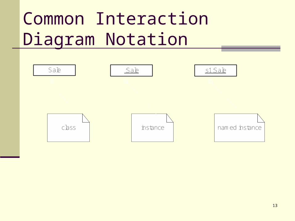
Common Interaction Diagram Notation
class instance named instance
:Sale s1:SaleSale
14
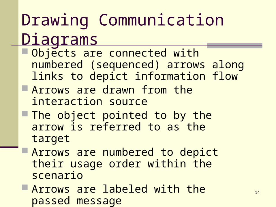
Drawing Communication Diagrams Objects are connected with numbered
(sequenced) arrows along links to depict information flow
Arrows are drawn from the interaction source The object pointed to by the arrow is referred
to as the target Arrows are numbered to depict their usage
order within the scenario Arrows are labeled with the passed message Chain of Messages to minimize coupling

15
Example Communication Diagram
:ClassAInstance
:ClassBInstance
1:
me
ssa
ge
1()
2:
me
ssa
ge
2()
message1()

16
Example Communication Diagram: makePayment
:Register :Sale
:Payment
direction of message
first message
creation indicated with a "create" message
first internal message
parameter instance link line
makePayment(cashTendered:<unspecified>) 1: makePayment(cashTendered:<unspecified>)
1.1
: cr
ea
te: (
cash
Te
nd
ere
d:<
un
spe
cifie
d>
)

17
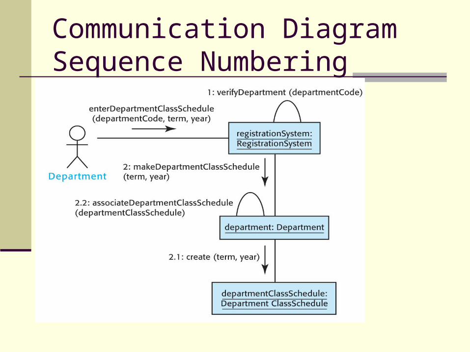
Basic Communication Diagram Notation Link - connection path between two objects (an
instance of an association) Message - represented with a message
expression on an arrowed line between objects Sequence Number - represents the order in
which the flows are used The first message (from actor) is not numbered Messages from the object receiving the initial
message are numbered 1, 2, etc. Messages from the object receiving message 1
are numbered 1.1, 1.2, ect.
Communication Diagram Sequence Numbering
19
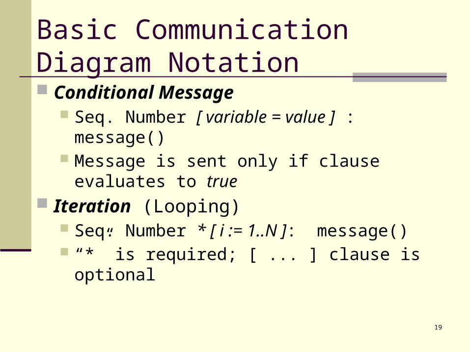
Basic Communication Diagram Notation Conditional Message
Seq. Number [ variable = value ] : message() Message is sent only if clause evaluates to
true Iteration (Looping)
Seq. Number * [ i := 1..N ]: message() “*” is required; [ ... ] clause is optional

20
Sequence Diagrams Correspond to one scenario within a Use Case Identifies the objects involved with each
scenario Identifies the passed messages and actions
that occur during a scenario Identifies the required response of each action

21
Example Sequence Diagram
:ClassAInstance :ClassBInstance
message1()
message2()
message1()

22
Example SequenceDiagram: makePayment()
:Register :Sale
:Payment
an activation box showing the focus of control
makePayment(cashTendered:<unspecified>)
create(cashTendered:<unspecified>)
makePayment(cashTendered:<unspecified>)
X
23
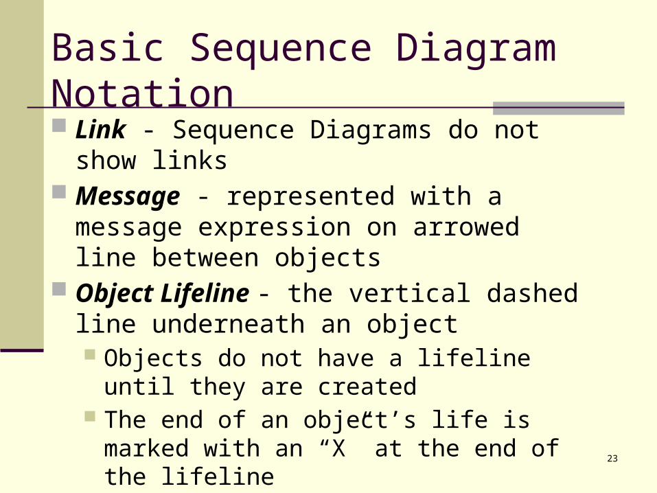
Basic Sequence Diagram Notation Link - Sequence Diagrams do not show links Message - represented with a message
expression on arrowed line between objects Object Lifeline - the vertical dashed line
underneath an object Objects do not have a lifeline until they are
created The end of an object’s life is marked with an
“X” at the end of the lifeline Passage of time is from top to bottom of
diagram

24
Basic Sequence Diagram Notation
Activation - the period of time an object is handling a message (box along lifeline) Activation boxes can be overlaid to depict an
object invoking another method on itself Conditional Message
[ variable = value ] message() Message is sent if clause evaluates to true
Iteration (Looping) * [ i := 1..N ]: message() “*” is required; [ ... ] clause is optional

25
Interaction Diagram Strengths Communication Diagram
Space Economical - flexibility to add new objects in two dimensions
Better to illustrate complex branching, iteration, and concurrent behavior
Sequence Diagram Clearly shows sequence or time ordering of
messages Simple notation
26
Interaction Diagram Weaknesses Communication Diagram
Difficult to see sequence of messages More complex notation
Sequence Diagram Forced to extend to the right when adding new
objects; consumes horizontal space

27
Conclusions Interaction Diagrams usually deserve more
attention than they receive. There is no rule about which diagram to use. Both are often used to emphasize the
flexibility in choice and to reinforce the logic of the operation. Some tools can convert one to the other automatically.