1. GENERALen.shipregister.ua/rules/PartVSubdivision.pdf · · 2017-06-18are not separated by a...
57
PART V. SUBDIVISION 1. GENERAL 1.1 APPLICATION 1.1.1 The requirements of this Part shall cover the following types of ships: .1 passenger ships; .2 oil tankers; .3 fishing vessels having the length L1 100 m and having over 100 persons on board; .4 type А ships and type В ships with reduced freeboard as specified in 4.1.2.1 and 4.1.3.1 of Load Line Rules for Sea-Going Ships; .5 chemical tankers; .6 gas carriers; .7 special purpose ships; .8 supply vessels; .9 ships intended for the carriage of radioactive agents; .10 cargo ships having the length L1 80 m not mentioned above; .11 dry cargo ships having the length L1 80 m (refer to 1.4.9); .12 icebreakers having the length L1 50 m; .13 tugs having the length L1 40 m; .14 dredgers having the length L1 40 m, hopper dredgers having the length L1 60 m; .15 salvage ships; .16 drilling ships; .17 lightships; .18 ships having the ice strengthen- ing marks Ісе4, Ісе5 and Ісе6 in the class notation; .19 berth connected ships used as floating hotels and/or having over 100 persons on board; .20 bulk carriers, ore and combina- tion carriers in service which construc- tion date is specified in Section 5. .21 cargo ships having the length L1 < 100 m other than bulk carriers, and a single cargo hold or cargo holds which are not separated by a bulkhead made watertight up to the freeboard deck (refer to 3.4.13). .22 ro-ro passenger ships – a passen- ger ship carrying more than 12 passen- gers and having closed or open ro-ro spaces or spaces of special category as defined in 1.5.4.3, 1.5.4.4 and 1.5.9, Part VI “Fire Protection”, “Rules for the Clas- sification and Construction of Sea-Going Ships”. Ferryboats that are via ferry crossing en- gaged on regular carriages of passengers and carriage of vehicles with oil in tanks on open and/or closed deck and/or rail- way rolling stock with horizontal loading and discharging shall be referred to ro-ro passenger ships. 1.1.2 For ships to which the present Part is not applicable it is recommended that all measures allowed by the type and service conditions of the ship be taken to obtain the best subdivision characteristics possible. However, if the shipowner wishes a subdivision distinguishing mark to be introduced in the class notation, the ship shall satisfy all the requirements speci- fied herein. The applicability of this Part to nov-
-
Upload
truongminh -
Category
Documents
-
view
217 -
download
2
Transcript of 1. GENERALen.shipregister.ua/rules/PartVSubdivision.pdf · · 2017-06-18are not separated by a...

PART V. SUBDIVISION
1. GENERAL
1.1 APPLICATION
1.1.1 The requirements of this Part
shall cover the following types of ships:
.1 passenger ships;
.2 oil tankers;
.3 fishing vessels having the length
L1 100 m and having over 100 persons
on board;
.4 type А ships and type В ships
with reduced freeboard as specified in
4.1.2.1 and 4.1.3.1 of Load Line Rules
for Sea-Going Ships;
.5 chemical tankers;
.6 gas carriers;
.7 special purpose ships;
.8 supply vessels;
.9 ships intended for the carriage of
radioactive agents;
.10 cargo ships having the length
L1 80 m not mentioned above;
.11 dry cargo ships having the length
L1 80 m (refer to 1.4.9);
.12 icebreakers having the length
L1 50 m;
.13 tugs having the length L1 40 m;
.14 dredgers having the length
L1 40 m, hopper dredgers having the
length L1 60 m;
.15 salvage ships;
.16 drilling ships;
.17 lightships;
.18 ships having the ice strengthen-
ing marks Ісе4, Ісе5 and Ісе6 in the class
notation;
.19 berth connected ships used as
floating hotels and/or having over 100
persons on board;
.20 bulk carriers, ore and combina-
tion carriers in service which construc-
tion date is specified in Section 5.
.21 cargo ships having the length
L1 < 100 m other than bulk carriers, and a
single cargo hold or cargo holds which
are not separated by a bulkhead made
watertight up to the freeboard deck (refer
to 3.4.13).
.22 ro-ro passenger ships – a passen-
ger ship carrying more than 12 passen-
gers and having closed or open ro-ro
spaces or spaces of special category as
defined in 1.5.4.3, 1.5.4.4 and 1.5.9, Part
VI “Fire Protection”, “Rules for the Clas-
sification and Construction of Sea-Going
Ships”.
Ferryboats that are via ferry crossing en-
gaged on regular carriages of passengers
and carriage of vehicles with oil in tanks
on open and/or closed deck and/or rail-
way rolling stock with horizontal loading
and discharging shall be referred to ro-ro
passenger ships.
1.1.2 For ships to which the present
Part is not applicable it is recommended
that all measures allowed by the type and
service conditions of the ship be taken to
obtain the best subdivision characteristics
possible.
However, if the shipowner wishes a
subdivision distinguishing mark to be
introduced in the class notation, the ship
shall satisfy all the requirements speci-
fied herein.
The applicability of this Part to nov-

Part V. Subdivision 593
el ships shall be defined as agreed with
the Register.
1.1.3 Section 4 shall apply to type A
and type B ships with reduced freeboard
provided compliance with 4.1 of the
Load Line Rules for Sea-Going Ships as
for subdivision of those ships is con-
firmed. When making calculations re-
quired by Section 4, calculations provid-
ed by Sections 2 and 3 may be consid-
ered.
1.1.4 Conformity of passenger ship
with distinguishing marks А, А-R1, А-
R2, А-R2-RS, А-R2-S, В-R3-S, В-R3-
RS, С-R3-S, С-R3-RS, D-R3-S, D-R3-
RS in the class notation with provisions
of Directive 2009/45/EC of the European
Parliament and of the Council of 6 May
2009 on Safety Rules and Standards for
Passenger Ships, entered into force on 15
July 2009 (amended by Commission Di-
rective 2010/36/EU of 1 June 2010),
hereinafter refereed as Directive
2009/45/EU, shall be assessed in accord-
ance with requirements of 2.6.1 of Gen-
eral Regulations for Technical Supervi-
sion with application of these Rules
and/or special requirements of these
Rules depending on the class notation
mark of the ship, both for new and exist-
ing (see 2.6.1.1.4.2 or 2.6.1.1.4.3 of the
General Regulations for Technical Su-
pervision correspondingly)ships stipulat-
ed in certain items with or without refer-
ence to the class notation marks of a ship
upon fulfillment of the following re-
quirements:
- n e w s h i p s w i t h d i s t i n -
g u i s h i n g m a r k s А, А-R1, А-R2,
А-R2-RS, А-R2-S in the class notation –
all applicable requirements of this Part
taking into account references to the class
notation of a ship, where there are partic-
ular requirements to stipulated marks in
certain items;
− e x i s t i n g s h i p s w i t h d i s -
t i n g u i s h i n g m a r k s В-R3-S, В-
R3-RS i n t h e c l a s s n o t a t i o n
b e i n g n o n r o - r o p a s s e n g e r
s h i p s , c o n s t r u c t e d o n o r a f -
t e r 2 9 A p r i l 1 9 9 0 - 1.7.3.3 to
1.7.3.6, 1.7.3.9 *),
*) in case of unsymmetrical flooding
the angle of heel shall not be more than
7°, in exceptional cases the Register may
additionally permit heeling correspond-
ing to the unsymmetrical moment, except
for a case when the final heel exceeds
15°;
− n e w s h i p s w i t h d i s t i n -
g u i s h i n g m a r k s В-R3-S, В-R3-RS,
C-R3-S, С-R3-RS and D-R3-S, D-R3-RS
i n t h e c l a s s n o t a t i o n a n d e x -
i s t i n g s h i p s w i t h d i s t i n g u i s h -
i n g m a r k s В-R3-S, В - R3-RS i n
t h e c l a s s n o t a t i o n – 1.3.2, 1.4.10,
1.7.1, 1.7.2.1, 1.7.2.3, 1.7.2.4, 1.7.2.5*),
1.7.3.1, 1.7.3.2, 1.7.3.7, 1.7.3.8, 1.7.3.9,
1.7.3.10, 1.7.3.11;
*) e x i s t i n g s h i p s w i t h d i s -
t i n g u i s h i n g m a r k s В - R3-S, В -
R3-RS i n t h e c l a s s n o t a t i o n
b e i n g n o n r o - r o s h i p s - The
factor of subdivision shall be equal to
1.0.
− e x i s t i n g s h i p s w i t h d i s -
t i n g u i s h i n g m a r k s В - R3-S, В-
R3-RS i n t h e c l a s s n o t a t i o n -
1.7.2.6.1, 1.7.2.6.2, 1.7.2.6.3, 1.7.2.6.4,
1.7.2.6.5;
− n e w s h i p s w i t h d i s t i n -
g u i s h i n g m a r k s В - R3-S, В-R3-
RS, C - R3-S, С-R3-RS and D-R3-S, D-
R3-RS i n t h e c l a s s n o t a t i o n -
1.7.2.6;
− e x i s t i n g r o - r o p a s s e n -
Rules for the Classification and Construction of Sea-Going Ships 594
g e r s h i p s c a r r y i n g 4 0 0 a n d
m o r e p a s s e n g e r s w i t h d i s t i n -
g u i s h i n g m a r k s В - R3-S, В-R3-
RS, C - R3-S, С-R3-RS and D-R3-S, D-
R3-RS i n t h e c l a s s n o t a t i o n −
1.7.4,
− n e w r o - r o p a s s e n g e r
s h i p s , i n c l u d i n g t h o s e s h i p s
c a r r y i n g 4 0 0 p a s s e n g e r s a n d
m o r e w i t h d i s t i n g u i s h i n g
m a r k s В - R3-S, В-R3-RS, C - R3-S,
С-R3-RS and D-R3-S, D-R3-RS i n
t h e c l a s s n o t a t i o n − 1.7.4
− s h i p s w i t h d i s t i n g u i s h -
i n g m a r k s В - R3-S, В-R3-RS, C -
R3-S, С-R3-RS and D-R3-S, D-R3-RS
i n t h e c l a s s n o t a t i o n , c a r r y -
i n g 4 0 0 p a s s e n g e r s a n d
m o r e , o t h e r t h a n r o - r o s h i p s
c o n s t r u c t e d o n o r a f t e r 1
J a n u a r y 2 0 0 3 − 1.7.5.
1.2 DEFINITIONS AND EXPLANA-
TIONS
1.2.1 Definitions and explanations
related to the general terminology of the
Rules are given in General Regulations
for Technical Supervision and Part I,
“Classification”, “Rules for the Classifi-
cation and Construction of Sea-Going
Ships”1.
This Part shall have the following
definitions and explanations:
D a m a g e w a t e r l i n e is a water-
line of a damaged ship with one or more
adjacent compartments flooded.
S u b d i v i s i o n l o a d l i n e is
the load line of an intact ship used in de-
termining the subdivision of the ship.
C o m p a r t m e n t is an inner space
limited by the ship bottom, sides, bulk- 1 Hereinafter referred to as Part І “Classifica-
tion”.
head deck and two adjacent transverse
watertight bulkheads or a peak bulkhead
and an extremity.
E q u a l i z a t i o n o f a s h i p is
the process of eliminating or reducing
heel and/or trim.
D e p t h D is the least vertical dis-
tance measured from the top of the plate
keel or from the line where the inner sur-
face of shell plating abuts upon the bar
keel, to the inner line of bulkhead deck
abutting to the side. In ships having
rounded gunwales, this distance is meas-
ured to the point of intersection of the
continued inner surfaces of bulkhead
deck steel plating and the side shell plat-
ing at side, as though the gunwale were
of angular design. In non-metal ships the
above said shall be referred to the outer
surface of the deck and plating.
M o u l d e d d e p t h is measured in
the same way as the depth D, but to the
top of the freeboard beam.
S u b d i v i s i o n l e n g t h Ls is the
greatest projected moulded length of that
part of the ship at or below deck or decks
limiting the vertical extent of flooding
with the ship at the deepest subdivision
draught.
S h i p l e n g t h L i c e is the ship
length on the waterline corresponding to
the draught dice.
S h i p l e n g t h L 1 i s 96 per cent
of the total length on a waterline at 85 per
cent of the least moulded depth or the
length from the fore side of the stem to
the axis of rudder stock on that waterline
if that be greater.
T r i m is the difference between the
draught forward and the draught aft,
where the draughts are measured at the
forward and aft terminals respectively,
disregarding any rake of heel.

Part V. Subdivision 595
P e r m e a b i l i t y i n d e x o f a
s p a c e ( p e r m e a b i l i t y ) is the
proportion of the immersed volume of
that space which can be occupied by wa-
ter.
A f t t e r m i n a l is the aft limit of
the subdivision length.
F o r w a r d t e r m i n a l is the for-
ward limit of the subdivision length.
K e e l l i n e is a line parallel to the
slope of the keel passing amidships
through:
.1 the top of the keel at centreline or
line of intersection of the inside of shell
plating with the keel if a bar keel extends
below that line on a ship with a metal
shell;
.2 in wood and composite ships the
distance is measured from the lower edge
of the keel rabbet. When the form at the
lower part of the midship section is hol-
low, or where thick garboards are fitted,
the distance is measured from the point
where the line of the flat of the bottom
continued inward intersects the centreline
amidships.
M a c h i n e r y s p a c e s are spaces
between the watertight boundaries of a
space containing the main and auxiliary
propulsion machinery, including boilers,
generators and electric motors primarily
intended for propulsion. In case of unu-
sual arrangements, the limits of machin-
ery spaces are defined as agreed with the
Register.
A m i d s h i p s is at the middle of
the length L1.
D e e p e s t s u b d i v i s i o n l o a d
l i n e is the subdivision load line which
corresponds to the deepest draught per-
mitted by applicable subdivision re-
quirements.
L i g h t s e r v i c e d r a u g h t dl is
the service draught corresponding to the
lightest anticipated loading and associated
tankage, including, however, such ballast
as may be necessary for stability and/or
immersion. Passenger ships shall include
the full complement of passengers and
crew on board.
D e e p e s t s u b d i v i s i o n
d r a u g h t ds is the waterline corre-
sponding to the summer load line draught
of the ship.
D r a u g h t d is the vertical dis-
tance from the keel line at mid-length to
the waterline in question.
S h i p d r a u g h t d i c e is the
smallest draught out of a draught corre-
sponding to the waterline serving as the
upper boundary of the ice strengthening
of the hull, or a draught at which the re-
quirements for ice damage trim and sta-
bility are met as provided by 3.4.10.
B u l k h e a d d e c k in a passenger
ship means the uppermost deck at any
point in the subdivision length Ls to
which the main bulkheads and the ship’s
shell are carried watertight and the low-
ermost deck from which passenger and
crew evacuation will not be impeded by
water at any stage of flooding for damage
cases defined in Section 2.
The bulkhead deck may be a stepped
deck. In a cargo ship the freeboard deck
may be taken as the bulkhead deck.
M i d - l e n g t h is the mid-point of
the subdivision length Ls of the ship.
P a r t i a l s u b d i v i s i o n
d r a u g h t d р is the light service
draught plus 60 per cent of the difference
between the light service draught and the
deepest subdivision draught.
B r e a d t h B is the greatest mould-
ed breadth of the ship at or below the
deepest subdivision draught.

Rules for the Classification and Construction of Sea-Going Ships 596
1.2.2 In all calculated cases of flood-
ing only one hole in the hull and only one
free surface of sea water which penetrat-
ed after the accident is assumed. In this
case the hole is considered to have the
shape of a rectangular parallelepiped.
1.2.3 All linear dimensions used
herein are taken in meters.
1.3 SCOPE OF SURVEY
1.3.1 The provisions pertaining to
the procedure of classification, survey of
ships under construction and classifica-
tion surveys, as well as the requirements
for the technical documentation to be
submitted to the Register for review are
contained in General Regulations for
Technical Supervision and Part I, Classi-
fication.
1.3.2 For every ship meeting the re-
quirements of this Part, the Register shall
carry out the following:
.1 check for compliance of the struc-
tural measures taken to ensure subdivision
of the ship with the requirements specified
in
1.1.6 and 2.7, Part II “Hull”, Section 7,
Part III “Equipment, Arrangements and
Outfit”, Sections 2, 4, 5 and 7.1 to 7.11,
10.1, 10.2, 10.4, 12.1, Part VIII “Systems
and Pipelines”;
.2 consideration and approval of the
Information on Damage Trim and Stabil-
ity, Flooding Detection System Manual
provided by 3.4.11.4, Damage Control
Plan and consideration of the Information
on the Effect of Flooding (to be duly not-
ed) as defined in 1.4.9;
.3 checking of correct assignment
and marking of additional load lines cor-
responding to subdivision load lines;
.4 examination and approval of the
computer installed onboard the ship and
the relevant software where it is used for
assessing damage trim and stability.
1.4 GENERAL TECHNICAL RE-
QUIREMENTS
1.4.1 The ship subdivision shall be
the most effective taking in account the
service of the ship. The degree of subdi-
vision shall vary proceeding from the
area of navigation, ship length and num-
ber of persons on board so that the high-
est subdivision degree would be charac-
teristic of ship of the greatest length
mostly engaged in the carriage of pas-
sengers and of those navigating in the
Arctic and the Antarctic.
1.4.2 In no case shall any subdivi-
sion load line be assigned above the
deepest subdivision load line in seawater
determined on the basis of the ship hull
safety or in accordance with the Load
Line Rules for Sea-Going Ships.
The subdivision load line assigned
to the ship is marked on its sides and rec-
orded in the documents of the Register as
required by the Load Line Rules for Sea-
Going Ships.
1.4.3 The volumes and areas shall,
in all cases, be calculated to moulded
lines. The volumes and free surfaces of
water which penetrates the compartments
of reinforced-concrete, plastic, wood and
composite ships shall be calculated to
inboard hull lines.
1.4.4 When determining the initial
metacentric height of a damaged ship,
corrections for the effect of free surfaces
of liquid cargoes, ship stores and ballast
water shall be taken into account in the
same manner as in the case of calculating
the intact stability of a ship as per 1.4.7,
Part IV “Stability”.
When plotting static stability curves

Part V. Subdivision 597
for a damaged ship, the enclosed super-
structures, trunks, deckhouses, angles of
flooding through openings in ship’s
sides, decks, hull and superstructure
bulkheads considered open as well as
corrections for free surfaces of liquid
cargoes shall be taken into account in the
same manner as in the case of plotting
curves for intact ship as per 1.4.9, Part IV
“Stability”.
Superstructures, trunks and deck-
houses which sustain damage only may
be taken into consideration with the per-
meability specified in 1.6, or ignored.
The openings in such structures leading
to spaces, which are not flooded, are con-
sidered open at appropriate angles of heel
only when regular weathertight means of
closing are not fitted.
1.4.5 When calculating damage trim
and stability, account shall be taken of
changes in the initial ship loading (intact
ship) due to liquid cargoes being replaced
by sea water in damaged tanks consider-
ing that in the flooded tanks below the
damage waterline the free surface of
those cargoes disappears.
1.4.6 Ships to which this Part applies
shall be provided with approved (by the
Register) Information on Damage Trim
and Stability with compartments flooded
and with Damage Control Plan.
These documents are intended to
provide ship’s officers with clear infor-
mation on ship’s watertight subdivision
and equipment related to maintaining the
boundaries and effectiveness of the subdi-
vision so that, in the event of damage to
the ship causing flooding, proper precau-
tions can be taken to prevent progressive
flooding through openings therein and
effective action can be taken quickly to
mitigate and, where possible, recover the
ship’s loss of stability.
Information on Damage Trim and
Stability and Damage Control Plan shall
be clear and easy to understand. They
shall not include information which is not
directly relevant to damage control, and
shall be provided in the working language
of the ship.
If the language used in Information
on Damage Trim and Stability with com-
partments flooded and with Damage Con-
trol Plan is not one of the official IMO
languages, those documents shall be trans-
lated into English.
1.4.6.1 Information on Damage Trim
and Stability shall include the following:
.1 data on the ship, including its di-
mensions and permissible draughts on
clear water and in ice conditions, its lon-
gitudinal section, deck and double-
bottom plans, typical cross-sections with
indication of all watertight bulkheads and
enclosures with openings therein, means
of their closure and drives, openings of
air and ventilation pipes;
.2 information necessary to maintain
the stability of an intact ship sufficient to
withstand, in compliance with the re-
quirements hereof, the most dangerous
extent of damage; instructions on loading
and ballasting the ship, including rec-
ommendations on distributing cargo in
the holds, stores and ballast in a manner
reasonable as regards the subdivision
adopted and satisfying at the same time
the requirements for the trim, stability
and strength of the ship; brief list of re-
quirements for damage trim and stability;
.3 curve of maximum permissible
vertical position of centre of ship’ gravity
(limiting moments or minimum metacen-
tric heights) plotting considering the re-
quirements of this Part and Part IV “Sta-

Rules for the Classification and Construction of Sea-Going Ships 598
bility”.
For ships in relation to which the re-
quirements of Section 2 apply, a curve of
maximum permissible vertical positions
of centre of gravity (or minimum meta-
centric heights) shall be determined con-
sidering the subdivision index as follows:
minimum metacentric heights (or
maximum permissible vertical positions
of centre of gravity) for the three
draughts ds , d р and dl are equal to met-
acentric heights (or vertical positions of
centre of gravity) of corresponding load-
ing cases used for calculation of factor si;
minimum metacentric heights vary
linearly between ds and d р and between
d р and dl respectively;
if the subdivision index is calculated
for different trims, the curve of maximum
permissible vertical positions of centre of
gravity shall be established considering
the above trims;
.4 list of results of symmetrical and
unsymmetrical flooding calculations with
data on initial and damage draught, heel,
trim and metacentric height both before
and after taking measures for the equali-
zation of the ship or for improving its
stability as well as measures recommend-
ed for these procedures and the period of
time required. Parameters of static stabil-
ity curves anticipated under the worst
flooding conditions shall also be includ-
ed. Where necessary, for ships with Ісе4
to Ісе6 ice strengthening, the information
on the characteristics of ice unsinkability,
damage trim and stability shall be indi-
cated when sustaining design ice damage;
.5 general instructions for control-
ling the effects of damage, such as:
immediate closing all watertight and
weathertight closing appliances;
establishing the locations and safety
of persons on board, sounding tanks and
compartments to ascertain the extent of
damage and repeated soundings to de-
termine rates of flooding;
cautionary advice regarding the
cause of any heel and liquid transfer op-
erations to lessen heel and/or trim, and
the resulting effects of creating additional
free surfaces and of initiating pumping
operations to control the ingress of sea-
water;
.6 details of the locations of flooding
detection systems, sounding devices,
tanks vents and overflows which do not
extend above the weather deck, pump
capacities, piping diagrams, instructions
for operating cross-flooding systems,
means of accessing and escaping from
watertight compartments below the bulk-
head deck for use by damage control par-
ties, and alerting ship management and
other organizations to stand by and to co-
ordinate assistance, if required.
.7 locations of non-watertight open-
ings with non-automatic closing devices
through which progressive flooding
might occur; as well as guidance on the
possibility of non-structural bulkheads
and doors or other obstructions retarding
the flow of entering seawater to cause at
least temporary conditions of unsymmet-
rical flooding. The necessity to apply this
requirement is determined by the Regis-
ter for each particular ship.
1.4.6.2 Damage Control Plan shall
be made on a scale acceptable for opera-
tion, but not less than 1:200.
For passenger ships, the Damage
Control Plan shall be permanently exhib-
ited or readily available on the navigation
bridge, as well as in the ship’s control
station, safety centre or equivalent, if
any, at the place of the crew alarm post.

Part V. Subdivision 599
On cargo ships the Plan shall be
permanently exhibited or be readily
available on the navigation bridge.
Moreover, the Plan shall be permanently
exhibited or be readily available in the
cargo control room, ship’s control station
etc.
The necessity to submit isometric
drawings as for the Damage Control Plan
is determined by the Register for each
particular ship.
The plan shall include inboard pro-
file, plan views of each deck and double
bottom, as well as transverse sections and
show the following:
.1 watertight compartments and
tanks boundaries;
.2 locations and arrangements of
cross-flooding systems, blow-out plugs
and any mechanical means to correct heel
due to flooding, together with the loca-
tions of all valves and remote controls, if
any;
.3 locations of all internal watertight
closing appliances including, on ro-ro
ships, internal ramps or doors acting as
extension of the collision bulkhead and
their controls and the locations of their
local and remote controls, position indi-
cators and alarms.
The locations of those watertight
closing appliances, which are not allowed
to be opened during the navigation, shall
be clearly indicated on the plan;
.4 locations of all doors in the shell
of the ship, including position indicators,
leakage detection and surveillance devic-
es;
.5 locations of all external watertight
closing appliances in cargo ships, posi-
tion indicators and alarms;
.6 locations of all the weathertight
closing appliances in local subdivision
boundaries above the bulkhead deck and
on the lowest exposed weather deck, to-
gether with locations of controls and po-
sition indicators, if applicable;
.7 locations of all bilge and ballast
pumps, their control positions and asso-
ciated valves.
1.4.7 Information on Damage Trim
and Stability shall be compiled on the
basis of the Information on Stability.
The procedure of extending the va-
lidity of the Information on Damage
Trim and Stability from one ship to an-
other is similar to that of extending the
validity of Information on Stability as
specified 1.4.11.2, Part IV “Stability”.
Information on Damage Trim and Stabil-
ity may be incorporated in Information
on Intact Stability as a separate section.
1.4.8 For estimation of the ship
damage trim and stability it is recom-
mended to use the onboard computer.
The corresponding software shall be
approved by the Register.
A computer is not equivalent to In-
formation on Damage Trim and Stability.
Information on Damage Trim and Stabil-
ity in case of compartments flooding and
Damage Control Plan shall be kept on
board in printed form.
Onboard damage stability software
developed for the specific ship and ap-
proved by the Register may be used by
properly trained ship’s officers only as a
rapid means to supplement Information on
Damage Trim and Stability and Damage
Control Plan for effective damage control.
Where rapid access to shore-based
computerized support organization recog-
nized by the Register, which makes dam-
age stability and residual strength assess-
ments is provided on board, this may be
used to supplement Information on Dam-

Rules for the Classification and Construction of Sea-Going Ships 600
age Trim and Stability.
In such a case the contact information
for gaining rapid access to shore-based
computerized support organization to-
gether with a list of information required
for making damage stability and residual
strength assessments shall be included in
Information on Damage Trim and Stabil-
ity.
1.4.9 Dry cargo ships having the
length L1 ˂ 80 m instead of Information
on Damage Trim and Stability shall be
provided with Damage Control Plan and
Information on the Effect of Flooding.
This Information shall contain data and
documents listed in 1.4.6.1 and results of
damage trim and stability calculations
when engine room and every cargo space
are flooded. The calculations shall be
made for two draughts one of which shall
be the summer load line draught. The
maximum permissible position of ship’s
centre of gravity shall be taken according
to Information on Stability.
Permeabilities of cargo spaces shall
be taken with regard to the cargoes in-
tended to be carried and shall be within
0.60 to 0.90.
The Information on consequences of
compartments flooding shall contain a
summary table of calculation results with
indication of critical factors, as well as
details given in 1.4.6.1.5.
1.4.10 Every ship shall have draught
scales prominently marked at bow and
stern. Where the draught scales are so
placed that they are not clearly visible or
where service conditions impede reading
the indications of the scale the ship shall
be provided with a reliable draught
measurement system whereby the for-
ward and aft draughts can be easily de-
termined.
1.5 SATISFACTORY SUBDIVISION
1.5.1 The subdivision of a ship can
be considered satisfactory as regards the
present Part, if:
.1 the attained subdivision index А,
determined as per 2.3, is not less than the
required subdivision index R calculated
in compliance with 2.2 and if, in addi-
tion, the partial indices Аs, Аp and Аl are
not less than 0.9R for passenger ships and
0.5R for cargo ships;
.2 the requirements under 1.5.1.1 are
not applicable to ships for which in Sec-
tion 2 there are no instructions for deter-
mining the indices А and/or R;
.3 damage trim and stability are in
accordance with Section 3 considering
3.3.6.
1.5.2 A subdivision distinguishing
mark is introduced in the class notation
of the ship as per 2.2.4, Part I “Classifica-
tion” provided under all design loading
conditions corresponding to the type of
ship concerned its subdivision is consid-
ered satisfactory according to 1.5.1, dam-
age trim and stability comply with the re-
quirements of 3.3 when any single ship
compartment or any adjacent ship com-
partments are flooded throughout the
ship’s length as per the introduced subdi-
vision distinguishing mark, and the com-
pliance of structural measures related to
the subdivision of the ship with the re-
quirements of 1.1.6 and 2.7, Part II
“Hull” and Section 7, Part III “Equip-
ment, Arrangements and Outfit” is en-
sured.
When, in compliance with 3.4 the
number of floodable compartments is
changed throughout the ship length, the
lowest value shall be stated in the subdi-
vision distinguishing mark.
1.5.3 Additional conditions under

Part V. Subdivision 601
which a subdivision distinguishing mark
shall be introduced in the class notation
are specified in 3.4.
1.6 PERMEABILITY INDEX
1.6.1 In the calculations of damage
trim and stability the permeability index
of flooded space shall be assumed equal
to:
.1 0.85 for spaces occupied by ma-
chinery, electric generating sets and pro-
cessing equipment on fishing vessels and
factory ships;
.2 0.95 for accommodation spaces
and empty spaces including empty tanks;
.3 0.60 for the spaces intended for
dry stores.
1.6.2 Permeability of flooded tanks
with liquid cargo or liquid stores or water
ballast is determined based on the as-
sumption that all the cargo is discharged
from the tank and sea water is ingressed
taking into consideration the permeability
index being equal to 0.95.
1.6.3 The permeability index of the
spaces intended for solid cargoes is given
below in the appropriate paragraphs of
Sections 2 to 5. 1.6.4 The permeability index of
spaces may be assumed lower than speci-fied above only in case a special calcula-tion is performed which is approved by the Register.
When performing such special cal-culations for cargo spaces including re-frigerating ones, the permeability index of net cargo shall be assumed equal to 0.6, and that of the cargo in containers, trailers, roll trailers and lorries shall be assumed equal to 0.71.
1.6.5 Where the arrangement of
spaces or the service conditions of the
ship are such that the expediency of the
application of other permeability indices
resulting in more severe requirements is
evident, the Register is entitled to require
the application of those permeability in-
dices.
1.7 REQUIREMENTS FOR SUBDI-
VISION AND STABILITY OF PAS-
SENGER SHIPS WITH DISTIN-
GUISHING MARKS В-R3-S, В-R3-
RS, С-R3-S, С-R3-RS and D-R3-S, D-
R3-RS IN THE CLASS NOTATION
1.7.1 Passenger ships with distin-
guishing marks В-R3-S, В-R3-RS, С-
R3-S, С-R3-RS and D-R3-S, D-R3-RS
in the class notation may comply with the
requirements of this subsection instead of
the requirements given in 1.5 and 2.7.
1.7.2 Subdivision
1.7.2.1 Every ship shall be subdivid-
ed by bulkheads, which shall be water-
tight up to the bulkhead deck, into water-
tight compartments the maximum length
of which shall be calculated according to
the specific requirements given below.
Every other portion of the internal
structure which affects the efficiency of
the subdivision of the ship shall be water-
tight.
1.7.2.2 Floodable length
.1 The floodable length at a given
point is the maximum portion of the
length of the ship, having its centre at the
point in question, which can be flooded,
under the assumption for permeability
given in 1.7.2.4, without the ship being
submerged beyond the margin line.
.2 In case of a ship not having a con-
tinuous bulkhead deck, the floodable
length at any point may be determined to
an assumed continuous margin line
which at no point is less than 76 mm be-
low the top of the deck at side to which
the bulkheads concerned and the shell are
carried watertight.

Rules for the Classification and Construction of Sea-Going Ships 602
.3 Where a portion of an assumed
margin line is appreciably below the deck
to which bulkheads are carried, the Reg-
ister may permit a limited relaxation in
the watertightness of those portions of
the bulkheads which are above the mar-
gin line and immediately under the high-
er deck.
1.7.2.3 Permissible length of com-
partments
The maximum permissible length of
a compartment having its centre at any
point in the ship’s length is obtained from
the floodable length by multiplying the
latter by an appropriate factor called fac-
tor of subdivision.
1.7.2.4 Permeability
The definite assumptions referred to
in 1.7.2.2 relate to the permeability of the
spaces below the margin line.
In determining the floodable length,
the assumed average permeability of the
spaces below the margin line shall be as
indicated in the Table 1.7.3.7.1
1.7.2.5 Subdivision factor The factor of subdivision shall be:
1.0 when the number of persons the
ship is certified to carry is less than 400,
and
0.5 when the number of persons the
ship is certified to carry is 400 or more.
1.7.2.6 Special requirements con-
cerning ship subdivision
.1 Where in a portion or portions of
a ship the watertight bulkheads are car-
ried to a higher deck in the remainder of
the ship and it is desired to take ad-
vantage of this higher extension of the
bulkheads in calculating the floodable
length, separate margin line may be used
for each such portion of a ship, provided
that:
- the sides of the ships are extended
throughout the ship’s length to the deck
corresponding to the upper margin line
and all openings in the shell plating be-
low this deck throughout the length of the
ship are treated as being below a margin
line for the purposes of 7.2.1, Part III
“Equipment, Arrangements and Outfit”,
and
- the two compartments adjacent to
the ‘step’ in the bulkhead deck are each
within the permissible length correspond-
ing to their respective margin lines, and,
in addition, their combined length does
not exceed twice the permissible length
based on the lower margin line.
.2 A compartment may exceed the
permissible length as provided by 1.7.2.3,
provided the combined length of each
pair of adjacent compartments to which
the compartment in question is common
does not exceed either the floodable
length or twice permissible length,
whichever is the less.
.3 A main transverse bulkhead may
be recessed, provided that all parts of the
recess lie inboard of vertical surfaces on
both sides of the ship, situated at a dis-
tance from the shell plating equal to one
fifth of the breadth of the ship and meas-
ured at right angles to the centreline at
the level of the deepest subdivision load
line.
Any part of a recess which lies out-
side these limits shall be dealt with a step
in accordance with 1.7.2.6.6.
.4 Where a main transverse bulk-
head is recessed or stepped, an equivalent
plane bulkhead shall be used in determin-
ing the subdivision.
.5 Where a main transverse water-
tight compartment contains local subdivi-
sion and the Register is satisfied that,

Part V. Subdivision 603
after any assumed side damage extending
over a length of 3.0 m plus 3 per cent of
the length of the ship, or 11 m, or 10 per
cent of the length of the ship, whichever
is the less, the whole volume of the main
compartment will not be flooded, a pro-
portionate allowance may be made in the
permissible length otherwise required for
such compartment without consideration
of the additional subdivision.
In such a case the volume of the ef-
fective buoyancy assumed on the undam-
aged side shall not be greater than that
assumed on the damaged side.
It can be provided subject to non-
contradiction with the requirements of
1.7.3.
.6 A main transverse bulkhead may
be stepped provided that it meets one of
the following conditions:
.6.1 the combined length of the two
compartments, separated by the bulkhead
in question, does not exceed either 90 per
cent of the floodable length or twice the
permissible length, except that, in ships
having a factor of subdivision equal to
one, the combined length of the two
compartments in question shall not ex-
ceed the permissible length;
.6.2 additional subdivision is pro-
vided in way of the step to maintain the
same measure of safety as that secured by
a plane bulkhead;
.6.3 the compartment over which the
step extends does not exceed the permis-
sible length corresponding to a margin
line taken 76 mm below the step.
.7 In ships of 100 m in length and
upwards, one of the main transverse
bulkheads abaft the forepeak shall be fit-
ted at a distance from the forward per-
pendicular which is not greater than the
permissible length.
.8 If the distance between two adja-
cent main transverse bulkheads or their
equivalent plane bulkheads or the dis-
tance between the transverse plane pass-
ing through the nearest stepped portions
of the bulkheads, is less than 3.0 m plus 3
per cent of the length of the ship, or 11
m, or 10 per cent of ship’s length (which-
ever is the less), only one of these bulk-
heads shall be regarded as forming part
of the subdivision of the ship.
.9 Where the required factor of sub-
division is equal to 0.5, the combined
length of any two adjacent compartments
shall not exceed the floodable length.
1.7.3 Damage stability of a passenger
ship with distinguishing mark В-R3-S,
В-R3-RS, С-R3-S, С-R3-RS and D-R3-
S, D-R3-RS in the class notation
1.7.3.1 Sufficient intact stability
shall be provided in all service conditions
so as to enable the ship to withstand the
final stage of flooding of any one main
compartment which is required to be
within the floodable length.
.1 Where two adjacent main com-
partments are separated by a bulkhead
which is stepped under the conditions of
1.7.2.6.6.1, the intact stability shall be
adequate to withstand the flooding of
those two adjacent main compartments.
.2 Where the factor of subdivision is
equal to 0.50, the intact stability shall be
adequate to withstand the flooding of any
two adjacent main compartments.
1.7.3.2 The requirements of 1.7.3.1
shall be determined by calculations
which are in accordance with paragraphs
1.7.3.7 and 1.7.3.9, which take into con-
sideration the proportions and design
characteristics of the ship, and the ar-
rangement and configuration of the dam-
aged compartments.

Rules for the Classification and Construction of Sea-Going Ships 604
In making these calculations the
ship is to be assumed in the worst antici-
pated service conditions as regards stabil-
ity.
Where it is proposed to fit decks, in-
ner skins or longitudinal bulkheads of
sufficient tightness to seriously restrict
the flow of water, then, proper considera-
tion is given to such restrictions in the
calculations.
1.7.3.3 The stability required in the
final condition after damage, and after
equalization where provided, shall be
determined as follows:
.1 The positive residual righting
lever curve shall have a minimum range
of 15° beyond the angle of equilibrium.
This range may be reduced to a min-
imum 10°, in the case where the area un-
der the righting lever curve is that speci-
fied in 1.7.3.3.2 increased by the ratio
“15/range” where the range is expressed
in degrees.
.2 The area under the righting lever
curve shall be at least 0.015 m·rad meas-
ured from the angle of equilibrium to the
lesser of:
.2.1 angle at which progressive
flooding occurs; or
.2.2 22° (measured from the upright)
in the case of one compartment flooding,
or 27° (measured from the upright) in the
case of the simultaneous flooding of two
or more adjacent compartments.
.3 A residual righting lever is to be
obtained within the range of positive sta-
bility, taking into account the greatest of
the following heeling moments:
.3.1 the crowding of all passengers
towards one side;
.3.2 the launching of all fully loaded
davit-launched survival craft on one side;
.3.3 due to wind pressure as calcu-
lated by the formula:
GZ = (heeling moment / displace-
ment) + 0.04 (m).
However, in no case is this righting
lever to be less than 0.10 m.
.4 For the purposes of calculating
the heeling moments in paragraph
1.7.3.3.3, the following assumptions shall
be made: .4.1 moments due to crowding of
passengers:
- four persons per m2;
- a mass of 75 kg per each passen-
ger;
- passengers are distributed on avail-
able deck areas towards one side of the
ship on the decks where muster stations
are located and in such a way that they
produce the most adverse heeling mo-
ment.
.4.2 moments due to launching of all
fully loaded davit-launched survival craft
on one side of the ship:
.4.2.1 all lifeboats and rescue boats
fitted on the side to which the ship has
heeled after having sustained damage
shall be assumed to be swung out fully
loaded and ready for lowering;
.4.2.2 for lifeboats which are ar-
ranged to be launched fully loaded from
the stowed position, the maximum heel-
ing moment during launching shall be
taken;
.4.2.3 a fully loaded davit-launched
liferaft attached to each davit on the side
to which the ship has heeled after having
sustained damage shall be assumed to be
swung out ready for lowering;
.4.2.4 persons not in the life-saving
appliances which are swung out shall not

Part V. Subdivision 605
provide either additional heeling or right-
ing moment;
.4.2.5 lifesaving appliances on the
side of the ship opposite to the side to
which the ship has heeled shall be as-
sumed to be in a stowed position.
.4.3 moments due to wind pressure:
- for the ship with distinguishing
mark В-R3-RSN: a wind pressure with
120 Pa to be applied;
- for the ship with distinguishing
mark С-R3-RSN and D-R3: the wind
pressure with 80 Pa to be applied;
- the area applicable shall be pro-
jected lateral area of the ship above the
waterline corresponding to the intact
condition;
- moment arm shall be vertical dis-
tance from a point at one half of the mean
draft corresponding to the intact condi-
tion to the centre of gravity of the lateral
area.
1.7.3.4 When major progressive
flooding occurs, that is when it causes a
rapid reduction in the righting lever of
0.04 m or more, the righting lever curve
is to be considered as terminated at the
angle the progressive flooding occurs.
The range and area referred to in
1.7.3.3.1 and 1.7.3.3.2 shall be measured
to that angle.
1.7.3.5 In case when progressive
flooding is limited and not worsened and
leads to slow change of the permissible
righting lever curve less than 0.04 m, the
part of the remaining curve shall be par-
tially cut off in advance considering the
progressive flooding.
1.7.3.6 In intermediate stages of
flooding, the maximum righting lever
shall be at least 0.05 m, and the range of
positive righting levers shall be at least
7°. In all cases, only one breach in the
hull and only one free surface shall be
assumed.
1.7.3.7 For the purpose of making
damage stability calculations, the follow-
ing shall be taken:
.1 the volume and surface permea-
bilities as per the Table 1.7.3.7.1
Higher surface permeabilities are to
assumed in respect of spaces which, in
the vicinity of the damage waterline, con-
tain no substantial quantity of accommo-
dation or machinery and spaces which
are not generally occupied by any sub-
stantial quantity of cargo or stores.
Table 1.7.3.7.1
Spaces Permeability (%)
Appropriated to cargo and
stores
60
Occupied by accommoda-
tion
95
Occupied by machinery 85
Intended for liquids 0 or 95 (*) (*) Whichever results in the more severe require-
ments.
.2 the following assumed extent of
damages:
.2.1 longitudinal extent: 3.0 m plus 3
per cent of the length of the ship, or 11.0
m or 10 per cent of the length of the ship,
whichever is the less;
.2.2 transverse extent (measured in-
board from the ship’s side, at right angles
to the centreline at the level of the deep-
est subdivision load line): a distance of
1/5 of the ship’s breadth; and
.2.3 vertical extent - from the base
line upwards without limit;
.2.4 if any damage of lesser extent
than indicated in 1.7.3.7.2 would result in
a more severe condition regarding heel or
loss of metacentric height, such damage
shall be assumed in the calculations.
Rules for the Classification and Construction of Sea-Going Ships 606
1.7.3.8 Unsymmetrical flooding is to
be kept to a minimum consistent with
efficient arrangements.
Where it is necessary to correct
large angles of heel, the means adopted
shall, where practicable, be self-acting,
but in any case where controls to cross-
flooding fittings are provided they shall
be operable from above the bulkhead
deck.
For the ships with distinguishing
mark В-R3-S, В-R3-RS, С-R3-S, С-R3-
RS and D-R3-SN, D-R3-RSN in the
class notation the maximum angle of heel
after flooding but before equalization
shall not exceed 15°.
Where cross flooding fittings are re-
quired, the time for equalization shall not
exceed 15 minutes.
Suitable information concerning the
use of cross flooding fittings shall be
supplied to the master of the ship.
1.7.3.9 The final conditions of the
ship after damage and, in the case of un-
symmetrical flooding, after equalization
measures have been taken shall be as fol-
lows:
.1 in the case of symmetrical flood-
ing there shall be a positive residual met-
acentric height of at least 0.05 m as cal-
culated by the constant displacement
method;
.2 in case of unsymmetrical flood-
ing, the angle of heel for one-
compartment flooding shall not exceed:
7° − for ships with distinguishing mark
В-R3-S, В-R3-RSN in the class notation;
and
12° − for the ships with distinguishing
mark С-R3-S, С-R3-RS and DR3-S, D-
R3-RS in the class notation.
In the case of simultaneous flooding
of two adjacent compartments the angle
of heel up to 12° can be allowed for the
ships with distinguishing mark В-R3-S,
В-R3-RS in the class notation provided
that the factor of subdivision is not more
than 0.5 in the flooded part of the ship.
.3 in no case shall the margin line be
submerged at the final stage of flooding.
If it is considered that the margin
line may become submerged at interme-
diate stage of flooding, the Register may
require such investigations and arrange-
ments as it considers necessary for the
safety of the ship.
1.7.3.10 The ship’s master shall be
supplied with the data necessary to main-
tain sufficient intact stability under ser-
vice conditions to enable the ship to
withstand the critical damage.
In the case of ships having cross
flooding fittings the master of the ship
shall be informed on the conditions of
stability on which the calculations of heel
are based and be warned that excessive
heeling might result should the ship sus-
tain damage when in a less favourable
condition.
The data to enable the master to
maintain sufficient intact stability shall
include information which indicates the
maximum permissible height of the
ship’s centre of gravity above keel, or
alternatively the minimum permissible
metacentric height for a range of
draughts or displacements sufficient to
include all service conditions.
On completion of loading of the ship
and prior to its departure, the master shall
define the ship’s trim and stability and
also ascertain and record in the ship’s log
book that the ship is in compliance with
stability criteria in the corresponding
regulations.
Part V. Subdivision 607
The ship’s stability shall be always
determined via calculations. It is permit-
ted to use electronic loading and stability
computer or equivalent means for this
purpose.
1.7.3.11 No relaxation from the re-
quirements for damage stability may be
considered by the Register, unless it is
shown that the intact metacentric height
in any service condition necessary to
meet these rules is excessive for the ser-
vice intended.
Relaxation from the requirements
for damage stability shall be permitted
only in exceptional cases and provided
that the Register is to be satisfied that the
proportions, arrangements and other
characteristics of the ship are the most
favourable to stability after damage
which can practically and reasonably be
adopted in the particular circumstances.
1.7.4 Damage stability of a ro-ro pas-
senger ship with the distinguishing
mark В-R3-S, В-R3-RS, С-R3-S, С-
R3-RS and D-R3-S, D-R3-RS in the
class notation
1.7.4.1 Stability of a ro-ro passenger ship
with the distinguishing mark В-R3-S, В-
R3-RS, С-R3-S, С-R3-RS and D-R3-S,
D-R3-RS in the class notation required at
the final stage after the damage due to
collision, and after equalization shall
comply with the requirements of this
Chapter.
1.7.4.2 Stability of a ro-ro passenger
ship, including the ro-ro passenger ships
certified to carry 400 persons or more
with the distinguishing mark В-R3-S, В-
R3-RS, С-R3-S, С-R3-RS and D-R3-S,
D-R3-RS in the class notation required at
the final stage after the damage due to
collision, and after equalization shall
comply with the requirements of 3.4.14.2
and 3.4.14.24.
1.7.5 Special requirements for passen-
ger ships with distinguishing mark В-
R3-S, В-R3-RS, С-R3-S, С-R3-RS and
D-R3-S, D-R3-RS in the class notation
certified to carry 400 persons or more
other than ro-ro passenger ships
Passenger ships with the distinguishing
mark В-R3-S, В-R3-RS, С-R3-S, С-R3-
RS and D-R3-S, D-R3-RS in the class
notation certified to carry 400 persons or
more other than ro-ro passenger ships,
shall comply with the requirements of
1.7.3.3 and 1.7.3.6 in case of assumed
damage applied anywhere within the
ship’s length L.
1.7.6 Passenger ships with distinguishing
mark В-R3-S, В-R3-RS, С-R3-S, С-R3-
RS and D-R3-SN, D-R3-RSN in the
class notation of the length less than 24
m may comply with the requirements of
1.7.3 or 1.5.
2. PROBABILITY ESTIMATION OF SUBDIVISION
2.1 GENERAL
2.1.1 Requirements of the present
Section apply to cargo ships having the
length L1 ≥ 80 m, and to all passenger
ships regardless of their length except
those ships whose types are specified in
1.1.1.2, 1.1.1.3, 1.1.1.5 to 1.1.1.9,
1.1.1.19, 1.1.1.20, 1.7, ships specified in
1.1.1.4, if not intended for the carriage of
deck cargo, as well as nuclear ships and
nuclear floating facilities.

Rules for the Classification and Construction of Sea-Going Ships 608
When checking the probabilistic re-
quirements for such ships (except those
ships specified in 1.7), the IMO Resolu-
tion MSC.281(85) Explanatory Notes to
the SOLAS Chapter II-1 Subdivision and
Damage Stability Regulations shall be
taken into account.
2.2 REQUIRED SUBDIVISION IN-
DEX R
2.2.1 The subdivision of a ship is
considered sufficient if the attained sub-
division index А, determined as per 2.3, is
not less than the required subdivision in-
dex R, calculated in compliance with
2.2.2 and if, in addition, the partial indi-
ces As, Ap and Аl, are not less than 0.9 R
for passenger ships and 0.5 R for cargo
ships.
2.2.2 For all ships to which the dam-
age stability requirements of this Chapter
apply, the degree of subdivision to be
provided shall be determined by the re-
quired subdivision index R as follows:
.1 for cargo ships having the length
Ls˃100 m:
R= 1- [128/( Ls +152)];
.2 for cargo ships having the length 80 m ≤ Ls ≤100 m:
R= 1-{1/[1+( 0.01Ls R0 /1-R0)]}
where R0 is a value R calculated as per the formu-
la given in 2.2.2.1;
.3 for passenger ships:
R= 1-[5000/( Ls + 2.5 N + 15225)],
where N=N1+2N2; N1 is a number of persons for whom lifeboats
are provided;
N2 is a number of persons (including officers
and crew) the ship is permitted to carry in excess
of N1;
.4 where the conditions of service are
such that compliance with 2.2.2.3 on the
basis of N =N1+2N2 is impracticable and
where the Register considers that a suita-
bly reduced degree of hazard exists, a
lesser value of N may be taken but in no
case less than N=N1+N2.
2.3 ATTAINED SUBDIVISION IN-
DEX А
2.3.1 The attained subdivision index А is obtained by the summation of the partial indices As, Ap and Аl calculated for draughts under the following formula:
A = 0.4As + 0.4AP + 0.2Al, (2.3.1-1)
Each partial index is a summation of contributions from all damage cases taken in consideration using the following for-mula:
A =∑pisi , (2.3.1-2)
where i represents each compartment or group
of compartments under consideration;
pi, accounts for the probability that only the
compartment or group of compartments under
consideration may be flooded, disregarding any
horizontal subdivision as defined in 2.4;
si accounts for the probability of survival
after flooding the compartment or group of com-
partments under consideration, and includes the
effect of any horizontal subdivision as defined in
2.5.
2.3.2 In the calculation of А, the
level trim shall be used for the deepest
subdivision draught and the partial sub-
division draught.
In the calculation of А, the actual
service trim shall be used for the light
service draught.
If in any service condition, the trim
variation in comparison with the calculat-
ed trim is greater than 0.5 per cent of Ls,
one or more additional calculations of А
are to be submitted for the same draughts

Part V. Subdivision 609
but different trims so that, for all service
conditions, the difference in trim in com-
parison with the reference trim used for
one calculation will be less than 0.5 per
cent of Ls.
2.3.3 When determining the posi-
tive righting lever of the residual stability
curve, the constant displacement method
of calculation shall be used.
2.3.4 The summation indicated by
the above formula shall be taken over the
ship’s length Ls for all cases of flooding
in which a single compartment or two or
more adjacent compartments are in-
volved.
In the case of unsymmetrical ar-
rangements, the calculated A value shall
be the mean value obtained from calcula-
tions involving both sides. Alternatively,
it shall be taken as that corresponding to
the side which evidently gives the least
favourable result.
2.3.5 Wherever wing compartments
are fitted, contribution to the summation
indicated by Formula (2.3.1-2) shall be
taken for all cases of flooding in which
wing compartments are involved. More-
over, cases of simultaneous flooding of a
wing compartment or group of compart-
ments and the adjacent inboard compart-
ment or group of compartments may be
added, but excluding damage of trans-
verse extent greater than one half of the
ship breadth В.
For the purpose of 2.3, transverse ex-
tent is measured inboard from ship’s side,
at right angle to the centreline at the level
of the deepest subdivision draught.
2.3.6 In the flooding calculations
carried out according to the regulations,
only one breach of the hull and only one
free surface need to be assumed. The as-
sumed vertical extent of damage is to
extend from the baseline upwards to any
watertight horizontal subdivision above
the waterline or higher. However, if a
lesser extent of damage will give a more
severe result, such extent shall be as-
sumed.
2.3.7 If pipes, ducts or tunnels are
located within the assumed extent of
damage, arrangements shall be made to
ensure that progressive flooding cannot
thereby extend to compartments other
than those assumed flooded. However,
the Register may permit minor progres-
sive flooding if it is demonstrated that its
effects easily controlled and safety of the
ship is not impaired.
2.4 CALCULATION OF THE FAC-
TOR рі
2.4.1 The factor рі for a compart-
ment or group of compartments shall be
calculated in accordance with 2.4.1.1.1
and 2.4.1.1.2 using the following nota-
tions: j is the aftmost damage zone number in-
volved in the damage starting with No.1 at the
stern;
п is the number of adjacent zones involved
in the damage;
k is the number of a particular longitudinal
bulkhead serving as a barrier for transverse pene-
tration in a damage zone counted from shell to-
wards the centreline. The shell has k = 0;
x1 is the distance from the aft terminal of Ls
to the aft end of the zone in question;
х2 is the distance from the aft terminal of Ls
to the forward end of the zone in question;
b is the mean transverse distance in metres
measured at right angle to the centreline at the
deepest subdivision load line between the shell and
an assumed vertical plane extended between the
longitudinal limits used in calculating the factor рі
and which is a tangent to, or common with, all or
part of the outermost portion of the longitudinal
bulkhead under consideration. This vertical plane
shall be so orientated that the mean transverse dis-
Rules for the Classification and Construction of Sea-Going Ships 610
tance to the shell is a maximum, but not more twice
the least distance between the plane and the shell.
If the upper part of a longitudinal bulkhead is
below the deepest subdivision load line the vertical
plane used for determination of b is assumed to
extend upwards to the deepest subdivision water-
line. In any case, b shall not be taken greater than
В/2.
If the damage involves a single zone
only:
pi= p(xlj,x2j)[r(xlj,x2j,bk) - r(xlj,x2j,bk-1)].
If the damage involves two adjacent zones:
pi = p (xlj,x2j+1)[r(xlj,x2j+1,bk) -
r(xlj,x2j+1,bk-1)] -
p(xlj,x2j) [r(xlj,x2j,bk) - r(xlj,x2j,bk-1)] -
p (xlj+1,x2j+1) [r(xlj+1,x2j+1,bk) -
r(xlj+1,x2j+1,bk-1)]. If the damage involves three or more
adjacent zones:
pi = p (xlj,x2j+n-1)[r(xlj,x2j+ n-1,bk) -
r(xlj,x2j+ n-1,bk-1)] -
p(xlj,x2j+ n-2)[r(xlj,x2j+ n-2,bk) -
r(xlj,x2j+ n-2, bk-1)] -
p (xlj+1,x2j+ n-1) [r(xlj+1,x2j+ n-1,bk) -
r(xlj+1,x2j+ n-1,bk-1)] +
p(xlj+1,x2j+ n-2)[r(xlj+1,x2j+ n-2,bk) –
r(xlj+1,x2j+ n-2, bk-1)],
where r(xl, x2, b0) = 0.
2.4.1.1 The factor p(x1,x2) shall be
calculated according to the following
formulae:
critical normalized max damage
length:
Jmax = 10/33;
knuckle point in the distribution:
Jkn = 5/33;
cumulative probability at Jkn:
pk = 11/12;
maximum absolute damage length:
lmax = 60 m;
length where normalized distribution
ends: L* = 260 m;
probability density at J= 0: b0=2[(Pk /Jkn )- (1- Pk)/(Jmax - Jkn)].
when Ls ≤ L*: Jm = min(Jmax, lmax /Ls), Jk = Jm /2 + {1- [1+(1-2 pk)b0 Jm+ 1/4 b0 2Jm
2]½ }/ b0, b12 = b0.
When Ls > L*: Jm* = min(Jmax, lmax /Ls), Jk* = Jm* /2 + {1- [1+(1-2 pk)b0 Jm*+ 1/4 b0
2Jm* 2]½ }/ b0,
Jm= Jm* L* / Ls, Jk= Jk* L* / Ls, b12 = 2[pk/ Jk - (1- pk) (Jm - Jk)], b11 = 4(1- pk)/ [ (Jm - Jk) Jk] - 2 pk/ J2
k, b21 = -2(1- pk)/ (Jm - Jk) 2, b22 = - b21 Jm;
the non-dimensional damage length: J = (x2 - xl)/Ls;
the normalized length of a compart-
ment or group of compartments:
Jn shall be taken as the lesser of J and
Jm.
2.4.1.1.1 Where neither limits of the
compartment or group of compartments
under consideration coincides with the
aft or forward terminals:
J ≤ Jk:
p(x2,xl) = p1 = 1/6[J2(b11J + 3b12)],
J > Jk:
p(x2, xl) = p2 = -1/3b11J.k
+1/3(b11J - b12)J.k + b12JJk - 1/3
b21(J.n - J.k) + 1/2(b12J - b22) (J.n - J.k)
+ b22J(Jn - Jk).
2.4.1.1.2 Where the aft limit of the
compartment or group of compartments
under consideration coincides with the
aft terminal or the forward limit of the
compartment or group of compartments

Part V. Subdivision 611
under consideration coincides with the
forward terminal:
J ≤ Jk:
p(x2,xl) =1/2(p1 + J),
J > Jk:
p(x2,xl) =1/2(p2 + J).
2.4.1.1.3 Where the compartment
or groups of compartments under consid-
eration extends over the entire subdivi-
sion length Ls:
p(x2,xl) =1.
2.4.1.2 The factor r(x1,x2,b) shall be
determined by the following formulae:
r(x1,x2, b) = 1-(1- C)[1-G/ p(x2,xl)],
where C=12 Jb (- 45 Jb +4),
where Jb= b/(15B).
2.4.1.2.1 Where the compartment or
group of compartments under considera-
tion extends over the entire subdivision
length Ls:
G = G1=1/2 b11 J²b+ b12Jb.
2.4.1.2.2 Where neither limits of the
compartment or group of compartments
under consideration coincides with the aft
or forward terminals:
G = G2= -1/3 b11J³0+1/2(b11J - b12)J²0 +
b12 JJb,
where J0 = min(J,Jb).
2.4.1.2.3 Where the aft limit of the
compartment or group of compartments
under consideration coincides with the
aft terminal or the forward limit of the
compartment or group of compartments
under consideration coincides with the
forward terminal:
G = 1/2(G2 + G1J).
2.5 CALCULATION OF THE FAC-
TOR sі
2.5.1 The factor sі shall be deter-
mined for each case of assumed flooding,
involving a compartment or group of
compartments pursuant to the following
notations and provisions.
е is the equilibrium heel angle at
any stage of flooding, in degrees;
v is the heel angle at any stage of
flooding where the righting lever be-
comes negative, or the angle at which an
opening incapable of being closed
weathertight becomes submerged;
GZmах is the maximum positive
righting lever, in m, up to the angle v;
Range is the range of positive
righting lever, in deg., measured from the
angle е. The positive range is to be tak-
en up to the angle v;
Flooding stage is any discrete
step during the flooding process, includ-
ing the stage before equalization (if any)
until final equilibrium has been reached.
2.5.1.1 The factor sі for any damage
case at any initial loading condition dі
shall be obtained from the formula
sі = min(sintermediate, or sfinal.і х smom.і),
where sintermediate.і is the probability to
survive all intermediate flooding stages until the
final equilibrium stage. It is calculated as per
2.5.2;
sfinal.і is the probability to survive in the fi-
nal equilibrium stage of flooding. It is calculated
as per 2.5.3;
smom.і is the probability to survive heeling
moments, and is calculated as per 2.5.4;
2.5.2 The factor sintermediate.і is appli-cable only to passenger ships (for cargo ships sintermediate.і shall be taken as unity) and shall be taken as the least of the s-factors obtained from all flooding stages including the stage before equalization, if any, and shall be calculated as follows:
Sintermediate.і= [(GZmах/0.05)(Range/7)]¼ ,

Rules for the Classification and Construction of Sea-Going Ships 612
where GZmах shall not be taken as more than
0.05 m and Range as not more than 7º, sintermedi-
ate pі = 0, if the intermediate heel angle exceeds
15º. Where cross-flooding fittings are required, the
time for equalization shall not exceed 10 min.
2.5.3 The factor sfinal.і shall be ob-
tained from the formula
Sfinal.і = К
[(GZmах/0.12)(Range/16)]¼ ,
where GZmах shall not be taken as more than
0.12 m;
Range shall not be taken as more than 16º; К = 1, where е ≤ min;
К = 0, where е min;
К = [(mах - е )( mах - min)]½ - in other cas-
es,
where min is 7º for passenger ships and 25º
for cargo ships:
mах is 15º for passenger ships and 30º for
cargo ships.
2.5.4 The factor smom.і is applicable
only to passenger ships (for cargo ships
smom.і shall be taken as unity) and shall be
calculated at the final equilibrium by the
formula
Smom.і = (GZmах – 0.04)(Displacement/
Мheel),
where Displacement is the intact displace-
ment at the subdivision draught;
Mheel is the maximum assumed heeling mo-
ment as calculated in compliance with 2.5.4.1;
Smom.і ≤ 1.
2.5.4.1 The heeling moment Мheel
shall be calculated as follows:
Мheel = max(Мpassenger, Мwind, Мsurviv-
alcraft).
2.5.4.1.1 Mpassenger is the maximum
assumed heeling moment resulting from
movement of passengers, ton per meter,
and shall be obtained as follows:
Мpassenger= (0.075Np)0.45B,
where Np is the maximum number of passen-
gers permitted to be on board in the service condi-
tion corresponding to the deepest subdivision
draught under consideration;
B is the beam of the ship.
Alternatively, the heeling moment
may be calculated assuming the passen-
gers are distributed with 4 persons per m2
on available deck areas towards one side
of the ship on the decks where muster
stations are located and in such a way
that they produce the most adverse heel-
ing moment. In doing so, a weight of 75
kg per passenger shall be assumed.
2.5.4.1.2 Мwind is the maximum as-
sumed heeling moment from wind force,
in t/m, acting in a damage situation:
Мwind = (PAZ)/9806,
where P = 120 N/m²;
А is a projected lateral area above waterline;
Z is the distance from centre of lateral pro-
jected area above waterline to Т/2;
Т is the ship’s draught, di.
2.5.4.1.3 Мsurvivalcraft is the maximum
assumed heeling moment due to the
launching of all fully loaded davit-
launched survival craft on one side of the
ship. It shall be calculated using the fol-
lowing assumptions:
all lifeboats and rescue boats fitted
on the side to which the ship has heeled
after having sustained damage shall be
assumed to be swung out fully loaded
and ready for lowering;
for lifeboats which are arranged to
be launched fully loaded from the stowed
position, the maximum heeling moment
during launching shall be taken;
a fully loaded davit-launched liferaft
attached to each davit on the side to
which the ship has heeled after having
sustained damage shall be assumed to be
swung out ready for lowering;

Part V. Subdivision 613
persons not in the life-saving appli-
ances which are swung out shall not pro-
vide either additional heeling or righting
lever;
life-saving appliances on the side of
the ship opposite to the side to which the
ship has heeled shall be assumed to be in
a stowed position.
2.5.5 Unsymmetrical flooding is to
be kept to a minimum consistent with the
efficient arrangements. Where it is neces-
sary to correct large angles of heel, the
means adopted shall, where practicable,
be self-acting, but in any case where con-
trols to cross-flooding fittings are provid-
ed they shall be operable from above the
bulkhead deck.
These fittings together with their
controls shall be approved by the Regis-
ter2. Suitable information concerning the
use of cross-flooding fittings shall be
supplied to the master of the ship.
2.5.5.1 Tanks and compartments
taking part in such equalization shall be
fitted with air pipes or equivalent means
of sufficient cross-section to ensure that
the flow of water into the equalization
compartment is not delayed.
2.5.5.2 The factor sі shall be taken as
zero in those cases where the final water-
line, considering sinkage, heel and trim,
immerses:
.1 the lower edge of openings
through which progressive flooding may
take place and such flooding is not ac-
counted for in the calculation of factor sі.
Such openings shall include air-
pipes, ventilators and openings which are
closed by means of weathertight doors or
hatch covers; and
2 Refer to IMO Resolution MSC.245(83)
.2 any part of the bulkhead in pas-
senger ships considered a horizontal
evacuation route for compliance with
Part IV “Fire Protection”.
2.5.5.3 Factor sі shall be taken as ze-
ro if, taking into account sinkage, heel
and trim, any of the following occurs at
any intermediate or final stage of flood-
ing:
.1 immersion of any vertical escape
hatch in the bulkhead deck intended for
compliance with Part VI “Fire Protec-
tion”;
.2 any controls intended for the op-
eration of watertight doors, equalization
devices, valves on piping or on ventila-
tion ducts intended to maintain the integ-
rity of watertight bulkheads from above
the bulkhead deck become inaccessible
or inoperable;
.3 immersion of any part of piping
or ventilation ducts carried through a wa-
tertight boundary that is located within
any compartment included in damage
cases contributing to the attained index
A, if not fitted with watertight means of
closure at each boundary.
2.5.5.4 However, where compart-
ments assumed flooded due to progres-
sive flooding are taken into account in
the damage stability calculations multiple
values of sintermediate.і may be calculated
assuming equalization in additional
flooding phases.
2.5.5.5 Except as provided in
2.5.5.3.1, openings closed by means of
watertight manhole covers and flush
scuttles, small watertight hatch covers,
remotely operated sliding watertight
doors, side scuttles of non-opening type
as well as watertight access doors and
hatch covers required to be kept closed at
sea need not be considered.

Rules for the Classification and Construction of Sea-Going Ships 614
2.5.6 Where horizontal watertight
boundaries are fitted above the waterline
under consideration the s-value calculat-
ed for the lower compartment or group of
compartments shall be obtained by mul-
tiplying the value determined in 2.5.1.1
by the reduction factor vm as per 2.5.6.1
which represents the probability that the
spaces above the horizontal subdivision
will not be flooded. 2.5.6.1 The factor vm shall be ob-
tained from the formula:
vm = v(Hj,n,m,d) - v(Hj,n,m-1,d),
where Hj,n,m is the least height above the
baseline, in m, within the longitudinal range of
xl(j)...x2(j+n-1) of the т-th horizontal boundary which
is assumed to limit the vertical extent of flooding
for the damaged compartments under consideration;
Hj,n,m-1 is the least height above the base-
line, in meters, within the longitudinal range of
xl(j)...x2(j+n-1) of the (т-1)th horizontal boundary
which is assumed to limit the vertical extent of
flooding for the damaged compartments under
consideration;
j signifies the aft terminal of the damaged
compartments under consideration;
т represents each horizontal boundary
counted upwards from the waterline under consid-
eration;
d is the draught in question as defined in
1.2;
xl and х2 represent the terminals of the com-
partment or group of compartments defined in 2.4.
The factors v(Hj,n,m,d) and v(Hj,n,m-
1,d), shall be obtained from the formulae:
v(H,d)=0.8(H-d)/7.8, if (Hm-d) is
less than, or equal to 7.8 м;
v(H,d)= 0.8 + 0.2[(H - d)/-7.8]/4.7
in all other cases,
where v(Hj,n,m,d) shall be taken as 1, if Нт
coincides with the uppermost watertight boundary
of the ship within the range xl(j)...x2(j+n-1) and
v(Hj,n,0, d) shall be taken as 0.
In no case shall vm be taken as less
than zero or more than 1. 2.5.6.2 As a rule, each contribution
dA to the index А in the case of horizon-tal subdivisions is obtained from the formula:
dA =Pi[vlsmin1 + (v2 – v1) smin2 +...+
+ (1- vm-1) smin m],
where vm is the v value calculated as per 2.5.6.1;
smin is the least s factor for all combina-
tions of damages obtained when the assumed
damage extends from the assumed damage
height Нт downwards.
2.6 PERMEABILITY
2.6.1 For the purpose of the subdivi-
sion and damage stability calculations,
the permeability of each general com-
partment or part of a compartment shall
comply with Table 2.6.1.
2.6.2 For the purpose of the subdivi-
sion and damage stability calculations,
the permeability of each cargo compart-
ment or part of a compartment shall
comply with Table 2.6.2.
Table 2.6.1
Spaces Permeability
Appropriated to stores 0.60
Occupied by accommo-
dation
0.95
Occupied by machinery 0.85
Void spaces 0.95
Intended for liquids 0 or 0.951
1 Whichever results in the more severe
consequences

Part V. Subdivision 615
Table 2.6.2
Spaces Permeability at draught:
ds dp dl
Dry cargo
spaces 0.70 0.80 0.95
Container
spaces 0.70 0.80 0.95
Ro-ro spaces 0.90 0.90 0.95
Cargo liquids 0.70 0.80 0.95
2.6.3 Other figures for permeability
may be used if supported by calculations.
2.7 SPECIAL REQUIREMENTS
CONCERNING PASSENGER SHIP
STABILITY
2.7.1 A passenger ship intended to
carry 400 or more persons shall have wa-
tertight subdivision abaft the collision
bulkhead so that sі = 1 for the three load-
ing conditions on which is based the cal-
culation of the subdivision index and for
a damage involving all the compartments
within 0.08L1 measured from the forward
perpendicular.
2.7.2 A passenger ship intended to
carry 36 or more persons shall be capable
of withstanding damage along the side
shell to an extent specified in 2.7.3.
Compliance with this regulation shall be
achieved by demonstrating that sі as de-
fined in 2.5 is not less than 0.9 for the
three loading conditions on which is
based the calculation of the subdivision
index.
2.7.3 The damage extent to be as-
sumed when demonstrating compliance
with 2.7.2, shall be depend on both N as
defined in 2.2, and Ls, as defined in 1.2,
such that:
.1 the vertical extent of damage shall
extend from the ship’s moulded baseline
to a position up to 12.5 m above the posi-
tion of the deepest subdivision draught as
defined in 1.2, unless a lesser vertical
extent of damage were to give a lower
value of sі, in which case this reduced
extent shall be used;
.2 where 400 or more persons shall
be carried, a damage length of 0.03 Ls,
but not less than 3 m shall be assumed at
any position along the side shell, in con-
junction with a penetration inboard of
0,1B but not less than 0.75 m measured
inboard from the ship side, at right angle
to the centerline at the level of the deep-
est subdivision draught;
.3 where less than 400 persons are
carried, damage length shall be assumed
at any position along the shell side be-
tween transverse watertight bulkheads
provided that the distance between two
adjacent transverse watertight bulkheads
is not less than the assumed damage
length.
If the distance between two adjacent
transverse watertight bulkheads is less
than the assumed damage length, only
one of these bulkheads shall be consid-
ered effective in compliance with 2.7.2;
.4 where 36 persons are carried, a
damage length of 0.015Ls, but not less
than 3 m shall be assumed, in conjunc-
tion with a penetration inboard of 0.05B
but not less than 0.75 m;
.5 where more than 36, but fewer
than 400 persons are carried the values of
damage length and penetration inboard,
used in the determination of the assumed
extent of damage, shall be obtained by
linear interpolation between the values of
damage length and penetration which
apply for ships carrying 36 persons and
400 persons as specified in 2.7.3.2 and
2.7.3.4.

Rules for the Classification and Construction of Sea-Going Ships 616
2.7.4 Passenger ships carrying 36 or
more persons shall be provided with
flooding detection systems giving an au-
dible and visual alarm for watertight
spaces below the bulkhead deck.
Any watertight spaces that are sepa-
rately equipped with a liquid level moni-
toring system (such as fresh water, bal-
last water, fuel, etc.), with an indicator
panel or other means of monitoring at the
navigation bridge (at the safety centre if
located in a separate space from the nav-
igation bridge), are excluded from these
requirements.
2.7.4.1 A flooding detection system
shall be fitted in all watertight spaces
below the bulkhead deck of the passen-
ger ship that have a volume, in m³, that is
more than the ship’s moulded displace-
ment per 1 cm immersion at deepest sub-
division draught or have a volume more
than 30 m³, whichever is greater.
2.7.4.2 The number and location of
flooding detection sensors shall be suffi-
cient to ensure that any substantial water
ingress is detected under reasonable an-
gles of trim and heel. To accomplish this,
flooding detection sensors shall be in-
stalled as indicated below:
.1 vertical location – sensors shall be
installed as low as practical in the water-
tight space;
.2 longitudinal location – in water-
tight spaces located forward of the mid-
length, sensors shall generally be in-
stalled at the forward end of the space;
and in watertight spaces located aft of the
mid-length, sensors shall generally be
installed at the aft end of the space. For
watertight spaces located in the vicinity
of the mid-length, consideration shall be
given to the appropriate spaces and ser-
vice purpose of the ship.
In addition, any watertight space of
more than 0.2 Ls in length or with ar-
rangements that would seriously restrict
the longitudinal flow of water shall be
provided with sensors at both the forward
and aft ends;
.3 transverse location – sensors shall
generally be installed at the centreline of
the space (or alternatively at both the port
and starboard sides).
In addition, any watertight space
that extends the full breadth of the ship
or with arrangements that would serious-
ly restrict the transverse flow of water
shall be provided with sensors at both the
port and starboard sides.
2.7.4.3 Where a watertight space ex-
tends in height over more than one deck,
there shall be at least one flooding detec-
tion sensor at each deck level.
This provision is not applicable in
cases where a continuous flood level
monitoring system is installed.
2.7.4.4 For watertight spaces with
unusual arrangements or in other cases
where these guidelines would not achieve
the intended purpose, the number and
location of flooding detection sensors is
subject to special consideration by the
Register.
2.7.4.5 Passenger ships having the
length L1 ≥ 120 m or having three and
more main vertical zones shall be provid-
ed with:
.1 onboard damage stability software
approved by the Register (Classification
Society); or
.2 rapid access to shore-based com-
puterized support organization recog-
nized by the Register, which makes dam-
age stability and residual strength as-
sessments to provide the ship’s master

Part V. Subdivision 617
with the information on safe return to
port after flooding.
2.7.4.6 Flooding Detection System
Manual shall be provided on ships, which
includes as a minimum:
.1 the flooding detection system
specification including a list of proce-
dures for checking the operability, as far
as practicable, of each element at any
stage of the ship service;
.2 the Type Approval Certificate is-
sued for the flooding detection system;
.3 the single-line diagram of the
flooding detection system with the loca-
tion of equipment indicated in the ship’s
general arrangement plan;
.4 the instructions indicating the lo-
cation, securing, protection and testing of
the flooding detection system equipment;
.5 the procedures to be followed in
case of failure of the flooding detection
system;
.6 the maintenance requirements for
the flooding detection system equipment.
The Manual shall be in the
state/official language, as well as in Eng-
lish.
2.7.4.7 The flooding detection sys-
tem shall comply with 7.10.3 and 7.10.4,
Part XI, “Electrical Equipment”.
2.8 DAMAGE STABILITY FOR
SHIPS INTENDED TO CARRY
TIMBER DECK CARGO
2.8.1 Timber deck cargo means the
following cargo carried on an uncovered
part of a freeboard or superstructure
deck: sawn wood or lumber, cants, logs,
poles, pulpwood and other types of tim-
ber in loose or packaged forms, except
wood pulp or similar cargo.
2.8.2 Timber deck cargo shall be
properly stowed and secured.
2.8.3 The height and extent of the
timber deck cargo shall be at least stowed
to the standard height of one superstruc-
ture.
2.8.4 The permeability of the timber
deck cargo shall be not less than 25 per
cent of the volume occupied by the cargo
up to one standard superstructure.
2.8.5 The Information on Stability
and Information on Damage Trim and
Stability for ships with timber deck car-
goes may be supplemented by additional
curve of maximum permissible vertical
positions of centre of gravity or mini-
mum metacentric heights covering the
timber draught range considering maxi-
mum permissible vertical position of cen-
tre of gravity or minimum metacentric
height at the deepest timber subdivision
draught and the partial timber subdivision
draught.
The minimum metacentric heights
shall be varied linearly between the
deepest timber subdivision draught and
the partial timber subdivision draught and
the light service draught, respectively.
Where timber freeboards are not as-
signed the deepest and partial draughts
shall relate to the summer load line.
This curve shall apply to ships car-
rying timber deck cargo only.
2.8.6 If the upper deck is regarded as
a horizontal subdivision when consider-
ing the vertical extent of damage, thus,
when the calculating damage cases are
limited vertically to the upper deck with
the corresponding v-factor, the timber
deck cargo may be considered to remain
buoyant with an assumed permeability of
0.25 at the deepest and partial draught.
For damage extending above the up-
per deck the timber deck cargo buoyancy
in a way of the damage zone shall be ig-
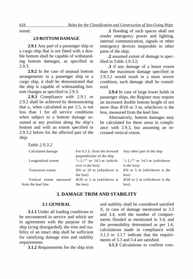
Rules for the Classification and Construction of Sea-Going Ships 618
nored.
2.9 BOTTOM DAMAGE
2.9.1 Any part of a passenger ship or
a cargo ship that is not fitted with a dou-
ble bottom shall be capable of withstand-
ing bottom damages, as specified in
2.9.3.
2.9.2 In the case of unusual bottom
arrangements in a passenger ship or a
cargo ship, it shall be demonstrated that
the ship is capable of withstanding bot-
tom changes as specified in 2.9.3.
2.9.3 Compliance with 2.9.1 or
2.9.2 shall be achieved by demonstrating
that sі, when calculated as per 2.5, is not
less than 1 for all service conditions
when subject to a bottom damage as-
sumed at any position along the ship’s
bottom and with an extent specified in
2.9.3.2 below for the affected part of the
ship:
.1 flooding of such spaces shall not
render emergency power and lighting,
internal communication, signals or other
emergency devices inoperable in other
parts of the ship;
.2 assumed extent of damage is spec-
ified in Table 2.9.3.2;
.3 if any damage of a lesser extent
than the maximum damage specified in
2.9.3.2 would result in a more severe
condition, such damage shall be consid-
ered.
2.9.4 In case of large lower holds in
passenger ships, the Register may require
an increased double bottom height of not
more than В/10 or 3 m, whichever is the
less, measured from the keel line.
Alternatively, bottom damages may
be calculated for these areas in compli-
ance with 2.9.3, but assuming an in-
creased vertical extent.
Table 2.9.3.2
Calculated damage For 0.3 L1 from the forward
perpendicular of the ship
Any other part of the ship
Longitudinal extent 1/3 L12/3 or 14.5 m (which-
ever is the less)
1/3 L12/3 or 14.5 m (whichever
is the less)
Transverse extent В/6 or 10 m (whichever is
the less)
В/6 or 5 m (whichever is the
less)
Vertical extent measured
from the keel line
В/20 or 2 m (whichever is
the less)
В/20 or 2 m (whichever is the
less)
3. DAMAGE TRIM AND STABILITY
3.1 GENERAL
3.1.1 Under all loading conditions to
be encountered in service and which are
in agreements with the purpose of the
ship (icing disregarded), the trim and sta-
bility of an intact ship shall be sufficient
for satisfying damage trim and stability
requirements.
3.1.2 Requirements for the ship trim
and stability shall be considered satisfied
if, in case of damage mentioned in 3.2
and 3.4, with the number of compart-
ments flooded as mentioned in 3.4, and
the permeability determined as per 1.6,
calculations made in compliance with
3.1.3 to 3.1.7 indicate that the require-
ments of 3.3 and 3.4 are satisfied.
3.1.3 Calculations to confirm com-
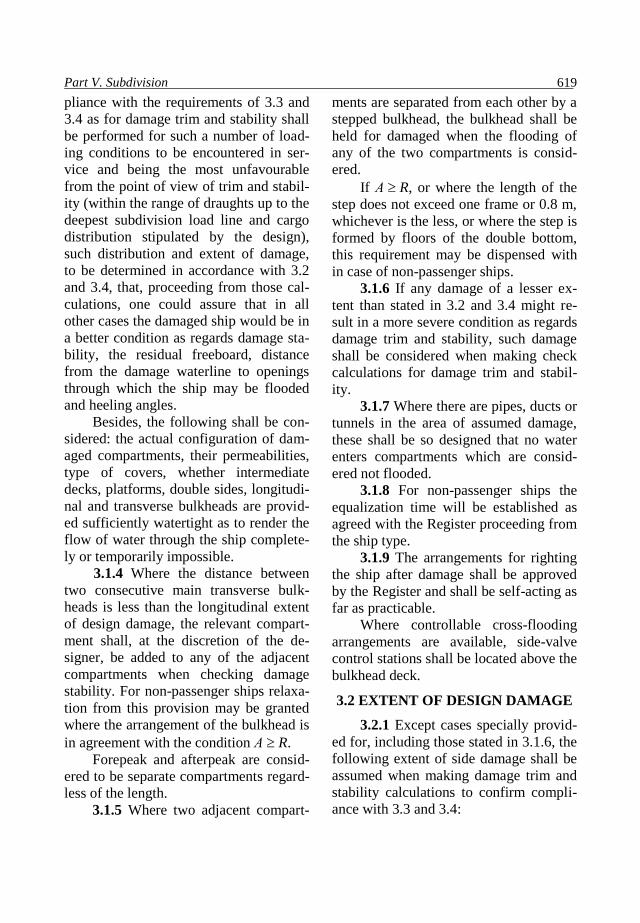
Part V. Subdivision 619
pliance with the requirements of 3.3 and
3.4 as for damage trim and stability shall
be performed for such a number of load-
ing conditions to be encountered in ser-
vice and being the most unfavourable
from the point of view of trim and stabil-
ity (within the range of draughts up to the
deepest subdivision load line and cargo
distribution stipulated by the design),
such distribution and extent of damage,
to be determined in accordance with 3.2
and 3.4, that, proceeding from those cal-
culations, one could assure that in all
other cases the damaged ship would be in
a better condition as regards damage sta-
bility, the residual freeboard, distance
from the damage waterline to openings
through which the ship may be flooded
and heeling angles.
Besides, the following shall be con-
sidered: the actual configuration of dam-
aged compartments, their permeabilities,
type of covers, whether intermediate
decks, platforms, double sides, longitudi-
nal and transverse bulkheads are provid-
ed sufficiently watertight as to render the
flow of water through the ship complete-
ly or temporarily impossible.
3.1.4 Where the distance between
two consecutive main transverse bulk-
heads is less than the longitudinal extent
of design damage, the relevant compart-
ment shall, at the discretion of the de-
signer, be added to any of the adjacent
compartments when checking damage
stability. For non-passenger ships relaxa-
tion from this provision may be granted
where the arrangement of the bulkhead is
in agreement with the condition А R.
Forepeak and afterpeak are consid-
ered to be separate compartments regard-
less of the length.
3.1.5 Where two adjacent compart-
ments are separated from each other by a
stepped bulkhead, the bulkhead shall be
held for damaged when the flooding of
any of the two compartments is consid-
ered.
If А R, or where the length of the
step does not exceed one frame or 0.8 m,
whichever is the less, or where the step is
formed by floors of the double bottom,
this requirement may be dispensed with
in case of non-passenger ships.
3.1.6 If any damage of a lesser ex-
tent than stated in 3.2 and 3.4 might re-
sult in a more severe condition as regards
damage trim and stability, such damage
shall be considered when making check
calculations for damage trim and stabil-
ity.
3.1.7 Where there are pipes, ducts or
tunnels in the area of assumed damage,
these shall be so designed that no water
enters compartments which are consid-
ered not flooded.
3.1.8 For non-passenger ships the
equalization time will be established as
agreed with the Register proceeding from
the ship type.
3.1.9 The arrangements for righting
the ship after damage shall be approved
by the Register and shall be self-acting as
far as practicable.
Where controllable cross-flooding
arrangements are available, side-valve
control stations shall be located above the
bulkhead deck.
3.2 EXTENT OF DESIGN DAMAGE
3.2.1 Except cases specially provid-
ed for, including those stated in 3.1.6, the
following extent of side damage shall be
assumed when making damage trim and
stability calculations to confirm compli-
ance with 3.3 and 3.4:

Rules for the Classification and Construction of Sea-Going Ships 620
.1 longitudinal extent: 1/3 L12/3 or
14.5 m (whichever is the less);
.2 transverse extent measured in-
board from the ship’s side at right angle
to the centreline at the level of the deep-
est subdivision load line: 1/5 of the ship
breadth B or 11.5 m (whichever is the
less);
.3 vertical extent: from the base line
upwards without limit.
3.2.2 The requirements of 3.3 shall
be complied with in case of simultaneous
flooding of all compartments located
forward of collision bulkhead.
3.3 REQUIREMENTS FOR DAM-
AGE TRIM AND STABILITY
CHARACTERISTICS
3.3.1 At the final stage of flooding,
the initial metacentric height of a ship in
the upright condition determined by the
constant displacement method shall not
be less than 0.05 m before appropriate
measures to increase the metacentric
height are taken.
For non-passenger ships, a positive
metacentric height below 0.05 m may be
permitted for the upright condition at the
final stage of flooding as agreed with the
Register.
3.3.2 The angle of heel for unsym-
metrical flooding shall not exceed:
20° before equalization measures
and cross-flooding fittings being used;
12° after equalization measures and
cross-flooding fittings being used.
3.3.3 The static stability curve of a
damaged ship shall have a sufficient
positive lever arm section. At the final
stage of flooding, cross-flooding fittings
disregarded, and after the equalization of
the ship, a length of positive lever arm
curve, flooding angle considered, shall be
ensured not less than 20о. The angle of
submersion of the openings which are not
equipped with watertight or weathertight
covers through which water may spread
to intact compartments may be taken as a
flooding angle.
The maximum lever arm shall be at
least 0.1 m within this length, i.e. within
the heel angle equal to the static one plus
20°.
The positive lever arm section with-
in the said extent shall not be less than
0.0175 mrad.
At the intermediate stages of flood-
ing, the maximum lever arm of the static
stability curve shall be at least 0.05 m,
and the length of its positive section shall
not be less than 7°.
3.3.4 Before, during and after equal-
ization, the damage waterline shall be at
least 0.3 m or 0.1 + (L1 – 10)/150 m
(whichever is the less) below the open-
ings in the bulkheads, decks and sides
through which progressive flooding
could take place.
Such openings include the outlets of
air and vent pipes and those which are
closed by means of weathertight doors
and covers.
These do not necessarily include:
.1 non-opening side and deck scut-
tles;
.2 manholes having covers with
closely space bolts;
.3 cargo tank hatchways in tankers;
.4 remotely controlled sliding doors,
watertight doors with indication systems
(except ships specified in 1.1.1.2, 1.1.1.5,
1.1.1.6 and 1.1.1.8) and access hatches
normally closed at sea;
.5 openings in subdivision bulkheads
intended for the passage of vehicles dur-
ing cargo handling operations which are
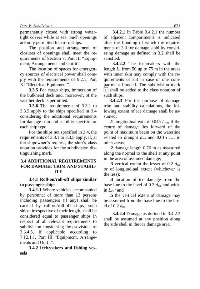
Part V. Subdivision 621
permanently closed with strong water-
tight covers while at sea. Such openings
are only permitted for ro-ro ships.
The position and arrangement of
closures of openings shall meet the re-
quirements of Section 7, Part III “Equip-
ment, Arrangements and Outfit”.
The location of spaces for emergen-
cy sources of electrical power shall com-
ply with the requirements of 9.2.1, Part
XI “Electrical Equipment”.
3.3.5 For cargo ships, immersion of
the bulkhead deck and, moreover, of the
weather deck is permitted.
3.3.6 The requirements of 3.3.1 to
3.3.5 apply to the ships specified in 3.4
considering the additional requirements
for damage trim and stability specific for
each ship type.
For the ships not specified in 3.4, the
requirements of 3.3.1 to 3.3.5 apply, if, at
the shipowner’s request, the ship’s class
notation provides for the subdivision dis-
tinguishing mark.
3.4 ADDITIONAL REQUIREMENTS
FOR DAMAGE TRIM AND STABIL-
ITY
3.4.1 Roll-on/roll-off ships similar
to passenger ships
3.4.1.1 Where vehicles accompanied
by personnel of more than 12 persons
including passengers (if any) shall be
carried by roll-on/roll-off ships, such
ships, irrespective of their length, shall be
considered equal to passenger ships in
respect of all relevant requirements to
subdivision considering the provisions of
3.3.4.5, if applicable according to
7.12.1.1, Part III “Equipment, Arrange-
ments and Outfit”.
3.4.2 Icebreakers and fishing ves-
sels
3.4.2.1 In Table 3.4.2.1 the number
of adjacent compartments is indicated
after the flooding of which the require-
ments of 3.3 for damage stability consid-
ering damage as defined in 3.2 shall be
satisfied.
3.4.2.2 The icebreakers with the
length L1 from 50 up to 75 m in the areas
with inner skin may comply with the re-
quirements of 3.3 in case of one com-
partment flooded. The subdivision mark
1 shall be added to the class notation of
such ships.
3.4.2.3 For the purpose of damage
trim and stability calculations, the fol-
lowing extent of ice damage shall be as-
sumed:
.1 longitudinal extent 0.045 Lice, if the
centre of damage lies forward of the
point of maximum beam on the waterline
related to draught dice and 0.015 Lice in
other areas;
.2 damage length 0.76 m as measured
along the normal to the shell at any point
in the area of assumed damage;
.3 vertical extent the lesser of 0.2 dice
or of longitudinal extent (whichever is
the less);
.4 location of ice damage from the
base line to the level of 0.2 dice and with-
in Lice; and
.5 the vertical extent of damage may
be assumed from the base line to the lev-
el of 0.2 dice.
3.4.2.4 Damage as defined in 3.4.2.3
shall be assumed at any position along
the side shell in the ice damage area.

Rules for the Classification and Construction of Sea-Going Ships 622
Table 3.4.2.1
Type of ship Length L1,
in m
Number of
adjacent
floodable
compartments
Icebreakers 50 and up-
wards 2
Fishing ves-
sels having
over 100 per-
sons on board
100 and up-
wards 1
3.4.3 Special purpose ships
3.4.3.1 Special purpose ships are to
comply with the requirements of Section
2 related to passenger ships and special
personnel shall be considered passengers.
3.4.3.2 The required subdivision in-
dex R shall be calculated as follows:
.1 where the ship is certified to carry
240 persons or more, the required subdi-
vision index shall be assigned as per
2.2.2.3;
.2 where the ship is certified to carry
not more than 60 persons, the required
subdivision index shall be assigned as
0.8R determined in compliance with
2.2.2.3;
.3 for more than 60 (but not more
than 240) persons, the required subdivi-
sion index shall be determined by linear
interpolation between the R-values given
in 3.4.3.2.1 and 3.4.3.2.2.
3.4.4 Tugs, dredgers, salvage ships
and lightships
3.4.4.1 If a single compartment is
flooded, the requirements of 3.3 for dam-
age trim and stability shall be satisfied
for the following types of ships:
tugs having the length L1 ≥ 40 m;
dredgers having the length L1 ≥40 m;
rescue ships and lightships irrespec-
tive of length;
hopper dredgers having the length L1
≥60 m.
3.4.4.2 Bucket dredgers shall com-
ply with the requirements of 3.3 if a sin-
gle compartment is flooded in way of the
bucket opening. The depth of the damage
is assumed equal to 0.76 m.
3.4.4.3 Where hopper dredgers and
hopper barges are concerned, damage
conditions may not be considered corre-
sponding to ship condition after spoil
discharge from one side.
3.4.5 Oil tankers and chemical
tankers
3.4.5.1 The damage trim and stabil-
ity of oil tankers and chemical tankers
shall satisfy the requirements of 3.3 both
for the case of side and bottom damage.
3.4.5.2 Extent of bottom damage:
.1 the longitudinal extent shall be 1/3L1
2/3 or 14.5 m (whichever is the less)
within 0.3L1 from the forward perpendic-
ular and 1/3L12/3 or 5 m (whichever is the
less) through the rest of the ship length;
.2 the transverse extent shall be В/6
or 10 m (whichever is the less) within
0.3L1 from the forward perpendicular and
В/6 or 5 m (whichever is the less)
through the rest of ship length;
.3 the vertical extent measured from
the moulded line of the shell at centreline
shall be В/15 or 6 m (whichever is the
less).
3.4.5.3 In addition to 3.4.5.2, bottom
shell damage shall be considered for oil
tankers with deadweight of 20 000 t and
upwards, having touched the ground, the
extent of damage being as follows:
.1 length of 0.6L1 from the forward
perpendicular for ships having
deadweight of 75 000 t and upwards, and
0.4L1 from the forward perpendicular for
ships with deadweight below 75 000 t;
.2 breadth В/3 anywhere in the bot-

Part V. Subdivision 623
tom.
3.4.5.4 Damage trim and stability
requirements shall be satisfied for the
following locations of side and bottom
damage:
.1 oil tankers:
where the length L1 > 225 m – any-
where the ship length;
where the length 150 < L1 ≤ 225 m –
anywhere in the ship length except for
the engine room when this is located aft.
In this case, the engine room shall be
considered a separate floodable com-
partment;
where the length L1 150 m – any-
where in the ship length between consec-
utive transverse bulkheads except for the
engine room;
where the substances of the Catego-
ry Y are carried as per the provisions of
Annex II to MARPOL 73/78, as for
chemical tankers 3;
.2 chemical tankers:
chemical tanker 1 – anywhere along
the ship length;
chemical tanker 2 having the length
L1 > 150 m – anywhere along the ship
length;
chemical tanker 2 having the length
L1 150 m – anywhere in the ship length
except for the engine room where this is
located aft. In this case, the engine room
shall be considered a separate floodable
compartment;
chemical tanker 3 having the length
L1 > 225 m – anywhere along the ship
length;
chemical tanker 3 having the length
L1 = 125 – 225 m – anywhere in the ship
length except for the engine room where
this is located aft. In this case, the engine
room shall be considered a separate
floodable compartment;
chemical tanker 3 having the length
L1 < 125 m – anywhere along the ship
length except for the engine room where
this is located aft. Nevertheless, damage
trim and stability calculations for the
conditions of the engine room shall be
submitted to the Register for review.
3.4.5.5 Ships which do not comply
with the requirements for damage trim
and stability when their engine room is
flooded as provided by 3.4.5.4.1 and
3.4.5.4.2, are not assigned a subdivision
distinguishing mark in their class nota-
tion.
3.4.5.6 At the final stage of unsym-
metrical flooding before equalization
measures and cross-flooding fittings be-
ing used, the angle of heel shall not ex-
ceed 25° (or 30°, where the bulkhead
deck is not immersed). After equalization
measures, the heeling angle shall not ex-
ceed 17°.
3.4.6 Gas carriers
For gas carriers, the requirements of
3.4.5 apply except for the following de-
tails:
.1 damage trim and stability re-
quirements shall be satisfied when side
and bottom damage is sustained as stated
below:
gas carriers 1G – anywhere along
the ship length;
gas carriers 2G having the length
L1 > 150 m – anywhere along the ship
length;
gas carriers 2G having the length
L1 150 m – anywhere along the ship
length except the engine room where this
is located aft. In this case the engine
room shall be considered a separate
floodable compartment;
gas carriers 2PG – anywhere in the
ship length between subdivision bulk-

Rules for the Classification and Construction of Sea-Going Ships 624
heads;
gas carriers 3G having the length
L1 125 m – anywhere in the ship length
between subdivision bulkheads;
gas carriers 3G having the length
L1 < 125 m – anywhere in the ship length
between subdivision bulkheads except
the engine room where this is located aft.
However, damage trim and stability cal-
culations for the case of the engine room
being flooded shall be submitted for the
consideration of the Register. No subdi-
vision distinguishing mark shall be intro-
duced in the class notation if damage trim
and stability requirements are not met;
.2 the vertical extent of a bottom
damage shall be assumed equal to В/15
or 2 m, whichever is the less.
3.4.7 Drilling ships
With any single compartment flood-
ed, drilling ships shall comply with the
requirements of 3.3, unless more strin-
gent requirements are put forward by the
shipowner.
Drilling ships shall have sufficient
reserve of damage stability to withstand
the wind heeling moment produced by
wind with a speed of 25.8 m/s (50 knots)
acting from any direction. Under these
conditions the final waterline after flood-
ing shall be located below the lower edge
of any opening through which the intact
compartments may be flooded by the sea.
3.4.8 Ships intended for the car-
riage of radioactive agents
Damage trim and stability of ships
intended for the carriage of packaged
irradiated nuclear fuel, plutonium and
high level radioactive wastes with the
total radioactivity below 4000 TBq shall
in each case be specially considered by
the Register.
The requirements for the damage
trim and stability of ships carrying pack-
aged irradiated nuclear fuel or high level
radioactive wastes with the total radioac-
tivity below 6102 TBq or plutonium
with the total radioactivity below
5102 TBq, shall be met for the case of
specified damage anywhere along the
ship length between the consecutive
transverse bulkheads.
The requirements for the damage
trim and stability of ships carrying pack-
aged irradiated nuclear fuel or high level
radioactive wastes with the total radioac-
tivity above 6102 TBq or plutonium
with the total radioactivity 5102 TBq
and above shall be met for the case of
specified damage anywhere along the
ship length.
As agreed with the Register the pos-
sible probability estimation of the ship
subdivision may be considered being an
alternative to the requirements indicated.
For ships carrying radioactive agents
the required subdivision index R shall be
determined by the Register. In any case,
for ships carrying radioactive agents with
the total radioactivity above 6102 TBq
or plutonium with the total radioactivity
above 5102 TBq, the required subdivi-
sion index shall be equal to
R = R0+ 0.2 (1- R0), but not less than
0.6,
where R0 is the value of R calculated as per
2.2.1.1 and 2.2.2.2.
For ships where Ls < 80 m, the value
of required subdivision index R shall be
determined by the formula
R =1-[1/(1+ 0.8 R 0 /(1- R0)], (3.4.8)
where R0 is the value of R calculated in

Part V. Subdivision 625
compliance with 2.2.1.1.
3.4.9 Supply vessels 3.4.9.1 The requirements of the pre-
sent Chapter apply to all supply vessels
having the length L1 = 100 m and less.
The subdivision and damage stabil-
ity of supply vessels having a length over
100 m shall in each case be specially
considered by the Register.
3.4.9.2 The extent of damage
In damage trim and stability calcula-
tions the damage of extent shall be as
follows:
.1 longitudinal extent shall be 1/3
L12/3 for the ships with length L1 80 m;
for the ships with length L1 > 43 m, the
longitudinal extent shall be 3 m + 0.03L1, and for the ships with length L1 43 m,
the longitudinal extent shall be 0.10L1;
.2 transverse extent of damage shall
be assumed for as В/20 (but not less than
0.76 m) with length L1 80 m, measured
inboard from the side of the ship at right
angle to the centreline at the level of the
summer load waterline;
.3 vertical extent: from the underside
of the cargo deck, or the continuation
thereof, for the full depth of the ship.
3.4.9.3 A transverse watertight
bulkhead extending from the ship’s side
to a distance inboard as specified in
3.4.9.2.2, or more measured at right angle
to the centreline at the level of the sum-
mer load line joining longitudinal water-
tight bulkhead for the purpose of the
damage trim and stability calculations.
3.4.9.4 Where a transverse water-
tight bulkhead is located within the
transverse extent of assumed damage and
is stepped in way of a double bottom or
side tank by more than 3.0 m, the double
bottom or side tanks adjacent to the
stepped portion of the transverse water-
tight bulkhead shall be considered as
damaged.
3.4.9.5 At the final stage of unsym-
metrical flooding the angle of heel shall
not exceed 15° (or 17°, if no deck im-
mersion occurs) before equalization
measures are taken and cross-flooding
fittings are used.
3.4.9.6 Number of floodable com-
partments
The damage stability requirements
of 3.3 shall be met in the case of single
compartment flooding proceeding from
the extent of damage stated under 3.2.1.1,
3.2.1.3 and 3.4.9.2.
3.4.9.7 Ships complying with the re-
quirements of 3.4.9.2 only, will receive
no subdivision distinguishing mark in the
class notation.
3.4.9.8 If preferred by the shipown-
er, a supply vessel may receive a subdivi-
sion distinguishing mark with the number
of floodable compartments indicated in
the class notation. In this case, the trans-
verse extent of damage shall be assumed
as per 3.2.1.2. The number of compart-
ments at the flooding of which the dam-
age trim and stability requirements are to
be met shall be determined by the ship-
owner.
3.4.10 Ships with ice strengthening
marks of categories Ісе4, Ісе5 and Ісе6
3.4.10.1 The requirements of this
paragraph apply to all ice strengthened
ships of categories Ісе4, Ісе5 and Ісе6.
The damage trim and stability require-
ments shall be met as far as the draught
dice is concerned except for the require-
ment of 3.4.10.2.
3.4.10.2 Where the extent of damage
is in compliance with 3.2, within range of
the summer load line draught assigned to
the ship the damage trim and stability

Rules for the Classification and Construction of Sea-Going Ships 626
requirements of 3.3 shall be met if a sin-
gle compartment is flooded in ships hav-
ing the following distinguishing marks in
the class notation:
ice category mark Ісе 6 irrespective
of ship length;
ice category mark Ісе 5 with the
ship length L1 120 m.
The subdivision distinguishing mark
1 shall be introduced in the class nota-
tion of such ships.
3.4.10.3 Ships with the ice strength-
ening marks for categories Ісе 4, Ісе 5
and Ісе 6 (irrespective of their length)
shall comply with the requirements of 3.3
with relevant ice damage stated in
3.4.10.4 and the number of floodable
compartments given in 3.4.10.5.
Where compliance with the re-
quirements of other Sections of this Part
also testifies to 3.4.10 being complied
with, no additional damage trim and sta-
bility calculations need be made for dam-
age conditions mentioned under 3.4.10.4
and 3.4.10.5
3.4.10.4 For the purpose of damage
trim and stability calculations, the fol-
lowing extent of ice damage shall be as-
sumed:
.1 longitudinal extent 0.045Lice, if
the centre of damage lies within 0.4Lice
from the forward perpendicular, and
0.015Lice in other areas;
.2 damage depth 0.76 m as measured
along the normal to the shell at any point
in the area of assumed damage;
.3 vertical extent 0.2dice;
.4 location of damage from the base
line to the level of 1.2dice within Lice.
3.4.10.5 When performing damage
trim and stability calculations, the num-
ber of floodable compartments shall be
determined proceeding from the location
of the assumed ice damage given in Ta-
ble 3.4.10.5.
3.4.10.6 In all cases, irrespective of
the requirements stated in items 11 and
12 of Table 3.4.10.5, the calculations of
damage trim and stability for the case of
the engine room being flooded shall be
submitted for the consideration of the
Register.
3.4.10.7 For oil tankers, chemical
tankers 2 and 3, gas carriers 2G and 3G
below or equal to 150 m in length, the
necessity of considering a simultaneous
flooding of the engine room and an adja-
cent compartment shall be specially con-
sidered by the Register.
Table 3.4.10.5 Location of assumed ice damage of the ships subject to the
purpose and ice strengthening category
No. Purpose of ship and/or ice strengthening
category
Location of ice damage specified in
3.4.10.4
1 2 3
1 Ice-strengthened ships of Ісе6 category,
except fishing vessels Anywhere in the ice damage area
2 Passenger ships allowed to carry over 400
passengers including the crew Ditto
3 Special purpose ships allowed to carry over
400 passengers including the crew Ditto
4 Ships intended for the carriage of radioac-
tive agents Ditto

Part V. Subdivision 627
End of Table 3.4.10.5
1 2 3
5 Chemical tankers Ditto
6 Oil tankers Ditto
7 Gas carriers Ditto
8 Drilling ships Ditto
9 Ice-strengthened salvage ships with ice cat-
egories Ісе5 and Ісе6 Ditto
10 Ice-strengthened fishing vessels and refrig-
erated fish carriers with ice categories Ісе6
Between watertight bulkheads, platforms,
decks and plating1
11
Ice-strengthened ships with ice category
Ісе5 not mentioned in 2 to 9
Between watertight bulkheads, platforms,
decks and plating1. With the hull length
L1 < 100 m it is permitted not to comply
with the requirements for damage trim and
stability where engine room located aft is
flooded in case of ice damage. The same
refers to the flooding of engine rooms of
tugs less than 40 m in length irrespective of
the engine room location.
12 Ice-strengthened ships with ice category
Ісе4, not mentioned in 2 to 9
Between watertight bulkheads, platforms,
decks and plating1. With the hull length
L1 < 125 m it is permitted not to comply
with the requirements for damage trim and
stability where engine room located aft is
flooded in case of ice damage. The same
refers to the flooding of engine rooms of
tugs less than 40 m in length irrespective of
the engine room location.
1Where the distance between two consecutive watertight structures is less than the extent
of damage, relative adjacent compartments shall be considered a single floodable compartment
when checking damage trim and stability.
3.4.10.8 Ships conforming with the
requirements of 3.4.10.3 to 3.4.10.7 only
will receive no subdivision distinguishing
mark in the class notation.
3.4.11 Bulk carriers, ore carriers
and combination carriers
3.4.11.1 Bulk carriers having the
length L1 150 m and upwards, which car-
ry solid bulk cargoes with density
1000 kg/m3 and above, shall meet the
requirements of 4.4 at flooding of any
cargo hold bounded by the side shell only
or being double side skin construction
with the width less than В/5 or 11.5 m
(whichever is the less) in all cases of
draught up to the summer load line.
3.4.11.2 When calculating damage
stability the following permeabilities
shall be taken:
0.90 for loaded holds;
0.95 for empty holds.
Ships assigned with the reduced
freeboard as per Section 4 are regarded of
satisfying the requirements of 3.4.11.1.
Information on compliance with
these requirements shall be included in

Rules for the Classification and Construction of Sea-Going Ships 628
the Information on Stability and Strength
for the Ship Loaded with Solid Bulk Car-
goes other than Grain as required by
1.4.9.7, Part II “Hull”.
3.4.11.3 Ships are fitted with
flooding detection sensors as follows:
.1 in each cargo hold, giving audible
and visual alarms (one when the water
level above the inner bottom in the hold
reaches a height of 0.5 m high, and an-
other at a height not less than 15 per cent
of the cargo hold depth but not more than
2.0 m above the inner bottom); it is al-
lowed to use one detector instead of two
provided its design allows to give alarm
at both levels of hold flooding. The de-
tectors are fitted in the aft end of the car-
go hold as close to the centreline, as prac-
ticable, or above its lowest part where the
inner bottom is not parallel to the de-
signed waterline.
If detectors cannot be placed within
a distance equal to one corrugation space
or one bulkhead vertical stiffener space
from the centreline, they shall be located
at both the port and starboard sides of the
cargo hold;
.2 in any ballast tank forward of the
collision bulkhead required in 1.1.6, Part
II “Hull” giving an audible and visual
alarm when the liquid in the tank reaches
a level not exceeding 10 per cent of tank
capacity;
.3 in any dry or void space other
than a chain cable locker, any part of
which extends forward of the foremost
cargo hold, giving an audible and visual
alarm at a water level of 0.1 m above the
deck. Such alarms need not be provided
in enclosed spaces, the volume of which
does not exceed 0.1 per cent of the ship’s
maximum displacement volume.
Detectors in cargo holds shall be
protected by a robust construction from
damage by cargoes or mechanical han-
dling equipment associated with bulk
carrier operations.
3.4.11.4 On ships the Flooding De-
tection System Manual shall be provided,
which includes, as a minimum:
.1 the flooding detection system
specification, including a list of proce-
dures for checking the operability, as far
as practicable, of each element at any
stage of the ship service;
.2 the Type Approval Certificate is-
sued for the flooding detection system;
.3 the single-line diagram of the
flooding detection system with the loca-
tion of equipment indicated in the ship’s
general arrangement plan;
.4 the instructions indicating the lo-
cation, securing, protection and testing of
the flooding detection system equipment;
.5 list of cargoes in which 50 per
cent mixture with seawater detectors pro-
tected by guard remain operable;
.6 the procedures to be followed in
case of failure of the flooding detection
system;
.7 the maintenance requirements for
the flooding detection system equipment.
The Manual shall be in the working
language of the ship officers, as well as
in English.
3.4.11.5 The flooding detection sys-
tem shall meet the requirements of 7.10,
Part XI “Electrical Equipment”.
3.4.12 Berth-connected ships
3.4.12.1 The requirements stated in
3.3 shall be complied with in the case of
any single flooded compartment lying
along the ship periphery and having the
length not less than the length of assumed
damage given in 3.4.12.2.2.
3.4.12.2 For the purpose of damage

Part V. Subdivision 629
trim and stability calculations, the fol-
lowing extent of damage shall be as-
sumed:
.1 transverse extent measured from
the inner skin at right angles to the cen-
treline on the level of the deepest water-
line permitted by the load line – 0.76 m;
.2 longitudinal extent – 1/6L12/3 or
7.2 m (whichever is the less);
.3 vertical extent – as per 3.2.1.3;
3.4.12.3 No subdivision distinguish-
ing mark will be introduced in the class
notation of berth-connected ships which
comply solely with the requirements of
3.4.12 and for which regard to 3.4.12.2
shall be taken.
3.4.13.4 If the depth of waters on
which the berth-connected ship floats is
such that the lower-most deck accessible
to passengers cannot be immersed not to
mention capsizing of the ship, the re-
quirements of this Section may be
waived.
3.4.13 Cargo ships having the
length less than 100 m other than bulk
carriers
3.4.13.1 Single hold cargo ships
other than bulk carriers shall comply with
the present requirements not later than
the date of the first intermediate or re-
newal survey of the ship, whichever
comes first, but, anyway, not later than
31 December 2009.
3.4.13.2 Ships having the length L1
less than 80 m, or, if constructed before
1998 – less than 100 m, and a single car-
go hold below the freeboard deck or car-
go holds below the freeboard deck which
are not separated by at least one bulkhead
made watertight up to that deck, shall be
fitted in such space or spaces with flood-
ing detection sensors, which give an au-
dible and visual alarm at the navigation
bridge when the water level above the
inner bottom in the cargo hold reaches a
height of not less than 0.3 m, and another
when such level reaches not more than 15
per cent of the mean depth of the cargo
hold.
3.4.13.3 Flooding detection sensors
shall be fitted at the aft end of the hold,
or above its lowest part where the inner
bottom is not parallel to the designed wa-
terline. If sensors cannot be placed within
a distance equal to one corrugation space
or one bulkhead vertical stiffener space
from the centreline, they shall be located
at both sides of the cargo hold. Where
webs or partial watertight bulkheads are
fitted above the inner bottom, the Regis-
ter may require the fitting of additional
sensors. It is allowed to use one sensor
vertically instead of two provided its de-
sign allows giving alarm at both levels of
hold flooding.
3.4.13.4 The flooding detection
sensors need not be fitted in ships com-
plying with the requirements of 3.4.11.3,
or in ships having watertight side com-
partments each side of the cargo hold
length extending vertically at least from
inner bottom to freeboard deck.
3.4.13.5 The flooding detection
system shall comply with the require-
ments of 7.10, Part XI “Electrical
Equipment”.
3.4.14 Ro-ro passenger ships
3.4.14.1 Ro-ro passenger ship stability
required at the final stage after the dam-
age caused by collision and after equali-
zation shall comply with the require-
ments of this paragraph in addition to
3.4.1.
3.4.14.2 The existing ro-ro passenger
ships shall comply with the requirements
of this paragraph within the terms as pro-

Rules for the Classification and Construction of Sea-Going Ships 630
vided by Article 7 of the Directive
2003/25/EC of the European Parliament
and of the Council of 14 April 2003 con-
sidering amendments and additions as per
the Commission Directive 2005/12/EC of
18 February 2005 of the European Par-
liament and of the Council on specific
stability requirements for ro-ro passenger
ships.
3.4.14.3 In addition to 1.2.1 the fol-
lowing definitions and explanations have
been adopted in this paragraph:
Drainage system means a system
providing removal of seawater from the
ro-ro deck that comes due to the stormy
conditions or damage to a ship.
Residual freeboard (fr) is the min-
imum distance between the damaged ro-
ro deck and the final waterline (after
equalisation measures if any have been
taken) in way of the assumed damage
after examining all possible damage sce-
narios in determining, without taking into
account the additional effect of the sea
water accumulated on the damaged ro-ro
deck.
Significant wave height (hS) is
the average height of the highest wave
heights measured between the wave hol-
low and wave top. The figures of signifi-
cant wave heights shall be those which
are not exceeded by a probability of more
than 10 % on a yearly basis.
Significant wave height (hS) shall be
used in determining the height of water
on ro-ro deck (hw) when applying the
specific stability requirements*.
Ro-ro deck means a deck in closed
or open ro-ro cargo spaces or special ro-
ro spaces as defined in 1.5.4.3 ÷ 1.5.4.4
and 1.5.9, Part VI “Fire Protection” of
the Rules.
Ro-ro passenger ship means a
ship carrying more than 12 passengers,
having closed or open ro-ro cargo spaces
or special category spaces as defined in
1.5.4.3 ÷ 1.5.4.4 and 1.5.9, Part VI “Fire
Protection”.
Ferryboats that are via ferry crossing
engaged on regular carriages of passen-
gers and carriage of vehicles with oil in
tanks on open and/or closed deck and/or
railway rolling stock with horizontal
loading and discharging shall be also re-
ferred to ro-ro passenger ships.
Regular service means a series of
ro-ro passenger ship crossings serving
traffic between the same two or more
ports, which is operated either
according to a published timetable; or
with crossings so regular or frequent
that they constitute a recognisable sys-
tematic series.
Specific stabil i ty requirements
means the requirements based on the
method**, calculating the height of water
on the ro-ro deck after the damage under
the two basic parameters: residual free-
board (fr) and significant wave height on
the territory of the ship (hS).
SOLAS Stabil i ty Standard
means the requirements providing a level
of safety equivalent to the specific stabil-
ity requirements established for ships
operating in sea areas where the signifi-
cant wave height (hS) is equal to or less
than 1.5 m.
Stabil i ty standard for ro -ro
passenger ships in damaged con-
dit ion means the requirements to take
into account the effect of water accumu-
lation on the ro-ro deck and to enable the
ship to survive in more severe states than
the SOLAS standard, up to 4 m signifi-
cant wave heights.

Part V. Subdivision 631
Stockholm Agreement means the
Agreement concluded at Stockholm on
28 February 1996 in pursuance of SO-
LAS 95 Conference Resolution 14 “Re-
gional agreements on specific stability
requirements for ro-ro passenger ships”,
adopted on 29 November 1995.
Freeing ports means scuppers
providing to free the water accumulated
due to stormy conditions or damage of
the ship from the ro-ro deck directly
overboard.
* When determining significant wave
height (hS), the wave heights given on the
maps or list of sea areas are to be used.
In compliance with clause 21, Articles
4 and 5 of the Directive 2003/25/EC of
the European Parliament and of the
Council of 14 April 2003 considering
amendments and additions as per the
Commission Directive 2005/12/EC of 18
February 2005 of the European Parlia-
ment and of the Council, each Member
State should determine and update, if
necessary, the sea areas under their juris-
diction, of the significant wave height
(hS), delimiting the zones for the all-year-
round and, where appropriate, restricted
periodical operation of ro-ro passenger
ships.
Significant wave heights (hS) for sea-
sonal operation shall be determined by
the host State Administration in agree-
ment with the other country whose port is
included in the ship’s route.
** Refer to Annexes to the Stockholm
Agreement and Directive 2003/25/EC of
the European Parliament and of the
Council of 14 April 2003 considering
amendments and additions as per the
Commission Directive 2005/12/EC of 18
February 2005 of the European Parlia-
ment and of the Council on specific sta-
bility requirements for ro-ro passenger
ships.
3.4.14.4 Ro-ro passenger ship’s stabil-
ity in the final condition after damage
due to collision and after equalization
shall be determined considering the effect
of water that may be accumulated on the
first ro-ro deck or special cargo space
above the waterline and to enable the
ship to survive in more severe states than
the SOLAS standard, up to 4 m signifi-
cant wave heights. 3.4.14.5 The stability required in the
final condition after damage, and after
equalization shall be determined as fol-
lows as per the SOLAS stability stand-
ard:
.1 The positive residual righting lever
curve shall have a minimum range of 15°
beyond the angle of equilibrium.
This range may be reduced to a mini-
mum of 10°, in the case where the area
under the righting lever curve is that
specified in paragraph 3.4.14.4.3, multi-
plied by the ratio “15/range”, where the
range is expressed in degrees.
.2 The area under the righting lever
curve shall be at least 0.015 m·rad,
measured from the angle of equilibrium
to the lesser of:
.2.1 the angle at which progressive
flooding occurs; or
.2.2 22° (measured from the upright)
in the case of one-compartment flooding,
or 27° (measured from the upright) in the
case of the simultaneous flooding of two
adjacent compartments.
.3 A residual righting lever GZ, in m,
is to be calculated by the formula:
GZ = (heeling moment/displacement) +
0.04 (3.4.14.4.4),

Rules for the Classification and Construction of Sea-Going Ships 632
shall be within the range of positive
stability, taking into account the greatest
of the following heeling moments:
.3.1 the crowding of all passengers
towards one side;
.3.2 the launching of all fully loaded
davit-launched survival craft on one side; .3.3 due to wind pressure.
However, in no case is this righting
lever to be less than 0.10 m.
.4 For the purpose of calculating the
heeling moments given in paragraph
3.4.14.4.4, the following assumptions
shall be made: .4.1 moments due to crowding of
passengers:
- four persons per m2;
- a mass of 75 kg per each passen-
ger;
- passengers are distributed on avail-
able deck areas towards one side of the
ship on the decks where muster stations
are located and in such a way that they
produce the most adverse heeling mo-
ment.
.4.2 moments due to launching of
all fully loaded davit-launched survival
craft on one side of the ship:
.4.2.1 all lifeboats and rescue boats
fitted on the side to which the ship has
heeled after having sustained damage
shall be assumed to be swung out fully
loaded and ready for lowering;
.4.2.2 for lifeboats which are ar-
ranged to be launched fully loaded from
the stowed position, the maximum heel-
ing moment during launching shall be
taken;
.4.2.3 a fully loaded davit-launched
liferaft attached to each davit on the side
to which the ship has heeled after having
sustained damage shall be assumed to be
swung out ready for lowering;
.4.2.4 persons not in the life-saving
appliances which are swung out shall not
provide either additional heeling or right-
ing moment;
.4.2.5 lifesaving appliances on the
side of the ship opposite to the side to
which the ship has heeled shall be as-
sumed to be in a stowed position.
.4.3 moments due to wind pressure:
a wind pressure of 120 Pa (120 N/m2),
to be applied,
where:
- the area applicable shall be the pro-
jected lateral area of the ship above the
waterline corresponding to the intact
condition;
- the moment arm shall be the vertical
distance from a point at one half of the
mean draught corresponding to the intact
condition to the centre of gravity of the
lateral area.
3.4.14.6 The conditions for stability
required by SOLAS stability standard,
refer to paragraph 3.4.14.5, are to be
complied with considering the effect of
sea water that may be accumulated on
the first ro-ro deck or special cargo space
(hereinafter referred to “damaged ro-ro
deck”) above the deepest subdivision
load line in a way of damage.
3.4.14.7 The accumulated water is
added as a liquid load with one common
surface inside all compartments which
are assumed flooded on the damaged ro-
ro deck.
The height of water (hw) on deck is
dependent on the residual freeboard (fr)
after damage, and is measured in way of
the damage (refer to Fig. 3.4.14.7-1).
No account should be taken of the ef-
fect of the hypothetical volume of water
assumed to have accumulated on the

Part V. Subdivision 633
damaged ro-ro deck when calculating the
residual freeboard (fr).
The amount of assumed accumulated
sea water shall be calculated on the basis
of a water surface having a fixed height
above:
the lowest point of the ro-ro deck
edge of the damaged compartment, if the
edge of the damaged ro-ro deck is not
submerged (refer to Fig. 3.4.14.7-2 а));
or
if the ro-ro deck edge of the damaged
compartment is submerged, then the cal-
culation is based on a fixed height above
the still water surface at all heel and/or
trim angles (refer to Fig 3.4.14.7-2 b)).
If fr ≥ 2.0 m, no water is assumed on
the damaged ro-ro deck.
If fr ≤ 0.3 m, the height hw on the
damaged ro-ro deck is assumed to be 0.5
m.
If 0.3 m ≤ fr < 2.0 m, the height hw
on the damaged ro-ro deck shall be ob-
tained by linear interpolation.
3.4.14.8 When a high efficiency
drainage system is installed, the reduce of
the permissible height (hw) of water sur-
face may be allowed.
Note: Means for drainage of water can
only be considered as effective if these
means are of a capacity to prevent large
amounts of water from accumulating on
the damaged ro-ro deck i.e. many thou-
sands of tonnes per hour.
* Damage provided by SOLAS Stability
Standard.
А-А (Scheme determining the size of a
freeboard)
Fig. 3.4.14.7-1
a)
b)
Fig. 3.4.14.7-2
3.4.14.9 The height of accumulated
water (hw), permitted on the damaged ro-
ro deck as per 3.4.14.6 ÷ 3.4.14.7, may
be reduced for ships in geographically
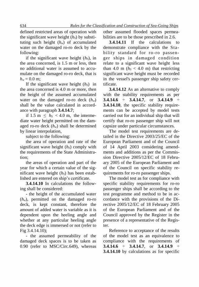
Rules for the Classification and Construction of Sea-Going Ships 634
defined restricted areas of operation with
the significant wave height (hS) by substi-
tuting such height (hw) of accumulated
water on the damaged ro-ro deck by the
following:
if the significant wave height (hS), in
the area concerned, is 1.5 m or less, then
no additional water is assumed to accu-
mulate on the damaged ro-ro deck, that is
hw = 0.0 m;
If the significant wave height (hS) in
the area concerned is 4.0 m or more, then
the height of the assumed accumulated
water on the damaged ro-ro deck (hw)
shall be the value calculated in accord-
ance with paragraph 3.4.14.7;
if 1.5 m ≤ hS < 4.0 m, the interme-
diate water height permitted on the dam-
aged ro-ro deck (hw) shall be determined
by linear interpolation,
subject to the following:
the area of operation and rate of the
significant wave height (hS) comply with
the requirements of the State Administra-
tion;
the areas of operation and part of the
year for which a certain value of the sig-
nificant wave height (hS) has been estab-
lished are entered on ship’s certificate.
3.4.14.10 In calculations the follow-
ing shall be considered:
- the height of the accumulated water
(hw), permitted on the damaged ro-ro
deck, is kept constant, therefore the
amount of added water is variable as it is
dependent upon the heeling angle and
whether at any particular heeling angle
the deck edge is immersed or not (refer to
Fig 3.4.14.10);
- the assumed permeability of the
damaged deck spaces is to be taken as
0.90 (refer to MSC/Circ.649), whereas
other assumed flooded spaces permea-
bilities are to be those prescribed in 2.6.
3.4.14.11 If the calculations to
demonstrate compliance with the Sta-
bil i ty standard for ro -ro passen-
ger ships in damaged condition
relate to a significant wave height less
than 4.0 m (hS < 4.0 m) that restricting
significant wave height must be recorded
in the vessel's passenger ship safety cer-
tificate.
3.4.14.12 As an alternative to comply
with the stability requirements as per
3.4.14.6 ÷ 3.4.14.7, or 3.4.14.9 ÷
3.4.14.10, the specific stability require-
ments can be accepted by model tests
carried out for an individual ship that will
certify that ro-ro passenger ship will not
capsize under particular circumstances.
The model test requirements are de-
tailed in the Directive 2003/25/EC of the
European Parliament and of the Council
of 14 April 2003 considering amend-
ments and additions as per the Commis-
sion Directive 2005/12/EC of 18 Febru-
ary 2005 of the European Parliament and
of the Council on specific stability re-
quirements for ro-ro passenger ships.
The model test as for compliance with
specific stability requirements for ro-ro
passenger ships shall be according to the
test programme and method to be in ac-
cordance with the provisions of the Di-
rective 2005/12/EC of 18 February 2005
of the European Parliament and of the
Council approved by the Register in the
presence of a representative of the Regis-
ter.
Reference to acceptance of the results
of the model test as an equivalence to
compliance with the requirements of
3.4.14.6 ÷ 3.4.14.7, or 3.4.14.9 ÷
3.4.14.10 by calculations as for specific

Part V. Subdivision 635
stability requirements of ro-ro passenger
ships, and the significant wave height
(hS) used in model tests shall be entered
on the ship’s certificate.
Fig. 3.4.14.10
3.4.14.13 SOLAS stability standard
(refer to 3.4.14.3), limiting operational
curve(s) KG or GM, may not remain ap-
plicable in cases where "water on deck"
is assumed under the terms of this para-
graph and it may be necessary to deter-
mine revised limiting curve(s) which take
into account the effects of this added wa-
ter.
To this effect sufficient calculations
corresponding to an adequate number of
operational draughts and trims must be
carried out.
Note: Revised limiting operational
KG/GM curves may be derived by itera-
tion, whereby the minimum excess GM
resulting from damage stability calcula-
tions with water on deck is added to the
input KG (or deducted from the GM)
used to determine the damaged free-
boards (fr), upon which the quantities of
water on deck are based, this process be-
ing repeated until the excess GM be-
comes negligible.
It is anticipated that operators would
begin such an iteration with the maxi-
mum KG/minimum GM which could rea-
sonably be sustained in service and
would seek to manipulate the resulting
ro-ro deck bulkhead arrangement to min-
imize the excess GM derived from dam-
age stability calculations with water on
deck.
3.4.14.14 For assessing the effect of
the volume of the assumed accumulated
sea water on the damaged ro-ro deck as
per 3.4.14.6 ÷ 3.4.14.7 or 3.4.14.9 ÷
3.4.14.10, the following conditions shall
be considered:
- a transverse or longitudinal bulkhead
shall be considered intact in the event of
side collision damage if all parts of it lie
inboard of vertical surfaces on both sides
of the ship, which are situated at a dis-
tance from the shell plating equal to 1/5 В
and measured at right angles to the cen-
treline at the level of the deepest subdivi-
sion load line;
- in cases where the ship’s hull is
structurally partly widened for compli-
ance with the stability requirements, the
resulting increase of the value 1/5 В shall
Rules for the Classification and Construction of Sea-Going Ships 636
not cause the relocation of any existing
structural parts or any existing penetra-
tions of the main transverse watertight
bulkheads below the bulkhead ro-ro
deck, piping systems, etc., which were
acceptable prior to widening.
3.4.14.15. The tightness of transverse
or longitudinal bulkheads which are tak-
en into account as effective to confine the
assumed accumulated sea water in the
compartment(s) concerned in the dam-
aged ro-ro deck, shall be commensurate
with drainage system, and shall withstand
hydrostatic pressure in accordance with
the results of the damage calculation.
Such bulkheads/barriers shall be not
less than 4 meters, if the water height on
the damaged ro-ro deck is hw > 0.5 m.
In other cases, the height of a bulk-
head/barrier shall be calculated by the
following formula:
Bh = 8×hw (3.4.14.15.).
where:
Bh is a height of a bulkhead/barrier, in
m;
hw is the water height, in m.
In no case is the height of the bulk-
head/barrier to be less than 2.2 m.
However, in case of a ship with hang-
ing car decks, the minimum height of the
bulkhead/barrier shall be not less than the
height to the underside of the hanging
deck when it its lowered position. It
should be noted that any gaps between
the top edge of the bulkhead/barrier and
the underside of the plating must be
"plated-in" in the transverse or longitudi-
nal direction as appropriate.
Bulkheads/barriers with a height less
than that specified above, and special
arrangements, such as full-width hanging
decks and wide side casings, may be ac-
cepted if model tests are carried out in
accordance with 3.4.14.12, to confirm
that the alternative design ensures to pre-
vent progressive flooding within the re-
quired stability range (refer to
3.4.14.4.5).
Note: This range may be reduced to
10° provided the corresponding area un-
der the curve complies with the require-
ments of 3.4.14.4.5.
3.4.14.16 Transverse or longitudinal
bulkheads/barriers in the lower part up to
the level provided for hw, which are fitted
and taken into account to confine the
movement of assumed accumulated wa-
ter on the damaged ro-ro deck need not
be strictly "watertight" subject to the
drainage provisions being capable of pre-
venting an accumulation of water on the
"other side" of the bulkhead/barrier.
In such cases where scuppers become
inoperative as a result of a loss of posi-
tive difference of water levels other
means of passive drainage must be pro-
vided.
3.4.14.17 The effect of the volume of
the assumed accumulated sea water need
not be taken into account for any com-
partment of the damaged ro-ro deck, pro-
vided that such a compartment has on
each side of the deck freeing ports evenly
distributed along the sides of the com-
partment complying with the following
formula:
A ≥ 0.3· l (3.4.14.17).
where:
A is the total area of freeing ports on
each side of the ro-ro deck of the ship’s
compartment, m2;
l is the length of the compartment, in
m.
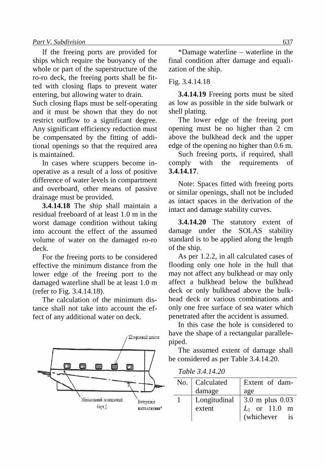
Part V. Subdivision 637
If the freeing ports are provided for
ships which require the buoyancy of the
whole or part of the superstructure of the
ro-ro deck, the freeing ports shall be fit-
ted with closing flaps to prevent water
entering, but allowing water to drain.
Such closing flaps must be self-operating
and it must be shown that they do not
restrict outflow to a significant degree.
Any significant efficiency reduction must
be compensated by the fitting of addi-
tional openings so that the required area
is maintained.
In cases where scuppers become in-
operative as a result of a loss of positive
difference of water levels in compartment
and overboard, other means of passive
drainage must be provided.
3.4.14.18 The ship shall maintain a
residual freeboard of at least 1.0 m in the
worst damage condition without taking
into account the effect of the assumed
volume of water on the damaged ro-ro
deck.
For the freeing ports to be considered
effective the minimum distance from the
lower edge of the freeing port to the
damaged waterline shall be at least 1.0 m
(refer to Fig. 3.4.14.18).
The calculation of the minimum dis-
tance shall not take into account the ef-
fect of any additional water on deck.
*Damage waterline – waterline in the
final condition after damage and equali-
zation of the ship.
Fig. 3.4.14.18
3.4.14.19 Freeing ports must be sited
as low as possible in the side bulwark or
shell plating.
The lower edge of the freeing port
opening must be no higher than 2 cm
above the bulkhead deck and the upper
edge of the opening no higher than 0.6 m.
Such freeing ports, if required, shall
comply with the requirements of
3.4.14.17.
Note: Spaces fitted with freeing ports
or similar openings, shall not be included
as intact spaces in the derivation of the
intact and damage stability curves.
3.4.14.20 The statutory extent of
damage under the SOLAS stability
standard is to be applied along the length
of the ship.
As per 1.2.2, in all calculated cases of
flooding only one hole in the hull that
may not affect any bulkhead or may only
affect a bulkhead below the bulkhead
deck or only bulkhead above the bulk-
head deck or various combinations and
only one free surface of sea water which
penetrated after the accident is assumed.
In this case the hole is considered to
have the shape of a rectangular parallele-
piped.
The assumed extent of damage shall
be considered as per Table 3.4.14.20.
Table 3.4.14.20
No. Calculated
damage
Extent of dam-
age
1 Longitudinal
extent
3.0 m plus 0.03
L1 or 11.0 m
(whichever is

Rules for the Classification and Construction of Sea-Going Ships 638
the less)1
2 Transverse
extent2
1/5 В
3 Vertical ex-
tent
From the base
line upwards
without limit
4 Any damage Any damage of
lesser extent
than indicated
in No.1, No.2
and No.3,
would result in
a more severe
condition re-
garding heel or
loss of metacen-
tric height, such
damage shall be
assumed in the
calculations.
1 If the required subdivision factor is
equal or less than 0.33, the assumed lon-
gitudinal extent of damage shall be in-
creased in such a way, if necessary, to
enable the damage to cover any two con-
secutive main transverse watertight bulk-
heads.
2 Measured at right angle to the cen-
treline at the level of the deepest subdivi-
sion load line.
3.4.14.21 When a bulkhead above the
ro-ro deck is assumed damaged, both
compartments bordering the bulkhead
shall be assumed flooded to the same
height of water surface as calculated in
paragraphs 3.4.14.6 ÷ 3.4.14.7 or
3.4.14.9 ÷ 3.4.14.10.
3.4.14.22 All transverse and longitu-
dinal bulkheads/barriers which constrain
the assumed accumulated amount of wa-
ter must be in place and secured at all
times when the ship is at sea.
3.4.14.23 In those cases where the
transverse bulkhead/barrier is damaged
the accumulated water on deck shall have
a common surface level on both sides of
the damaged bulkhead/barrier at the
height hw (refer to Fig.
3.4.14.23).
3.4.14.24 The ship’s master shall be
supplied with the data necessary to main-
tain sufficient intact stability under ser-
vice conditions to enable the ship to
withstand the assumed damage.
In the case of ships having cross
flooding fittings the master of the ship
shall be informed on the conditions of
stability on which the calculations of heel
are based and be warned that excessive
heeling might result should the ship sus-
tain damage when in a less favourable
condition.
The data to enable the master to
maintain sufficient intact stability shall
include information which indicates the
maximum permissible height of the
ship’s centre of gravity above keel (КG),
or alternatively the minimum permissible
metacentric height (GМ) for a range of
draughts or displacements sufficient to
include all service conditions.
This information shall show the influ-
ence of different trims taking into ac-
count the operation limitations.

Part V. Subdivision 639
*Refer to 3.4.14.7.
а) edge of a ro-ro deck is not submerged
b) edge of a ro-ro deck is submerged
(damage as per а))
Fig. 3.4.14.23.
4. SPECIAL REQUIREMENTS FOR TYPE В SHIPS WITH REDUCED
FREEBOARD AND FOR TYPE А SHIPS
4.1 GENERAL
4.1.1 This Section applies to type A
and type B ships specified in 1.1.3.
The requirements of the Section
shall be fulfilled irrespective of meeting
requirements of other Sections by these
ships.
4.1.2 The requirements are consid-
ered fulfilled where it is demonstrated by
calculations that a ship being in assumed
loading condition specified in 4.2 after
the flooding of the number of compart-
ments required by 4.1.3, 4.1.4 or 4.1.5,
caused by damages stipulated by 4.3 re-
mains afloat and in a condition of equi-
librium it meets the requirements of 4.4.
4.1.3 For type A ships having the
length L1 more than 150 m, when they are
assigned a freeboard less than that of the
appropriate ships of type B the require-
ments of this Chapter shall be complied
with in the case of any single compart-
ment being flooded.
4.1.4 For type B ships having the
length L1 more than 100 m for which the
permitted reduction of tabular freeboard
does not exceed 60 per cent of the differ-
ence between its values as per Tables
4.1.3.2 and 4.1.2.3 of the Load Line
Rules for Sea-Going Ships, the following
cases of flooding shall be considered:
.1 any single compartment with the
exception of the engine room;
.2 any single compartment including
the engine room where the ship length is
more than 150 m.
4.1.5 Type B ships having the length
L1 more than 100 m for which the permit-
ted reduction in the tabular freeboard ex-
ceeds 60 per cent of the difference be-
tween its values as per Tables 4.1.3.2 and
4.1.2.3 of the Load Line Rules for Sea-
Going Ships shall be considered for the
following cases of flooding:
.1 any two adjacent compartments,
except for the engine room;
.2 any two compartments and the
engine room considered separately in
ships having the length more than 150 m.
4.1.6 The following permeabilities
Rules for the Classification and Construction of Sea-Going Ships 640
shall be assumed in calculations required
by 4.1.2:
0.95 for any floodable compartments
and spaces except for the engine room;
0.85 for floodable engine room.
The permeability value of 0.95 is
applicable to cargo spaces and tanks as
well which shall be considered full when
determining the height of the ship centre
of gravity in conformity with 4.2.3.
4.1.7 In addition to the requirements
of 4.1.4 and 4.1.5, ships intended for car-
riage of deck cargo shall comply with the
requirements of Section 2.
Height of the centre of gravity used
for demonstration of compliance with the
requirements of 4.4 during the determin-
istic analysis of damage stability shall be
equal to the height of the centre of gravi-
ty used for calculation of damage stabil-
ity at probabilistic assessment at assump-
tion of the highest load line.
The diagram of ultimate elevation of
the ship centre of gravity (limiting mo-
ments or minimum metacentric heights)
with deck cargo drawn taking into con-
sideration the fulfillment of the require-
ments of Section 2 shall be included into
the Information on Stability and Infor-
mation on Damage Trim and Stability.
4.2 TRIM AND LOADING CONDI-
TION OF THE SHIP PRIOR TO
DAMAGE
4.2.1 All cases of flooding shall be
analyzed under one assumed initial load-
ing condition of the ship as specified in
4.2.2 to 4.2.4.
4.2.2 The ship is considered to be
loaded by homogeneous cargo without
trim and to its summer load line draught
in sea water.
4.2.3 The height of the centre of
gravity of the ship shall be calculated for
the following assumed loading condition:
.1 all cargo spaces, except for those
under 4.2.3.2, including the anticipated
service, partly filled spaces are consid-
ered to be fully loaded with dry cargo
and to be 98 per cent loaded with liquid
cargo;
.2 where the ships when loaded to
the summer load line is to operate with
some spaces not loaded or filled with
liquid cargo, such spaces shall be as-
sumed empty provided that the height of
the centre of gravity of the ship calculat-
ed with regard to empty compartments is
not less than that calculated on the as-
sumption that all the spaces are loaded
with cargo;
.3 the amount of every type of the
ship’s stores and consumable liquids is
taken to be equal to 50 per cent of the full
capacity. Tanks, except for those under
4.2.4.2, are assumed to be empty or com-
pletely filled, and the distribution of the
stores in the tanks resulting in the highest
position of the centre of gravity of the
ship. The centres of gravity of the con-
tents of the tanks mentioned in 4.2.4.2
are taken to be in the centres of gravity of
their volumes;
.4 ballast water tanks shall normally
be considered to be empty and no free
surface correction shall be made for them
(refer to the IMO Resolution
MSC.345(91);
.5 loading of the ship as regards con-
sumable liquids and ballast water shall be
estimated on the basis of the following
values of their density, in t/m3:
Sea water 1.025
Fresh water 1.000
Fuel oil 0.950
Diesel oil 0.900
Lubricating oil 0.900

Part V. Subdivision 641
4.2.4 In estimating the height of the
centre of gravity of the ship account shall
be taken of the effect of free surfaces of
liquids:
.1 for liquid cargo proceeding from
loading specified in 4.2.3.1;
.2 for consumable liquids proceed-
ing from the assumption that for every
type of liquid at least one centreline tank
or one transverse pair of tanks have free
surfaces. The tanks or combination of
tanks where the effect of free surfaces is
the greatest shall be taken into account.
It is recommended that the correc-
tion for free surfaces effect be taken into
consideration as per 1.4.7, Part IV “Sta-
bility”.
4.3 EXTENT OF DAMAGE
4.3.1 The vertical extent of damage
shall be assumed from the base line up-
wards without limit.
4.3.2 The transverse extent of dam-
age measured inboard from the ship’s
side at a right angle to the centreline at
the level of the summer load waterline
shall be assumed equal to 1/5 of the
breadth of the ship, or 11.5 m, whichever
is the less.
4.3.3 If any damage of lesser extent
than indicated in 4.3.1 and 4.3.2 would
result in a more severe condition, such
damage shall be assumed in the calcula-
tions.
4.3.4 Transverse bulkheads are con-
sidered effective if the distance between
them or between the transverse planes
passing through the nearest portions of
the stepped bulkheads is at least 1/3L12/3
or 14.5 m, whichever is the less. In case
of lesser distance, one or more of these
bulkheads shall be assumed as non-
existent.
4.3.5 When one compartment is
flooded, with due regard for provisions of
4.3.4, main transverse bulkheads are con-
sidered not to be damaged if they have no
steps more than 3 m in length.
In case these bulkheads are provided
with steps more than 3 m in length, the
two compartments adjacent to such bulk-
heads shall be considered as flooded.
The extent of damage may be lim-
ited by transverse bulkheads of a side
tank in case its longitudinal bulkhead is
beyond the transverse extent of damage.
Where a side tank or a double bot-
tom tank is divided by a transverse bulk-
head located more than 3 m from a main
transverse bulkhead, both tanks divided
by such bulkhead shall be considered as
flooded.
The following compartments shall
be considered as flooded:
А+D, B+E, C+E+F (Fig.4.3.5-1);
А+D+E, B+E, C+F (Fig.4.3.5-2);
А+D, B+D+E, C+F (Fig.4.3.5-3);
А+B+D, B+D+E, C+F (Fig.4.3.5-4).
Where the forecastle is arranged
above the fore cargo hold, subject to the
condition that the forecastle bulkhead is
located not more than 3 m aft from the
forward bulkhead of the hold and water-
tightness of the stepped deck structure is
ensured the bulkhead shall be considered
to be continuous and not to be damaged.
4.3.6 Where a side tank has open-
ings into a hold, it shall be considered as
communicating with the hold even where
such openings are fitted with closing ap-
pliances. This provision is applicable to
ships carrying liquid cargoes, except in
case of sluice valves fitted in watertight
bulkheads between tanks and where the
valves are controlled from above the
bulkhead deck.
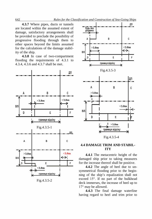
Rules for the Classification and Construction of Sea-Going Ships 642
4.3.7 Where pipes, ducts or tunnels
are located within the assumed extent of
damage, satisfactory arrangements shall
be provided to preclude the possibility of
progressive flooding through them to
other spaces beyond the limits assumed
for the calculations of the damage stabil-
ity of the ship.
4.3.8 In case of two-compartment
flooding the requirements of 4.3.1 to
4.3.4, 4.3.6 and 4.3.7 shall be met.
Fig.4.3.5-1
Fig.4.3.5-2
Fig.4.3.5-3
Fig.4.3.5-4
4.4 DAMAGE TRIM AND STABIL-
ITY
4.4.1 The metacentric height of the
damaged ship prior to taking measures
for the increase thereof shall be positive.
4.4.2 The angle of heel due to un-
symmetrical flooding prior to the begin-
ning of the ship’s equalization shall not
exceed 15°. If no part of the bulkhead
deck immerses, the increase of heel up to
17° may be allowed.
4.4.3 The final damage waterline
having regard to heel and trim prior to
<3.0m >3.0m
>3.0m
>3.0m
<3.0m
>3.0m
<3.0m >3.0m
<3.0m
<3.0m

Part V. Subdivision 643
the beginning of the ship’s equalization
shall not be above the lower edge of
openings indicated in 3.3.4, through
which progressive flooding may take
place.
4.4.4 When any part of the bulkhead
deck beyond the limits of the flooded
compartments immerses, or margin of
damage stability is doubtful, damage sta-
bility at large angles of heel shall be in-
vestigated. It shall be shown that the val-
ue of a maximum arm of the righting lev-
er curve of a damaged ship is not less
than 0.1 m within the rated extent (20°)
in association with a range of the curve
with positive arms of at least 20о, the area
of the positive portion of the curve being
not less than 0.0175 mrad.
5. REQUIREMENTS FOR SHIPS IN SERVICE
5.1 BULK CARRIERS, ORE CAR-
RIERS AND COMBINATION
CARRIERS
5.1.1 Bulk carriers with single side
shell the design of which complies with
the requirements of 3.3.1.6.1, Part ІІ
“Hull”, having the length L1 150 m and
above, carrying solid bulk cargoes with
a density of 1000 kg/m3 and above, con-
structed on 1 July 1999 or later that
date, shall comply with the require-
ments of 4.4 at flooding of any forward
cargo hold under all loading cases up to
the summer load line.
The bulk carrier which forward
cargo hold is confined by the outer plat-
ing or double side skin construction
with a width less than 760 mm with a
length L1 150 m and above, built before
1 July 1999 carrying solid bulk cargoes
with density of 1780 kg/m3 and above,
shall comply with the requirements of
4.4 while flooding the fore cargo hold in
all cases of loading up to the summer
load line not later than the date of sur-
vey assigned in relation to the ship’s
age:
.1 for ships which age at 1 July
1998 is 20 years and more, the date of
the first intermediate (the second or the
third annual survey) or the first special
survey, which shall be carried out after 1
July 1998 is accepted, whichever is earli-
er;
.2 for ships which age at 1 July 1998
is 15 years and more, but less than 20
years, the date of the first special survey
which shall be carried out after 1 July
1998, but not later than 1 July 2002 is
accepted;
.3 for ships which age at 1 July 1998
is less than 15 years, the date of the third
special survey or the date when the ship’s
age becomes equal to 15 years is accept-
ed, whichever is later.
5.1.2 The following values of per-
meabilities shall be taken for the damage
stability calculations:
0.90 for loaded holds;
0.95 for empty holds.
5.1.3 The ships which do not comply
with the requirements of 5.1.1 may be
acquitted from this requirement provided
the following conditions are met:
.1 the programme of the fore hold
annual survey is replaced by the pro-
gramme approved at the full scale inter-
mediate survey as per Section 5 “Addi-
tional Surveys of Ships in Relation to
their Purpose, Cargo Transported and

Rules for the Classification and Construction of Sea-Going Ships 644
Hull Material” of the Rules for the
Classification Surveys of Ships in Ser-
vice”;
.2 the visual and audible alarm
shall be fitted in the wheelhouse for
signalling in case of:
flooding over two metres above the
double bottom in the stern part of each
cargo hold;
filling of bilge well of each hold up
to the upper level.
Such signalling system shall meet
the requirements of Part XI “Electrical
Equipment”;
.3 the ship shall be supplied with
detailed information on the effect of the
phased flooding of cargo hold and de-
tailed instructions as per Section 8 of
the International Safety Management
Code (ISM Code).3
Information shall include the data
and documents specified in 1.4.6.1 and
the results of damage trim and stability
calculations at stage-by-stage compart-
ment flooding under all conditions of
loading to the summer load line on an
even keel. When the ship meets the re-
quirements of 4.4 at a lesser draught,
the document shall contain a diagram of
maximum heights of the centre of gravi-
ty of the ship (limiting moments or min-
imum metacentric heights) plotted with
due regard to the trim and ship load.
The strength of the bulkhead shall be
taken into consideration.
The information shall contain a
summary table of calculation results
with indication of critical factors and
the data given in 1.4.6.1.5.
5.1.4 The ships which are assigned
3 Refer to IMO Resolution А.741(18) as
amended.
with the reduced freeboard as per Section
4 are considered compliant with the re-
quirements of 5.1.1.
5.1.5 Information on compliance
with the requirements of 5.1.1 to 5.1.3
shall be included in the Booklet required
by 1.4.8.7, Part II “Hull”.
5.1.6 Ships built before 1 July 2004
shall meet the requirements of 3.4.11.3 to
3.4.11.5 not later than the date of the first
periodical survey of a ship conducted
after 1 July 2004.
5.1.6.1 If flooding detection sensors
cannot be placed in the aft end of the car-
go hold within a distance less than or
equal to В/6 from the centerline, they
shall be located at both the port and star-
board sides of the cargo hold.
5.1.6.2 The upper sensor only may
be fitted in cargo holds of the ships being
subject to the requirement of 5.1.3; the
ships not complying with the require-
ments of 5.1.3.2 on 1 January 2004 shall
be fitted with flooding detection sensors
in cargo holds as per 3.4.12.3.1 (consid-
ering 5.1.6.1).

Part V. Subdivision 645
APPENDIX 1
GUIDELINES FOR THE PREPARATION OF SUBDIVISION AND
DAMAGE STABILITY CALCULATIONS
1 General
1.1 Purpose of the Guidelines
1.1.1 These guidelines serve the
purpose of simplifying the process of
the damage stability analysis, as experi-
ence has shown that a systematic and
complete presentation of the particulars
results in considerable saving of time
during the approval process.
1.1.2 A damage stability analysis
serves the purpose to provide proof of
the damage stability standard required
for the respective type of a ship. At pre-
sent, two different calculation methods,
the deterministic concept and the prob-
abilistic concept are applied.
1.2 Scope of analysis and docu-
ments on board
1.2.1 The scope of subdivision and
damage stability analysis is determined
by the required damage stability stand-
ard and aims at providing the ship’s
master with clear intact stability re-
quirements.
In general, this is achieved by de-
termining KG-respective GM-limit
curves (minimum operational metacen-
tric height), containing the admissible
stability values for the draught range to
be covered.
1.2.2 Within the scope of analysis
thus defined, all the possible or required
damage conditions depending on the
damage stability criteria to get the re-
quired stability standard will be deter-
mined. Depending on the type and size
of a ship, this may involve a considera-
ble amount of analysis.
1.2.3 The necessity to provide the
crew with the relevant information regard-
ing the subdivision of the ship is ex-
pressed. Therefore, the Damage Control
Plan (refer to 1.4.6.2 hereof) shall be per-
manently exhibited for the guidance of the
duty officer of the crew. In addition, In-
formation on Damage Trim and Stability
shall be always available on board (refer to
1.4.6.1 hereof).
2 Documents for submission
2.1 General details to be included in
the documents on board
2.1.1 The documents shall include, as
a minimum, the following details: princi-
pal dimensions, ship type, designation of
intact conditions, designation of damage
conditions and KG-respective GM-limit
curve.
2.2 General documents
2.2.1 For the checking of the input
data, the following shall be submitted:
.1 main dimensions;
.2 lines plan, plotted or numerically;
.3 hydrostatic data and righting lever
curves, including cross curves of stability
(as well as drawing of buoyant hull in-
cluded into righting lever calculations);
.4 definition of ships spaces and com-
partments with moulded volumes, centres
of gravity and permeability;
.5 layout plan for all watertight struc-
tures and bulkheads with all internal and
external opening points including their
connected spaces, and reference to the
source materials used in measuring the
spaces, such as general arrangement plan
and subdivision plan.
The subdivision limits, longitudinal,
transverse and vertical, shall be included;

Rules for the Classification and Construction of Sea-Going Ships 646
.6 light service condition;
.7 load line draught;
.8 coordinates of opening points
with their level of tightness (e.g.,
weathertight or unprotected);
.9 watertight door location coordi-
nates with pressure calculation;
.10 side contour and wind profile;
.11 cross and down flooding devic-
es and the calculations thereof accord-
ing to IMO Resolution MSC.362(92)
with information about diameter,
valves, pipe lengths and coordinates of
inlet/outlet;
.12 pipes in damaged area when the
destruction of these pipes results in pro-
gressive flooding;
.13 damage extensions and defini-
tion of damage cases.
2.3 Special documents
To confirm damage stability calcu-
lation results the following data and
documents shall be submitted.
2.3.1 Documents
2.3.1.1 Initial data:
.1 subdivision length;
.2 initial draughts and the corre-
sponding GM-values;
.3 required subdivision index R;
and
.4 attained subdivision index А
with a summary table of all contribu-
tions for all damaged zones.
2.3.1.2 Results for each damage case,
which contributes to the index А:
.1 draught, trim, heel, GM in damaged
condition;
.2 extent of the damage with probabil-
istic values p, v and r;
.3 righting lever curve (including
GZmax and range) with factor of survivabil-
ity and buoyancy s;
.4 list of critical weathertight and un-
protected openings with their angle of
immersion; and
.5 details of the ship spaces and com-
partments with amount of in-flooded wa-
ter, lost buoyancy with their centres of
gravity.
2.3.1.3 In addition to the requirements
of 2.3.1.2, particulars of non-contributing
damages to index A (sі=0 and pі > 0.00)
shall be submitted for passenger ships and
ro-ro ships fitted with long lower holds
including full details of the calculated
subdivision factors.
2.3.2 Special consideration
2.3.2.1 For intermediate conditions,
as stages before cross-flooding or before
progressive flooding, additional damage
trim and stability calculations shall be
submitted in the scope covering the
aforementioned items.

Part V. Subdivision 647
ANNEX 2
DETERMINATION OF THE MOULDED PENETRATION DEPTH
Fig. 2.1

Rules for the Classification and Construction of Sea-Going Ships 648
N o t e s t o Fig.2.1: 1. Each drawing given in Fig. 2.1 represents an area of a single damage at the
waterline ds, the longitudinal bulkhead is a location of the outer bulkhead being lower than ds +12.5 m.
2. The penetration depth b is measured at level-keel draught under the deepest subdivision load line
ds as a transverse distance from the side at right angle to the centreline at the level of longitudinal limiting
construction (watertight bulkhead).
3. If the watertight bulkhead does not provide an area parallel to the plating, the size b shall be de-
termined via the assumed line dividing the area up to the shell under the ratio b1 /b2, as ½ ≤ b1 /b2 ≤ 2.