1 Networks A collection of transmitters, receivers or transceivers that communicate with each other...
62
1 Networks A collection of transmitters, receivers or transceivers that communicate with each other is known as a network. Digital networks may consist of one or more routers that route information to the correct user. An analogue network may consist of one or more switches that establish a connection between two or more users. For both types of network, repeaters may be necessary to amplify or recreate the signal when it is being transmitted over long distances. This is to combat attenuation that can render the signal indistinguishable from noise. Channels A channel is a division in a transmission medium so that it can be used to send multiple streams of information. For example, a radio station may broadcast at 96 MHz while another radio station may broadcast at 94.5 MHz. In this case, the medium has been divided by frequency and each channel has received a separate frequency to broadcast on. Alternatively, one could allocate each channel a recurring segment of time over which to broadcast — this is known as time-division multiplexing and is sometimes used in digital communication. Modulation The shaping of a signal to convey information is known as modulation. Modulation can be used to represent a digital message as an analogue waveform. This is known as keying and several keying techniques exist (these include phase- shift keying, frequency-shift keying and amplitude-shift keying). Bluetooth, for example, uses phase-shift keying to exchange information between devices. Modulation can also be used to transmit the information of analogue signals at higher frequencies. This is helpful because low-frequency analogue signals cannot be effectively transmitted over free space. Hence the information from a low-frequency analogue signal must be superimposed on a higher-frequency signal (known as a carrier wave) before transmission. There are several different modulation schemes available to achieve this 5. Network Configuration
Transcript of 1 Networks A collection of transmitters, receivers or transceivers that communicate with each other...

1
NetworksA collection of transmitters, receivers or transceivers that communicate with each other is known as a network. Digital networks may consist of one or more routers that route information to the correct user. An analogue network may consist of one or more switches that establish a connection between two or more users. For both types of network, repeaters may be necessary to amplify or recreate the signal when it is being transmitted over long distances. This is to combat attenuation that can render the signal indistinguishable from noise.
ChannelsA channel is a division in a transmission medium so that it can be used to send multiple streams of information. For example, a radio station may broadcast at 96 MHz while another radio station may broadcast at 94.5 MHz. In this case, the medium has been divided by frequency and each channel has received a separate frequency to broadcast on. Alternatively, one could allocate each channel a recurring segment of time over which to broadcast — this is known as time-division multiplexing and is sometimes used in digital communication.
ModulationThe shaping of a signal to convey information is known as modulation. Modulation can be used to represent a digital message as an analogue waveform. This is known as keying and several keying techniques exist (these include phase-shift keying, frequency-shift keying and amplitude-shift keying). Bluetooth, for example, uses phase-shift keying to exchange information between devices.Modulation can also be used to transmit the information of analogue signals at higher frequencies. This is helpful because low-frequency analogue signals cannot be effectively transmitted over free space. Hence the information from a low-frequency analogue signal must be superimposed on a higher-frequency signal (known as a carrier wave) before transmission. There are several different modulation schemes available to achieve this (two of the most basic being amplitude modulation and frequency modulation). An example of this process is a DJ's voice being superimposed on a 96 MHz carrier wave using frequency modulation (the voice would then be received on a radio as the channel “96 FM”).
5. Network Configuration

2
Network topology is the study of the arrangement or mapping of the elements (links, nodes, etc.) of a network, especially the physical (real) and logical (virtual) interconnections between nodes.A local area network (LAN) is one example of a network that exhibits both a physical and a logical topology. Any given node in the LAN will have one or more links to one or more other nodes in the network and the mapping of these links and nodes onto a graph results in a geometrical shape that determines the physical topology of the network. Likewise, the mapping of the flow of data between the nodes in the network determines the logical topology of the network. It is important to note that the physical and logical topologies might be identical in any particular network but they also may be different.Any particular network topology is determined only by the graphical mapping of the configuration of physical and/or logical connections between nodes - Network Topology is, therefore, technically a part of graph theory. Distances between nodes, physical interconnections, transmission rates, and/or signal types may differ in two networks and yet their topologies may be identical.

3
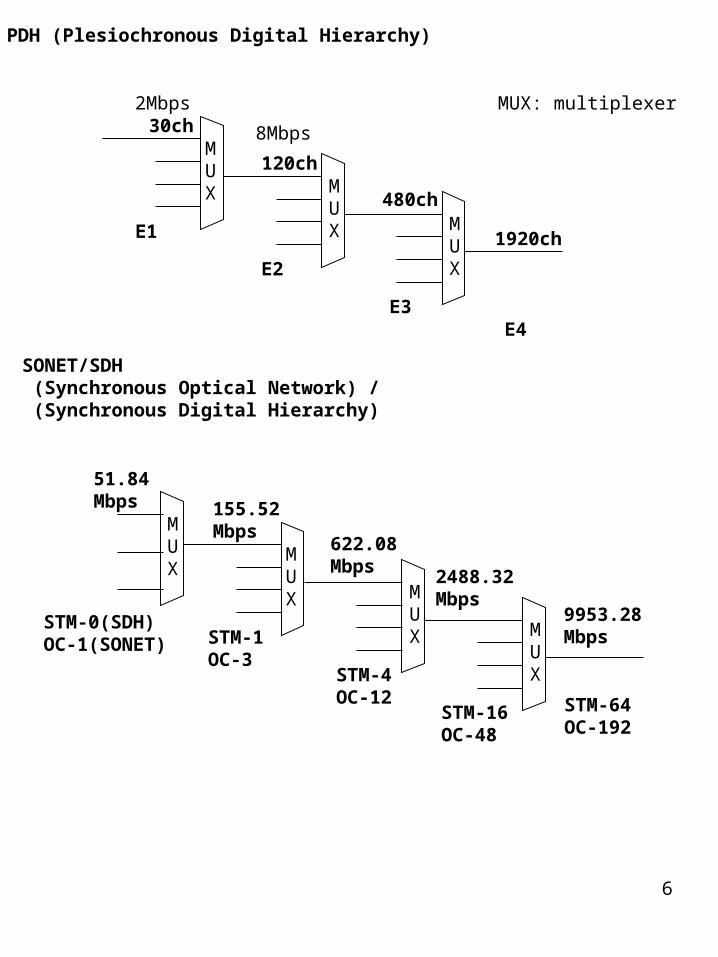
Public switched telephone networkFrom Wikipedia, the free encyclopedia. The public switched telephone network (PSTN) is the concatenation of the world's public circuit-switched telephone networks, in much the same way that the Internet is the concatenation of the world's public IP-based packet-switched networks. Originally a network of fixed-line analog telephone systems, the PSTN is now almost entirely digital, and now includes mobile as well as fixed telephones. The PSTN is largely governed by technical standards created by the ITU-T, and uses E.163/E.164 addresses (known more commonly as telephone numbers) for addressing. The basic digital circuit in the PSTN is a 64-kilobit-per-second channel, originally designed by Bell Labs, called a "DS0" or Digital Signal 0. To carry a typical phone call from a calling party to a called party, the audio sound is digitized at an 8 kHz sample rate using 8-bit pulse code modulation. The DS0's are the basic granularity at which switching takes place in a telephone exchange. DS0's are also known as timeslots because they are multiplexed together in a time-division fashion. Multiple DS0's are multiplexed together on higher capacity circuits, such that 24 DS0's make a DS1 signal, which when carried on copper is the well-known, T-carrier system, T1 (the European equivalent is an E1, containing 32 64 kbit/s channels). In modern networks, this multiplexing is moved as close to the end user as possible, usually into cabinets at the roadside in residential areas, or into large business premises. The timeslots are conveyed from the initial multiplexer to the exchange over a set of equipment collectively known as the access network. The access network and inter-exchange transport of the PSTN use synchronous optical transmission (SONET and SDH) technology, although some parts still use the older PDH technology. Within the access network, there are a number of reference points defined. Most of these are of interest mainly to ISDN but one - the V reference point - is of more general interest. This is the reference point between a primary multiplexer and an exchange. The protocols at this reference point were standardised in ETSI areas as the V5 interface.
4
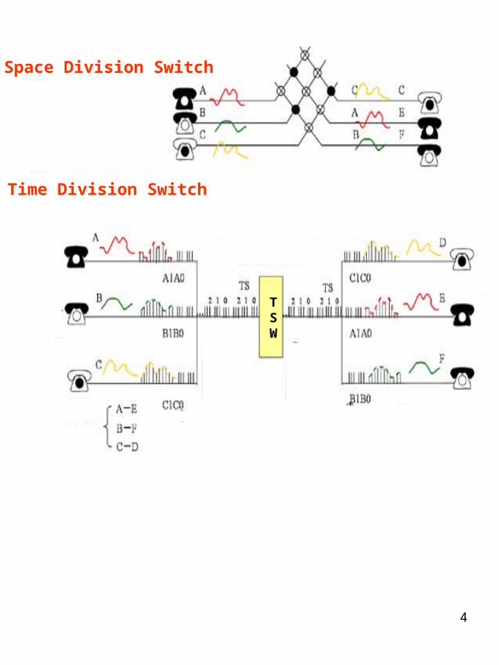
Space Division Switch
Time Division Switch
TSW

5
Only the very oldest and most backward parts of the telephone network still use analog technology for anything other than the last mile loop to the end user, and in recent years digital services have been increasing rolled out to end users using services such as DSL and ISDN. In the 1970s the telecommunications industry conceived that digital services would follow much the same pattern as voice services, and conceived a grandiose vision of end-to-end circuit switched services, known as the Broadband Integrated Services Digital Network (B-ISDN). The B-ISDN vision has been overtaken by the disruptive technology of the Internet. Many observers believe that the long term future of the PSTN is to be just one application of the Internet - however, the Internet has some way to go before this transition can be made: see the article on Voice over IP for more on this subject. The PSTN was the earliest example of traffic engineering to deliver Quality of Service guarantees. (See the work of A.K. Erlang for some history on this). Note: there are also a number of large private telephone networks which are not linked to the PSTN, usually for military purposes. There are also private networks run by large companies which are linked to the PSTN only through limited gateways, like a large PABX system.
6
PDH (Plesiochronous Digital Hierarchy)
30ch
120ch
480ch
1920ch
2Mbps
8Mbps
E1
E2
E3E4
MUX: multiplexer
MUX M
UX M
UX
SONET/SDH (Synchronous Optical Network) / (Synchronous Digital Hierarchy)
STM-1OC-3
STM-4OC-12
STM-16OC-48
STM-64OC-192
MUX M
UX M
UX
STM-0(SDH)OC-1(SONET)
MUX
155.52Mbps
622.08 Mbps
2488.32 Mbps
9953.28 Mbps
51.84Mbps

7
Voice Signal Control Signal
Voice Network
Control Network
PSTN Telephone SwitchTelephone Switch
Telephone Switch
8
V5 is a set of protocols defined by ETSI by which a multiplexer in the access network of the PSTN can communicate with a telephone exchange. The protocols are designed to handle both POTS and ISDN traffic. They are based on the principle of common channel signalling where message-based signalling for all subscribers uses the same signalling channel(s) rather than separate channels existing for different subscribers.
V5 comes in two forms:
V5.1 which there is a 1 to 1 correspondence between subscriber lines and bearer channels in the aggregate link to the exchange. A V5.1 interface relates to a single aggregate E1 (2 Mbit/s) link between a multiplexer and an exchange. V5.2 which provides for concentration where there are not enough bearer channels in the aggregate link(s) to accommodate all subscribers at the same time. A single V5.2 interface can control up to 16 E1 links at once and can include protection of the signalling channels.
V5 Interface

9
V5 is a standardized protocol suite for the connection of Access Networks (AN) to the Local Exchange (LE). The Access Network itself typically has PSTN and ISDN interfaces (user ports) to the customer. The V5 interfaces are based on G.703/G.704 interfaces at 2048 kbit/s (E1). V5.1 is a single 2048 kbit/s interface, whereas V5.2 may consist of one or up to sixteen 2048 kbit/s links, provisionable by the operator. Note that Access Network (AN) is often also referenced as Line Termination (LT) and Local Exchange (LE) as Exchange Termination (ET).
Time slot 0 (TS0) of the 32 time slots is always used for frame alignment, error reporting and error performance monitoring using cyclic redundancy check procedures. In case of V5.2 links, TS0 is additionally used to verify the correct physical connection of a 2048 kbit/s link. Up to three time slots on each 2048 kbit/s link may be assigned as so-called communication channels (C-channels). C-channels carry PSTN signalling, ISDN D-channel information, control information and, in case of V5.2 the bearer channel connection protocol (BCC) and the protection protocol. All 64 kbit/s time slots not provisioned as C-channels are available as PSTN or ISDN bearer channels or may carry analogue or digital leased lines.
Q interface
Access Network Local Exchange

10
Telecommunication Systems = Transportation Systems
< Speed, Cheap, Safety >

11
Packet
Information
InformationAddress Check
Packet

12
Thailand
Europe USA
Database
Thailand
Europe USA
Database
Database
Database
DatabaseNetwork
Satellite Office Type Idea for Reduction of Traffic
(Satellite Office)
(Satellite Office)

13
Different Packet Price
Expensive Price Cheap Price
Big Packet Small Packet
14
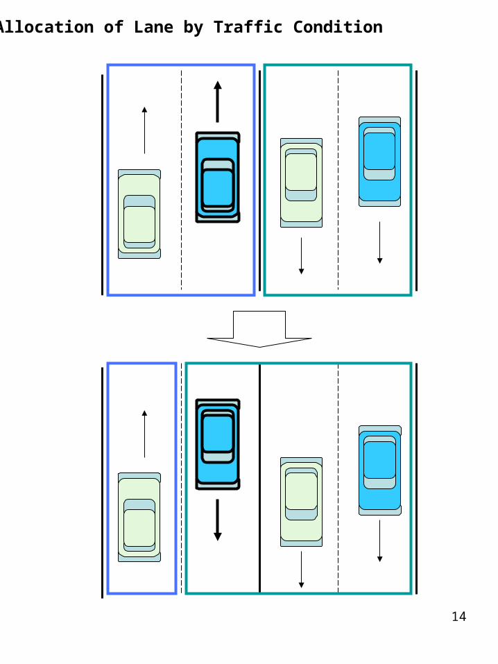
Allocation of Lane by Traffic Condition

15
Small Packet Overtake Big Packet

16
In telecommunications, a circuit switching network is one that establishes a fixed bandwidth circuit (or channel) between nodes and terminals before the users may communicate, as if the nodes were physically connected with an electrical circuit. The bit delay is constant during the connection, as opposed to packet switching, where packet queues may cause varying delay.Each circuit cannot be used by other callers until the circuit is released and a new connection is set up. Even if no actual communication is taking place in a dedicated circuit then, that channel still remains unavailable to other users. Channels that are available for new calls to be set up are said to be idle.
For call setup and control (and other administrative purposes), it is possible to use a separate dedicated signalling channel from the end node to the network. ISDN is one such service that uses a separate signalling channel while Plain Old Telephone Service (POTS) does not.The method of establishing the connection and monitoring its progress and termination through the network may also utilize a separate control channel as in the case of links between telephone exchanges which use CCS7 packet-switched signalling protocol to communicate the call setup and control information and use TDM to transport the actual circuit data.Early telephone exchanges are a suitable example of circuit switching. The subscriber would ask the operator to connect to another subscriber, whether on the same exchange or via an inter-exchange link and another operator. In any case, the end result was a physical electrical connection between the two subscribers' telephones for the duration of the call. The copper wire used for the connection could not be used to carry other calls at the same time, even if the subscribers were in fact not talking and the line was silent.
circuit switching:

17
Time
Time Division Modulation
T1 or E1
DSU: Digital Service Unit (in case of Analog, DCE: Data Circuit terminating Equipment i.e. Modem ) DTE : Data Terminal Equipment

18
TelephoneSwitch
TelephoneSwitch
A B
C D
A C
B D
B
A A
C
D
C
D
B
E1
E1
Ch1 Ch30
Ch1 Ch30
2 lines4 Lines
Circuit Switching
Its used Ch1 during call connection A and B.
Its used Ch30 during call connection C and D.

19
Lane 1for Mr. A
Lane 2for Mr. B
Lane3for Mrs. C
Lane 4for Miss D
20
Integrated services digital network (ISDN):There are two points of view into the ISDN world. The most common viewpoint is that of the end user who wants to get a connection into the telephone/data network at home, something a little better than a modem connection. Most of the links that would be on the Internet are related to this point of view and talk about the merits of various ISDN modems, carrier's offerings and tarriffing (features, pricing). Much of the following discussion is from this point of view and correctly points out that from this viewpoint, ISDN is mostly superseded by DSL as a viable connection to the Internet. There is however a second viewpoint, that of the telephone industry, where ISDN is not a dead issue. The telephone network in some ways is a collection of wires strung between switching systems. The common electrical specification for the signals on these wires is T1 or E1. On a normal T1, the signalling is done with A&B bits to indicate on or off hook conditions and MF and DTMF tones to encode the destination number. ISDN is much better than this as messages can be sent much more quickly than by trying to encode numbers as long (100 ms per digit) tone sequences. This translated to much faster call setup times which is greatly desired by carriers who have to pay for line time and also by callers who hate to wait while their call hops from switch to switch. It is also used as a smart network technology.
There are two kinds of access to ISDN: Basic Rate Interface (BRI) - consisting of two 64 kbit/s digital data channels and a 16 kbit/s digital signalling channel, designated as 2B+D, and, Primary Rate Interface (PRI) - containing a greater number of channels, based on the country:
North America and Japan: 23B+1D, aggregate bit rate of 1.544 Mbit/s (T1) Europe, Australia: 30B+D, aggregate bit rate of 2.048 Mbit/s (E1)
Calls are made over the data (B) channels, with the signalling (D) channels used for call setup and management. Once a call is set up, there is a simple 64 kbit/s synchronous bidirectional data channel between the users, lasting until the call is terminated. There can be as many calls as there are data channels, to the same or different end-points. Data channels may also be multiplexed into what may be considered single, higher-bandwidth channels.

21
DSU: Digital Service UnitTA: Terminal Adapter
serial port
TEL
2B+D
Line1B or 2B
1B1B1B
B (64Kbps)D (16Kbps)
(Ping-pong)
SW

22
1B
2B

23
P S T N
Packet Switch
Circuit Switch
TEL
FAX
TV
DATA
DATA

24
Asynchronous Transfer Mode (ATM):
ATM is a cell relay, packet switching network and data link layer protocol which encodes data traffic into small (53 bytes; 48 bytes of data and 5 bytes of header information) fixed-sized cells. ATM provides data link layer services that run over Layer 1 links. This differs from other technologies based on packet-switched networks (such as the Internet Protocol or Ethernet), in which variable sized packets (known as frames when referencing layer 2) are used. ATM is a connection-oriented technology, in which a logical connection is established between the two endpoints before the actual data exchange begins.Asynchronous, in the context of ATM, means that sources are not limited to sending data during a set time slot, which is the case with circuit switching, used in the old standby T1. ATM transmits data not in bits or frames, but in packets. Actually, in ATM parlance, the packets are called cells. Cells are fixed in length and are composed of two parts: the header and the data.
5 bytes 48 bytes
53 bytes
Header Data
Information Information
addition ofcell header(5 bytes)
divided by cell
asynchronous cell insert
empty cell
synchronous Transmission

25
Telephone Network
Data Network
ATMSwitching
Packet Packet
32 Bytes
64 Bytes
48 Bytes

26
GFC: Generic Flow Control VPI: Virtual Path Identifier VIC: Virtual Channel Identifier PT: Payload Type ( Congestion Control )CLP: Cell Loss Priority HEC: Header Error Control
GFC VPI VIC PT CLP
HEC DATA
4 8 16 3 1 8 bits
Header

27
ATM Cell
ATM CellATM Cell
Random
Synchronous
53 bytes
FDDI 60 Mbps
ATM 156 Mbps
1 G bytes File Load
2 min
1 min
FDDI: Fiber-Distributed Data Interface

28
for B
for B Send it with a label
It is not delay because of a small box.

29
ATM
Switch Queue
IN 1
IN 2
IN 3
OUT 1
OUT 2
OUT 3
OUT 1OUT2
OUT3OUT 1
OUT 2OUT 3
Header Translator

30
ATM Switching System
A BC
DEF A B
C DE
F

31
TV Telephone
Broadcasting
VPI: Virtual Path Identifier (8 bits)VCI: Virtual Channel Identifier (16 bits)
ATM Cable
Multiplex Communication

32
to A area
to Bto C
to A
to B
to DChangeArea
STM ATM
Reduce
Virtual Channel
Virtual Channel
Virtual Channel
Channel
Channel
Channel

33
Ethernet
IEEE 802.3
ATM
Band wide 10Mbps100Mbps
155.52Mbps STM-1/OC-3
Data frame 64 ~ 1518 bytes 53 bytes
Address 6 bytes ( 48 bits) 20 bytes (160 bits)

34
Digital signal processing (DSP) is the study of signals in a digital representation and the processing methods of these signals. DSP and analog signal processing are subsets of signal processing. It has three major subfields: audio signal processing, digital image processing and speech processing. In DSP, engineers most commonly study digital signals in one of the following domains: time domain (one-dimensional signals), spatial domain (multidimensional signals), frequency domain, autocorrelation domain, and wavelet domains. They choose the domain in which to process a signal by making an educated guess (or trying out different possibilities) as to which domain best represents the essential characteristics of the signal. A sequence of samples from a measuring device produces a time or spatial domain representation, whereas a discrete Fourier transform produces the frequency domain information. The autocorrelation is, loosely speaking, defined as the expected value of correlation of the signal with itself on some distance in time or spatial distance.
Typical applications of digital signal processing are, for example, speech compression and transmission in (digital) mobile phones, equalisation of sound in Hifi-equipment, weather forecasting and economic forecasting, analysis and control of industrial processes, computer-generated animations in movies and image manipulation.
35
The most well-known use of packet switching is the Internet and local area networks (LAN). The Internet uses the Internet protocol suite over a variety of data link layer protocols. For example, Ethernet and Frame relay are very common. Newer mobile phone technologies (e.g., GPRS, I-mode) also use packet switching.X.25 is a notable use of packet switching in that, despite being based on packet switching methods, it provided virtual circuits to the user. These virtual circuits carry variable-length packets In 1978, X.25 was used to provide the first international and commercial packet switching network, the International Packet Switched Service (IPSS). Asynchronous Transfer Mode (ATM) also is a virtual circuit technology, which uses fixed-length cell relay connection oriented packet switching.
Packet switching:

36
Channel Occupation
Packet
Non-Occupation Channel
Circuit Switch
Packet Switch

37
Circuit SW Packet SW
LabelPacket
Memory
ATM SW
fix length Cell
CellLabel
Delay Not effective use

38
Circuit SW Packet SW ATM SW
Not Effective Delay Effective & Early

39
Switching is a technology that alleviates congestion in Ethernet, Token Ring, and Fiber Distributed Data Interface (FDDI) LANs by reducing traffic and increasing bandwidth. Such switches, known as LAN switches, are designed to work with existing cable infrastructures so that they can be installed with minimal disruption of existing networks. Often, they replace shared hubs.
The term switching was originally used to describe packet-switch technologies, such as Link Access Procedure, Balanced (LAPB), Frame Relay, Switched Multimegabit Data Service (SMDS), and X.25. Today, switching refers to a technology that is similar to a bridge in many ways. The term bridging refers to a technology in which a device (known as a bridge) connects two or more LAN segments. A bridge transmits datagrams from one segment to their destinations on other segments. When a bridge is powered and begins to operate, it examines the Media Access Control (MAC) address of the datagrams that flow through it to build a table of known destinations. If the bridge knows that the destination of a datagram is on the same segment as the source of the datagram, it drops the datagram because there is no need to transmit it. If the bridge knows that the destination is on another segment, it transmits the datagram on that segment only. If the bridge does not know the destination segment, the bridge transmits the datagram on all segments except the source segment (a technique known as flooding). The primary benefit of bridging is that it limits traffic to certain network segments. Like bridges, switches connect LAN segments, use a table of MAC addresses to determine the segment on which a datagram needs to be transmitted, and reduce traffic. Switches operate at much higher speeds than bridges, and can support new functionality, such as virtual LANs.
LAN Switching:

40
W-LAN Switch
AP
W-LAN ControllerData
Control
PCPC
PCPC
AP
Server
Server

41
W-LAN Multi Channel Roaming
Channel 1Channel 5AP1
AP2
Channel 1
Channel 2
Channel 3
Channel 4
Channel 5
Channel 6 Channel 11
Channel 7
Channel 8
Channel 9
Channel 10
Channel 12
Channel 13
Channel 14
2.4GHz Channel Allocation

42
Wi-Fi ( Wireless Fidelity )
OFDM: Orthogonal Frequency DivisionDSSS: Direct Sequence Spread SpectrumMIMO: Multiple Input Multiple Output

43
Ethernet is a packet-based computer networking technology for local area networks (LANs). It defines wiring and signaling for the physical layer, and packet formats and protocolss for the media access control (MAC)/data link layer of the OSI model. Ethernet is mostly standardized as IEEE's 802.3. It has become the most widespread LAN technology in use during the 1990s to the present (2003), and has largely replaced all other LAN standards such as token ring, FDDI, and ARCNET.

44
Ethernet frame format
IEEE 802.3
Data
6 6 2 46 ~ 1500 4
( Bytes )
FCS
SOUADR
DESADR
Type
DES: DestinationSOU: SourceFCS: Frame Check Sequence
8
Sync

45
CSMA/CD: Carrier Sense Multiple Access/Collision Detection
Why is this technology not used on 10GbEthernet anymore ?
Why is the procedure speed of CSMA/CD down to 50%, if it have high traffic ?
data send from A
collision with B
collision detection by B
collision detection by B
<Collision Domain>

46
Wireless MAN - metropolitan area network Wireless LAN - local area networks Wireless PAN - personal area networks GSM - Global standard for digital mobile communication, common in most countries except South Korea and Japan PCS - Personal communication system - not a single standard, this covers both CDMA and GSM networks operating at 1900 MHz in North America Mobitex - pager-based network in the USA and Canada, built by Ericsson, now used by PDAs such as the Palm VII and Research in Motion BlackBerry GPRS - General Packet Radio Service, upgraded packet-based service within the GSM framework, gives higher data rates and always-on service UMTS - Universal Mobile Telephone Service (3rd generation cell phone network), based on the W-CDMA radio access network AX.25 - amateur packet radio NMT - Nordic Mobile Telephony, analog system originally developed by PTTs in the Nordic countries AMPS - Advanced Mobile Phone System introduced in the Americas in about 1984. D-AMPS - Digital AMPS, also known as TDMA Wi-Fi - Wireless Fidelity, widely used for Wireless LAN, and based on IEEE 802.11 standards. WiMAX - A solution for BWA (Broadband Wireless Access) and conforms to IEEE 802.16 standard. Canopy - A wide-area broadband wireless solution from Motorola.
Wireless network :

47
Cellular Phone
W-LAN
Satellite
Taxi
Personal
Radar
LittleWide
Weak
Capacity
CoverArea Go
ahead
Big
Narrow
Strong
Broadcast
Broadcast
TV
IrDA
Universe
Ship, Air
Ship, Air
Amateur
Amateur
1~ 30 GHz
λ x ƒ = vλ: wavelength
ƒ: Frequency
v: speed of electromagnetic wave
300GHz = 3 x 10 8
1 x 10 -3= 3 x 10 11

48
The global system for mobile communications (GSM) GSM exists in four main versions, based on the band used: GSM-900, GSM-1800, GSM-850 and GSM-1900. GSM-900 (900 MHz) and GSM-1800 (1.8 GHz) are used in most of the world, excluding the United States and Canada. The United States and Canada use GSM-850 and GSM-1900 (1.9 GHz) instead, since in the U.S. the 900 and 1800 bands were already allocated. GSM-900 uses 890-915MHz to send information and 935-960MHz to receive information. GSM-1800 uses 1710-1785MHz to send information and 1805-1880 to receive information. In some countries the GSM-900 band has been extended to cover a larger frequency range. In Europe and other areas outside North America the GSM system initially used a frequency of 900 MHz, shortly afterwards the PCN network used the 1800 MHz frequency, nowadays the PCN networks are considered part of the GSM system and many phones are dual-band operating on 900/1800 MHz. In GSM, a call is dedicated either as voice or data. A voice call uses a GSM specific codec to transmit the audio over a 9600 bit/s digital link to the base station.

49
Service area of GSM
50
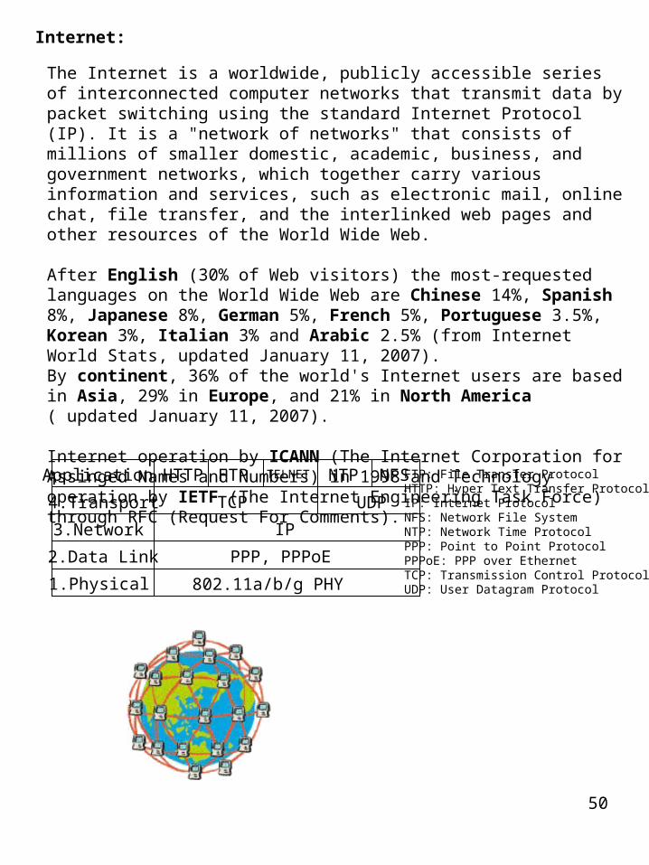
The Internet is a worldwide, publicly accessible series of interconnected computer networks that transmit data by packet switching using the standard Internet Protocol (IP). It is a "network of networks" that consists of millions of smaller domestic, academic, business, and government networks, which together carry various information and services, such as electronic mail, online chat, file transfer, and the interlinked web pages and other resources of the World Wide Web.
After English (30% of Web visitors) the most-requested languages on the World Wide Web are Chinese 14%, Spanish 8%, Japanese 8%, German 5%, French 5%, Portuguese 3.5%, Korean 3%, Italian 3% and Arabic 2.5% (from Internet World Stats, updated January 11, 2007).By continent, 36% of the world's Internet users are based in Asia, 29% in Europe, and 21% in North America ( updated January 11, 2007).
Internet operation by ICANN (The Internet Corporation for Assinged Names and Numbers) in 1998 and Technology operation by IETF (The Internet Engineering Task Force) through RFC (Request For Comments).
Internet:
TCP
IP
PPP, PPPoE
HTTP FTP TELNET NTP NFS
UDP
1.Physical
Application
2.Data Link
3.Network
4.Transport
802.11a/b/g PHY
FTP: File Transfer ProtocolHTTP: Hyper Text Transfer ProtocolIP: Internet ProtocolNFS: Network File SystemNTP: Network Time ProtocolPPP: Point to Point ProtocolPPPoE: PPP over EthernetTCP: Transmission Control ProtocolUDP: User Datagram Protocol

51
Provider
Internet eXchange

52
Europe ISP
America ISPAfrica ISP
Other Countries ISP
Asia Area ISP

53
Provider D
Provider C
Provider B
Provider A
Modem
Modem
Router
RouterHub
Router
Hub
Client
Client
www ServerDNS ServerMail Server
Proxy Server (Firewall)

54
WWW Server (Home Page) SMTP Server (E-mail) POP Server (Mail Box access)FTP Server (File)Proxy ServerDNS Server Domain/IP address
WWW Server
Proxy
Provider A
Provider A
Server

55
5. Application
4. Transport
3. Internet
2. Network Link
1. Physical

56
PSTN and IP Integrated Network
Signaling &Management
New Interface Function

57
Internet
Server Server
Router Router
HQBranchOffice
TEL TEL
VoIP : Voice over Internet Protocol

58
VoIP Gateway
Gateway Gateway
IP Packet AnalogSignal
TEL TEL
Con.
Con.
Con.
Echo
STOP
COM
EXP
IP
Packet
IPNW
IPNW

59
RMI (Remote Method Invocation)
Call
Answer
Server Client
Remote Object Object
Java Application Program Java Applet Program
Same as CORBA(Common Object Request Broker Architecture )
If Client connect by Proxy,it maybe not success.Because Proxy use only port 80.
Hello .html Down Load
Hello World !Send Back
( Distributed Object Technology)

60
Routing by IPaddress
Routing by IPaddress
Routing by IPaddress
Packet
Packet
Path Setting
Put Label byIP address
Label
Routing byLabel
Routing byLabel
Routing:
MPLS: Multi Protocol Label Switching

61
Routing byMPLS
can not be used
Routing byIGP
Congestion
MPLS: Multi Protocol Label Switching
IGP: Interior Gateway Protocol, Example RIP or OSPFRIP: Routing Information ProtocolOSPF: Open Shortest Path First

62
Microsoft® Exchange Server 2003 and Microsoft Exchange 2000 Server support using a server architecture that distributes server tasks among front-end and back-end servers. In this architecture, a front-end server accepts requests from clients and proxies them to the appropriate back-end server for processing. This guide discusses how Exchange Server 2003 and Exchange 2000 Server support the front-end and back-end server architecture. Also covered are several front-end and back-end scenarios and recommendations for configuration.
Exchange Server:
DatabaseAccessRequest
Front-end server
Back-endserver
Control server