1 Mortise - Intermountain Lock & Security Supply
10
Kaba Access Control 2941 Indiana Avenue Winston-Salem, NC 27105 USA Tel: (800) 849-8324 (336) 725-1331 Fax: (800) 346-9640 (336) 725-3269 www.kabaaccess.com www.e-plexlock.com PKG3140 0507 1" MORTISE INSTALLATION INSTRUCTIONS
Transcript of 1 Mortise - Intermountain Lock & Security Supply
Kaba Access Control2941 Indiana Avenue Winston-Salem, NC 27105 USATel: (800) 849-8324 (336) 725-1331Fax: (800) 346-9640 (336) 725-3269www.kabaaccess.com www.e-plexlock.com PKG3140 0507
1" MORTISEINSTALLATION INSTRUCTIONS
dirk.hickenlooper
IMLSS

2 3
TABLE OF CONTENTS
Tools Required . . . . . . . . . . . . . . . . . . . . . . . . . . . . . . . . . . . . . . . . . . . . . . . . . . . . . . . . . . . . . . . . .3
Exploded Install Parts . . . . . . . . . . . . . . . . . . . . . . . . . . . . . . . . . . . . . . . . . . . . . . . . . . . . . . . . . . .4
Handing Diagram . . . . . . . . . . . . . . . . . . . . . . . . . . . . . . . . . . . . . . . . . . . . . . . . . . . . . . . . . . . . . . .5
A. Mortise Handing . . . . . . . . . . . . . . . . . . . . . . . . . . . . . . . . . . . . . . . . . . . . . . . . . . . . . . . . . . . .5
B. Door Preparation . . . . . . . . . . . . . . . . . . . . . . . . . . . . . . . . . . . . . . . . . . . . . . . . . . . . . . . . . . .6
C. Installing the Strike . . . . . . . . . . . . . . . . . . . . . . . . . . . . . . . . . . . . . . . . . . . . . . . . . . . . . . . . .7
D. Installing Outside Unit Assembly . . . . . . . . . . . . . . . . . . . . . . . . . . . . . . . . . . . . . . . . . . . . .8
E. Installing Inside Unit Assembly . . . . . . . . . . . . . . . . . . . . . . . . . . . . . . . . . . . . . . . . . . . . . . .9
F. Installing the Inside Lever . . . . . . . . . . . . . . . . . . . . . . . . . . . . . . . . . . . . . . . . . . . . . . . . . . .9
G. Changing Key-In-Lever Cylinder . . . . . . . . . . . . . . . . . . . . . . . . . . . . . . . . . . . . . . . . . . . . . .10
H. Installing / Removing Outside Lever (Key-In-Lever) KIL . . . . . . . . . . . . . . . . . . . . . . . . . .11
I. Installing / Removing Outside Lever (Interchangeable/ . . . . . . . . . . . . . . . . . . . . . . . . . .11
removable core models)
J. Installing the Battery Pack and Cover . . . . . . . . . . . . . . . . . . . . . . . . . . . . . . . . . . . . . . . . .13
K. Testing the Operation of the Lock . . . . . . . . . . . . . . . . . . . . . . . . . . . . . . . . . . . . . . . . . . . .14
L. Reset Function . . . . . . . . . . . . . . . . . . . . . . . . . . . . . . . . . . . . . . . . . . . . . . . . . . . . . . . . . . . . .14
M. Installing Rubber Bumpers . . . . . . . . . . . . . . . . . . . . . . . . . . . . . . . . . . . . . . . . . . . . . . . . . .15
Introduction
The purpose of this manual is to instruct the installer on the properinstallation procedure for the E-Plex 5x63, 5x64, 5x68 and 5x69 1"American Steel Mortise (ASM) Mortise locks. These instructions pertainto models with and without deadbolts. For models without deadbolts,please disregard any references to a thumbturn in the instructions.
WarningThe Master Code of this lock has been factory preset: 1,2,3,4,5,6,7,8. To activatelock functions, the master combination must be changed at timeof installation.
Warnings and CautionsImportant: Carefully inspect windows, door frame, door, lights, etc.to ensure that the recommended procedures will not cause damage. KabaAccess Control’s warranty does not cover damages caused by installation.
Caution: Wear safety glasses when preparing door.
TOOLS REQUIRED• Safety glasses• 1⁄2" (13 mm) chisel• 1⁄8" (3 mm) drill bit• 1⁄4" (7 mm) drill bit• 1⁄2" (13 mm) drill bit• 21⁄8" (54 mm) hole saw• Drill• Awl or center punch• Hammer• Small flat screwdriver• Phillips screwdriver (#2)
• Fine steel file• Mortising machine• Router• Mortise faceplate router
template• Adjustable square• Tape measure• Pencil• Tape• Cleaning supplies
(drop cloth, vacuum)
OPERATIONAL NOTE:The E-Plex Mortise lock is almost identical to the E-Plex 5000 Cylindricallock with the following exceptions:
1. Operation of the Lever When the lock’s handing is properly set,only a downward rotation of lever will actuate latch.
2. Key Override Use The key override differs in that rotating the keydoes not actuate the latch. To use the key override the key must beinserted into the cylinder and rotated counter clockwise until itstops (approximately 90 degrees) then while holding the key in thisposition with one hand use the other hand to rotate the lever down-ward to retract the latch. Once the lever has rotated a few degreesthe key may be released.

54
For technical assistance please call1-800-849-TECH (8324) or 336-725-1331
INSTALLATION QUALIFICATIONSThese instructions are designed for use by maintenance professionals or lockinstallers who are familiar with common safety practices and competent toperform the steps described. Kaba Access Control is not responsible fordamage, injury or malfunction due to incorrect installation.
Handing DiagramTo determine handing, face the door from the exterior (access) side andselect the corresponding diagram below.
LH RH LHR RHR
Chart
Model Number Handing Deadbolt
E5x63 LH/RHR
E5x64 RH/LHR
E5x68 LH/RHR
E5x69 RH/LHR
Outside UnitAssembly
Outside LeverAssembly
MountingPlate
Mortise Lock
Mortise Faceplate
Strike
MortiseSpindle
ThumbturnSpindle
LowerMountingScrews Release
Tool
MountingPlate
Screws
AllenWrench
Battery CoverScrews
Battery Pack Cover
Battery Pack
LectroboltInside Unit Assembly
Inside Lever
SecurityScrew Tool
UpperMounting Screw
E-PLEX 1" Mortise Lock5x63, 5x64, 5x68 and 5x69
No
Yes
A. MORTISE HANDINGThe 1" Mortise is not field reversible. You must have theappropriate model for the door handing of the installation.
For LH (left hand) andRHR (right hand reverse)
For RH (right hand) andLHR (left hand reverse)
76
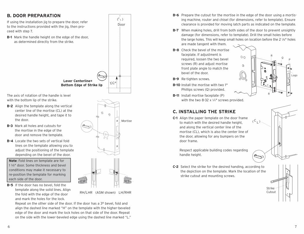
B-6 Prepare the cutout for the mortise in the edge of the door using a mortis-ing machine, router and chisel (for dimensions, refer to template). Ensureclearance is provided for moving latch parts as indicated on the template.
B-7 When making holes, drill from both sides of the door to prevent unsightlydamage (for dimensions, refer to template). Drill the small holes beforethe large holes. This will keep small holes on location before the 2 1⁄8" holesare made tangent with them.
B-8 Check the bevel of the mortisefaceplate. If adjustment isrequired, loosen the two bevelscrews (R) and adjust mortisefront plate angle to match thebevel of the door.
B-9 Re-tighten screws.
B-10 Install the mortise with two 1"Phillips screws (Q) provided.
B-11 Install mortise faceplate (P)with the two 8-32 x 1⁄4" screws provided.
C. INSTALLING THE STRIKEC-1 Align the paper template on the door frame
to match with the desired handle height,and along the vertical center line of themortise (CL), which is also the center line ofthe door, allowing for any bumpers on thedoor frame.
Respect applicable building codes regardinghandle height.
C-2 Select the strike for the desired handing, according tothe depiction on the template. Mark the location of thestrike cutout and mounting screws.
B. DOOR PREPARATIONIf using the installation jig to prepare the door, referto the instructions provided with the jig, then pro-ceed with step 7.
B-1 Mark the handle height on the edge of the door,as determined directly from the strike.
The axis of rotation of the handle is levelwith the bottom lip of the strike.
B-2 Align the template along the verticalcenter line of the mortise (CL) at thedesired handle height, and tape it tothe door.
B-3 Mark all holes and cutouts forthe mortise in the edge of thedoor and remove the template.
B-4 Locate the two sets of vertical foldlines on the template allowing you toadjust the positioning of the templatedepending on the bevel of the door.
Note: Fold lines on template are for1 3⁄8" door. Some thickness and bevelconditions may make it necessary tore-position the template for markingeach side of the door.
B-5 If the door has no bevel, fold thetemplate along the solid lines. Alignthe fold with the edge of the doorand mark the holes for the lock.Repeat on the other side of the door. If the door has a 3° bevel, fold andalign the dashed line marked “H” on the template with the higher-bevelededge of the door and mark the lock holes on that side of the door. Repeaton the side with the lower-beveled edge using the dashed line marked “L.”
RH/LHR (ASM shown) LH/RHR
11⁄4"
Door
(CL )
Lever Centerline=Bottom Edge of Strike lip
Mortise
P
Logo
QR
R
(CL)
StrikeCutout

98
E. INSTALLING INSIDE UNIT ASSEMBLYE-1 Place inside mounting plate flush against the door
as shown. For a door thicknesses of 1 3⁄8" insertdiagonally (as shown) two 1 1⁄2" Phillips flat headscrews (supplied in parts door kit).
Note: The screws must correspond to the twothrough holes in the mortise.
E-2 Insert the square spindle (G) into the inside housinghub.
E-3 Put the thumbturn (T), if applicable in a verticalposition and place the inside trim assembly onthe door so that the upper spindle (F) engagesthe thumbturn and mortise hubs, respectively.Ensure the red collar is seated into its mountinghole. Carefully push the inside housing flushagainst the door.
E-4 Supplied hardware should correspond to the chart below:
Door LectroBolt Top Mounting LowerThickness Size Screw Size Mounting Screws
1 3⁄8" 2 3⁄8" 2 1⁄2" 5⁄8"(35 mm) (60 mm) (64 mm) (16 mm)
E-5 Insert the LectroBolt™ through the red insidehousing hole marked with the lightening boltsymbol. For now, only partially tighten theLectroBolt™ to keep the red collars in position.
E-6 Then, insert and tighten the other three mountingscrews. (Refer to the chart for correct screwlengths.)
E-7 Finish tightening the LectroBolt™ to secure thelock on the door.
Warning: If using a power drill, please be careful not toover-tighten as this could cause damage to the mountingscrews and threads.
F. INSTALLING THE INSIDE LEVERInsert the inside lever (A) onto the inside unit assembly.Secure the inside lever with the hex screw (B) (supplied)using the allen wrench (C) (supplied).
C-3 Drill pilot holes for the strike mounting screws.Mortise the door frame for the strike dimensionsshown. 3 3⁄8" (L) X 1" (D) X 1" (W)
Note: Make certain not to mortiseover screw holes drilled earlier.
C-4 Position the strike against the door frame and alignit with the mounting screw holes. Then mark theoutline of the strike.
C-5 Remove any material from within the strike outline(a) so that the strike will be flush with the doorframe.
C-6 Install the strike using the screws provided.
D. INSTALLING OUTSIDEUNIT ASSEMBLY
Note: Ensure that the mounting hole for the redcollars is cleaned out so that the collars are notcrushed upon installation. If necessary, the holecan be opened up to 5⁄16".
D-1 For door thickness of 1 3⁄8", insert the squarespindle (G) into the outside housing hub.
D-2 If your lock comes with a thumbturn, insertthe end (with the ring groove) of the thumb-turn spindle (F) into the small spindle holein the outside housing.
D-3 Place the outside housing on the door so that the bottom spindle engagesthe hub on the mortise, and the top thumbturn spindle passes throughthe mortise top hub. The outside unit assembly (c) will rest flush againstthe door. Ensure the red collar is seated into the top left mounting hole.
3 3⁄8
F
G
T
C
RedCollar
G
F
a
Lectrobolt
5⁄8"(16mm)
a
cb

KA
BA
AC
CE
SS
CO
NT
RO
L29
41
IND
IAN
AA
VE
NU
EW
INS
TON
-SA
LE
M,N
C27
199
-377
0
NO
PO
STA
GE
NE
CE
SS
AR
YIF
MA
ILE
DIN
TH
EU
NIT
ED
STA
TE
S
BUSINESSREPLY
FIR
ST-C
LASS
MA
ILP
ER
MIT
NO
.15
63
PO
STA
GE
WIL
LB
EP
AID
BY
AD
DR
ES
SE
E
WIN
STO
N-S
ALE
M,N
C
Kaba Access Control warrants this product to be free from defects inmaterial and workmanship under normal use and service for a periodof three (3) years. Kaba Access Control will repair or replace, at ourdiscretion, 5000 Series Locks found by Kaba Access Control analysisto be defective during this period. Our only liability, whether in tort orin contract, under this warranty is to repair or replace products that arereturned to Kaba Access Control within the three (3) year warrantyperiod.
This warranty is in lieu of and not in addition to any other warranty orcondition, express or implied, including without limitation merchantabil-ity, fitness for purpose or absence of latent defects.
ATTENTION: This warranty does not cover problems arising out ofimproper installation, neglect or misuse. All warranties implied orwritten will be null and void if the lock is not installed properly and /orif any supplied component part is substituted with a foreign part. If thelock is used with a wall bumper, the warranty is null and void. If adoorstop is required, we recommend the use of a floor secured stop.
The environment and conditions of use determine the life of finisheson Kaba Access Control products. Finishes on Kaba Access Controlproducts are subject to change due to wear and environmentalcorrosion. Kaba Access Control cannot be held responsible for thedeterioration of finishes.
Authorization to Return GoodsReturned merchandise will not be accepted without prior approval.Approvals and Returned Goods Authorization Numbers (RGA Numbers)for the 5000 Series are available through our Customer Servicedepartment in Winston-Salem, NC (800) 849-8324. The serial numberof a lock is required to obtain this RGA Number. The issuance of anRGA does not imply that a credit or replacement will be issued.
The RGA number must be included on the address label when materialis returned to the factory. All component parts including latches andstrikes (even if not inoperative) must be included in the package withreturn. All merchandise must be returned prepaid and properly pack-aged to the address indicated.
* Simplex 5000 locks are warranted three (3) years from date ofpurchase. E-Plex 5x00 locks are warranted three (3) years fromdate of activation.
KABA E-PLEX® 5x00 SERIESLIMITED WARRANTY

Notes
Th
ank
you
for
pu
rchasin
go
ur
pro
du
ct.Ino
rder
top
rotect
you
rinvestm
ent
and
toen
able
us
tob
etterserve
youin
thefuture,please
filloutthis
registrationcard
and
return
itto
Kaba
Access
Co
ntro
l,or
register
on
line
atwww.ka
baaccess.co
m.
Thislock
willbe
used
inwhattype
offacility
?
�C
omm
ercialBuilding
�Industrial/
Manufacturing
�A
irport
�C
ollege/U
niversity�
Governm
ent/Military
�S
chool/Educational
�H
ospital/Healthcare
�O
ther(please
specify)
Whatarea
isbein
gsecu
redwith
thislock?
(e.g.FrontD
oor,Com
mon
Door,E
xerciseR
oom)
Thislock
is:
�N
ewInstallation
�R
eplacinga
conventionalkeyedlock
�R
eplacinga
Kaba
MechanicalP
ushbuttonLock
�R
eplacinga
Kaba
Electronic
Access
Control
�R
eplacinga
Keyless
Lockother
thanK
aba
How
didyou
learnabou
tKaba
Access
Control
Pushbutton
Locks?
�A
dvertisement
�P
reviousU
se�
Internet/
Web
�A
notherU
se
�Locksm
ith�
Maintenance
�Training
Class
�O
ther(please
specify)
Whatwas
yourreason
forbuyingthislock?
Whoinstalled
yourlock?
�Locksm
ith�
Maintenance
�O
ther
�Check
here
ifyou
wouldlike
more
information
onKaba
Access
Controllocks.
Nam
e
Position
Com
pany
Address
City
State
ZIP
(Po
stalCo
de)
Co
un
try
Phone
Em
ail
Nam
eof
Dealer
Purchased
From
Date
ofP
urchase
LockM
odelNum
ber
REGISTRATIONCARD

1110
H. INSTALLING / REMOVING OUTSIDE LEVER(Key-In-Lever models only)
H-1 Make certain the lever catch is up as shown (c).To successfully install the outside lever, thelever sleeve (f) tab must be positioned correct-ly with the respective notch on the lever. Thelock comes shipped with the lever sleevealready installed in the lock housing. Wheninstalling lever, ensure it is oriented to engagethe lever sleeve to accommodate desired lockhanding as shown.
H-2 Insert one of the supplied keys (a) into the out-side lever (b) and rotate key counterclockwise45 degrees.
H-3 Insert the outside lever (b) until it is flush tothe outside unit assembly (g). Secure the out-side lever by rotating the key (a) clockwise 45degrees to horizontal position. Remove key.
Note: To remove the outside lever from theoutside unit assembly, follow the step below.
H-4 Insert one of the supplied keys (a) into the outsidelever and rotate it counterclockwise 45 degrees.Insert release tool (d) into the small hole (e) underlever as shown. Gently push lever catch up until itclicks. Remove tool, then remove outside lever (b).
I. INSTALLING / REMOVING OUTSIDE LEVER(Interchangeable / Removable Core Models)
I-1 Make certain the lever catch is up as shown (c).To successfully install the outside lever, the leversleeve (f) tab must be positioned correctly withthe respective notch on the lever. The lock comesshipped with the lever sleeve already installed inthe lock housing. When installing lever, ensure itis oriented to engage the lever sleeve toaccommodate desired lock handing as shown.
Note: For all interchangeable/removable cylindersexcept ASSA/Medeco/Yale, proceed to section I-2.For ASSA/Medeco/Yale cylinders, skip to section I-5.
G. CHANGING KEY-IN-LEVER CYLINDEROn key-in-lever models of the E-Plex 5000 series, the outside lever comespreassembled with Kaba’s key-in-lever cylinder (Kaba 1599). To use a dif-ferent key-in-lever cylinder follow remaining steps in this section.
G-1 To remove KIL (key-in-lever) cylinder (a) from theoutside lever (b). Remove the cylinder insert (e)and the cylinder retainer (c) using a small flatbladed screwdriver or small needle nose pliers.
G-2 Determine the proper tailpiece (d) from thechart below for your KIL cylinder.You must use a Kaba tailpiece. The K 2 tailpiece is preassembled withthe Kaba 1599.
G-3 Assemble the required tailpiece (d) (from above)with your KIL cylinder. All tailpieces must beinstalled vertically (with key removed fromcylinder) for proper installation.
G-4 Insert the KIL cylinder (a) into the outside lever and secure it with thecylinder retainer (c) and the cylinder insert (e) until the KIL cylinder issnug and unable to move freely.
d
f
a
b
e
c
Assa 65611, Australian: Kaba experT 107K5 &Boyd KC286, Corbin-Russwin 2000-03, Kaba1599, Schlage 23-001, Schlage Primus 20-760,Kaba Peaks 1099
Medeco 20W200H1
Arrow C100, Sargent 10 LINE
Marks
Abloy 5277, Abloy 5477, Assa 65691,Kaba 1539, Kaba Gemini 4730
KIL CYLINDERTAILPIECE
K1
K3
K2
K4
K5
d
a
b
e
c
LH
KIL Lever Sleeve
RH
a
b
45º
ab
f
c
CorrectPosition
IncorrectPosition
45º
ed
g
g
IC Lever Sleeve
RHLH
f
c
CorrectPosition
IncorrectPosition
1312
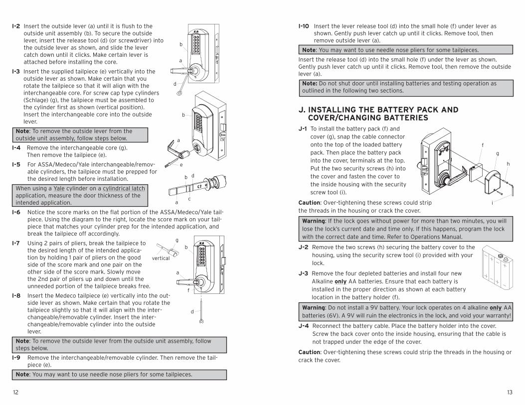
I-10 Insert the lever release tool (d) into the small hole (f) under lever asshown. Gently push lever catch up until it clicks. Remove tool, thenremove outside lever (a).
Note: You may want to use needle nose pliers for some tailpieces.
Insert the release tool (d) into the small hole (f) under the lever as shown.Gently push lever catch up until it clicks. Remove tool, then remove the outsidelever (a).
Note: Do not shut door until installing batteries and testing operation asoutlined in the following two sections.
J. INSTALLING THE BATTERY PACK ANDCOVER/CHANGING BATTERIES
J-1 To install the battery pack (f) andcover (g), snap the cable connectoronto the top of the loaded batterypack. Then place the battery packinto the cover, terminals at the top.Put the two security screws (h) intothe cover and fasten the cover tothe inside housing with the securityscrew tool (i).
Caution: Over-tightening these screws could stripthe threads in the housing or crack the cover.
Warning: If the lock goes without power for more than two minutes, you willlose the lock’s current date and time only. If this happens, program the lockwith the correct date and time. Refer to Operations Manual.
J-2 Remove the two screws (h) securing the battery cover to thehousing, using the security screw tool (i) provided with yourlock.
J-3 Remove the four depleted batteries and install four newAlkaline only AA batteries. Ensure that each battery isinstalled in the proper direction as shown at each batterylocation in the battery holder (f).
Warning: Do not install a 9V battery. Your lock operates on 4 alkaline only AAbatteries (6V). A 9V will ruin the electronics in the lock, and void your warranty!
J-4 Reconnect the battery cable. Place the battery holder into the cover.Screw the back cover onto the inside housing, ensuring that the cable isnot trapped under the edge of the cover.
Caution: Over-tightening these screws could strip the threads in the housing orcrack the cover.
I-2 Insert the outside lever (a) until it is flush to theoutside unit assembly (b). To secure the outsidelever, insert the release tool (d) (or screwdriver) intothe outside lever as shown, and slide the levercatch down until it clicks. Make certain lever isattached before installing the core.
I-3 Insert the supplied tailpiece (e) vertically into theoutside lever as shown. Make certain that yourotate the tailpiece so that it will align with theinterchangeable core. For screw cap type cylinders(Schlage) (g), the tailpiece must be assembled tothe cylinder first as shown (vertical position).Insert the interchangeable core into the outsidelever.
Note: To remove the outside lever from theoutside unit assembly, follow steps below.
I-4 Remove the interchangeable core (g).Then remove the tailpiece (e).
I-5 For ASSA/Medeco/Yale interchangeable/remov-able cylinders, the tailpiece must be prepped forthe desired length before installation.
When using a Yale cylinder on a cylindrical latchapplication, measure the door thickness of theintended application.
I-6 Notice the score marks on the flat portion of the ASSA/Medeco/Yale tail-piece. Using the diagram to the right, locate the score mark on your tail-piece that matches your cylinder prep for the intended application, andbreak the tailpiece off accordingly.
I-7 Using 2 pairs of pliers, break the tailpiece tothe desired length of the intended applica-tion by holding 1 pair of pliers on the goodside of the score mark and one pair on theother side of the score mark. Slowly movethe 2nd pair of pliers up and down until theunneeded portion of the tailpiece breaks free.
I-8 Insert the Medeco tailpiece (e) vertically into the out-side lever as shown. Make certain that you rotate thetailpiece slightly so that it will align with the inter-changeable/removable cylinder. Insert the inter-changeable/removable cylinder into the outsidelever.
Note: To remove the outside lever from the outside unit assembly, followsteps below.
I-9 Remove the interchangeable/removable cylinder. Then remove the tail-piece (e).
Note: You may want to use needle nose pliers for some tailpieces.
e
a
b
d
b
a
vertical
gb
d
f
a
f
h
i
g
ac
db
1514
For example, if your new code is 1,2,,7,2,4,6,8, the correct buttons to press inthe exact order are:
#1,2,3,4,5,6,7,8,#,0,0,0,#,1,3,5,7,2,4,6,8,#,#. To determine if you have successful-ly changed your master code, enter 1,3,5,7,2,4,6,8, and the lock should open.Now try the factory master code, 1,2,3,4,5,6,7,8 and the lock should not open.
Refer to the included Operations Manual for further programming instructions.
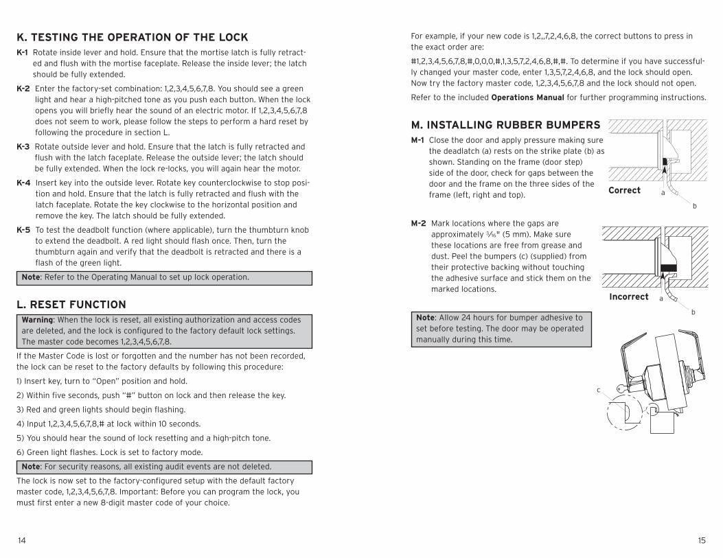
M. INSTALLING RUBBER BUMPERSM-1 Close the door and apply pressure making sure
the deadlatch (a) rests on the strike plate (b) asshown. Standing on the frame (door step)side of the door, check for gaps between thedoor and the frame on the three sides of theframe (left, right and top).
M-2 Mark locations where the gaps areapproximately 3⁄16" (5 mm). Make surethese locations are free from grease anddust. Peel the bumpers (c) (supplied) fromtheir protective backing without touchingthe adhesive surface and stick them on themarked locations.
Note: Allow 24 hours for bumper adhesive toset before testing. The door may be operatedmanually during this time.
K. TESTING THE OPERATION OF THE LOCKK-1 Rotate inside lever and hold. Ensure that the mortise latch is fully retract-
ed and flush with the mortise faceplate. Release the inside lever; the latchshould be fully extended.
K-2 Enter the factory-set combination: 1,2,3,4,5,6,7,8. You should see a greenlight and hear a high-pitched tone as you push each button. When the lockopens you will briefly hear the sound of an electric motor. If 1,2,3,4,5,6,7,8does not seem to work, please follow the steps to perform a hard reset byfollowing the procedure in section L.
K-3 Rotate outside lever and hold. Ensure that the latch is fully retracted andflush with the latch faceplate. Release the outside lever; the latch shouldbe fully extended. When the lock re-locks, you will again hear the motor.
K-4 Insert key into the outside lever. Rotate key counterclockwise to stop posi-tion and hold. Ensure that the latch is fully retracted and flush with thelatch faceplate. Rotate the key clockwise to the horizontal position andremove the key. The latch should be fully extended.
K-5 To test the deadbolt function (where applicable), turn the thumbturn knobto extend the deadbolt. A red light should flash once. Then, turn thethumbturn again and verify that the deadbolt is retracted and there is aflash of the green light.
Note: Refer to the Operating Manual to set up lock operation.
L. RESET FUNCTIONWarning: When the lock is reset, all existing authorization and access codesare deleted, and the lock is configured to the factory default lock settings.The master code becomes 1,2,3,4,5,6,7,8.
If the Master Code is lost or forgotten and the number has not been recorded,the lock can be reset to the factory defaults by following this procedure:
1) Insert key, turn to “Open” position and hold.
2) Within five seconds, push “#” button on lock and then release the key.
3) Red and green lights should begin flashing.
4) Input 1,2,3,4,5,6,7,8,# at lock within 10 seconds.
5) You should hear the sound of lock resetting and a high-pitch tone.
6) Green light flashes. Lock is set to factory mode.
Note: For security reasons, all existing audit events are not deleted.
The lock is now set to the factory-configured setup with the default factorymaster code, 1,2,3,4,5,6,7,8. Important: Before you can program the lock, youmust first enter a new 8-digit master code of your choice.
a
b
Correct
Incorrect
c
a
b