#1 MODEL 810SS MANUAL-2003 - Blizzard Plowslibrary.blizzardplows.com/blizzardplows/pdffiles/2003...
36
2003 Assembly & Operation Manual Blizzard ® Power Plow ® Snowplow Model 810SS BLIZZARD POWER PLOW ® YEARS 1999 2003 to www.blizzardplows.com
-
Upload
hoangquynh -
Category
Documents
-
view
219 -
download
2
Transcript of #1 MODEL 810SS MANUAL-2003 - Blizzard Plowslibrary.blizzardplows.com/blizzardplows/pdffiles/2003...

2003 Assembly & Operation ManualBlizzard® Power Plow® Snowplow
Model 810SS
BLIZZARDPOWER PLOW
®
YEARS1999
2003to
www.blizzardplows.com

i Table of Contents
Table of Contents01 Snowplow Accessories02 Warning!03 Snowplow Operation
Assembly Instructions04 Unpacking & Inspection05 Moldboard Assembly06 A-frame Assembly07 Electrical Assembly - Control Wire Harness08 Testing The Snowplow09 Mounting & Dismounting Instructions
Maintenance & Plow Specifications10 Regular Maintenance11 Storing Your Snowplow12 Plow Specifications
Torque Specifications13 Bolts & Hydraulic Adapters
Plow Diagrams & Part Lists14 Model 810SS Power Plow Snowplow Parts List16 Model 810SS Power Plow Snowplow Assembly Schematic18 Hydraulic Manifold Detail
Electrical Diagrams19 Coil Harness & Hydraulic Manifold Schematic20 Pistol Grip Control Wire Harness Diagram21 Pistol Grip Control Wire Schematic22 Wire Harness Extension (Vehicle Side) Diagram23 Wire Harness Extension (Vehicle Side) Wire Schematic24 Wire Harness Extension (Plow Side) Diagram25 Wire Harness Extension (Plow Side) Wire Schematic26 Coil Wire Harness Diagram27 Coil Wire Harness Wire Schematic28 Auxiliary Control Harness Diagram29 Auxiliary Control Harness Wire Schematic
Troubleshooting30 Troubleshooting Guide
Warranties32 Limited Consumer Warranty33 Commercial Warranty
Introduction
Congratulations on purchasing the mostadvanced all-season skid steer snowplowattachment available! The Blizzard PowerPlow Model 810SS is clearing new trails for innovative design, rugged durability,quality craftsmanship and superior per-formance. Our exclusive products aremanufactured and tested in Michigan’sUpper Peninsula, the snow capital of theMidwest.With an annual snowfall averagingover 250," we couldn’t imagine buildingsnow removal products anywhere else!
Your Blizzard Power Plow is equippedwith versatile features designed for years of dependable service.Twelve-inch expanding wings automatically transform a compact 8' blade into a massive 10' machine. Also, the inde-pendent wings can pivot forward to formour 9'-3" BucketBlade™ position. Now you can carry more snow even further.Turn your Power Plow into an all-seasonskid steer blade with an easy to installoptional trip-lock assembly. This one piece accessory replaces the standard trip springs to provide a rigid gradingblade. Safety features include full mold-board trip action, enclosed hydraulics and automatic cylinder pressure relief.
To ensure years of optimum snowplow performance, review the contents of thismanual. It contains assembly information,detailed diagrams, complete parts listings,maintenance guidelines and trouble-shooting tips.
Should you need additional information,contact your local Blizzard Power PlowDealer. Their knowledgeable staff is well informed on the latest Power Plow information. They are also your sourcefor replacement parts, technical assis-tance and all service repairs.
Comments, suggestions or concerns?Address all correspondence to:
Blizzard CorporationCustomer Service Department95 Airpark BoulevardCalumet, MI 49913

Snowplow Accessories 01
Heavy-Duty 3/8" Wing Cutting Edges with HardwareP/N 61288
Beef-up your Blizzard Power Plowsnowplow with our 3/8" thick wingcutting edges. Made of T1 material,these edges are built to withstandheavy plow use on the roughest
road surfaces. These durable wing edges also provide addedmaterial for protection against sidewalk curb wear. Mounting hardware included.
810SS Trip-Lock Assemblywith HardwareP/N 70028
Turn your Blizzard Power Plowinto an all-season skid steer bladewith an easy to install trip-lockassembly. This one-piece acces-sory replaces the standard trip
springs to provide a rigid grading blade. Now you can level andgrade material in a fraction of the time! Trip-Lock assembly shippedcomplete with mounting hardware.
Auxiliary Control Harness P/N 62162
Integrate all snowplow controls intoyour skid steer using an optionalauxiliary control harness. This 7 ft.braided harness connects easilyto your existing manifold harnesson one end and your skid steer on
the other. Assembly of the harness wiring to your skid steer-spe-cific auxiliary electrical controls required. Electrical connector notprovided with harness. Some connectors available for purchase.
Snowplow AccessoriesAll of the accessories pictured below are currently offered for your snow-plow. See your local authorized Blizzard Dealer for pricing and availability.Visit our web site at www.blizzardplows.com to view new snowplowaccessories and our latest Blizzard snowplow wearables.
Rubber Snow DeflectorP/N 61241
Plow safer and easier with ourcustom rubber snow deflector.This easy-to-install accessorykeeps snow off of your windshieldand in its place—on the ground!Rugged and durable, the 3/8"
thick, 2-ply construction is made to last. The one piece rubberdesign allows for wing clearance and provides optimum snowdeflection. The deflector is shipped with a “Blizzard Power Plow”vinyl decal and complete mounting hardware.
Blizzard Snowplow Touch-Up PaintP/N 61219 (Gloss White)P/N 63073 (Gloss Black)
Putting your snowplow away forthe winter? Have a deep scratchto cover? Clean up your blade andplow parts with our gloss spraypaints. Blizzard snowplow touch-
up paint provides an excellent finish to help keep your snowplowlooking its best. Paint provided in 12 oz. spray cans.

02 Warning!
Warning!Prior to operating your Power Plow snowplow, review the WARNING!label at the passenger’s side rear of the moldboard (shown below).
Note: Read and understand all warnings indicated in this manual priorto operating the snowplow. Warnings and cautions in the manual areindicated by the icons shown to the left.
WARNING:
CAUTION:
Should the WARNING! label or any of the labelsthat came with your snowplow become hard toread or wear off, contact your local authorizedBlizzard dealer for replacements.
Calumet, MI 49913
1. Properly mount the snowplow attachment prior to moving the skid steer.
2. Always inform persons to stand clear of the snowplow and skid steer attachment plates when mounting. Failure to do so may result in serious injury or death.
3. Securely position all mounting levers prior to operating your skid steer attachment.
4. Never use the snowplow attachment to carry people, as a man lift or work platform.
5. Always travel with the wings fully retracted.
6. Do not change the position of the blade while in transit.
7. Always lower the attachment when the skid steer is parked.
8. Never stand, work or reach under lift arms or lift cylinders without an approved liftarm stop installed. Failure to do so may result in serious injury or death.
9. Use caution when plowing with down pressure. The plow attachment can cause thefront wheels on the skid steer to raise.
10. High pressure hydraulic fluid can puncture skin causing serious injury or death.In the event of a hydraulic leak, lower load or relieve hydraulic pressure beforeloosening hydraulic fittings.
If injured, seek emergency medical help immediately.
Blizzard Power Plow snowplow is protected by U.S. Patents 5,899,007 and 5,638,618. Other patents pending.
READOWNER’SMANUAL
THOROUGHLYPRIOR TO
OPERATINGPLOW.
WARNING
WARNING
BLZ 1013

D.
C.
B.
A.
Snowplow Operation 03
Snowplow OperationYour Blizzard Power Plow snowplow is the most advanced and versatilesnowplow on the market. The easy to use controls allow you to automat-ically adjust the plow blade and wings into an infinite number of plowingpositions. Review the illustrations below to determine the best position foryour plowing needs.
A. Compact Position (8' Blade Width)
• Primary position when transporting the snowplow
• For use in heavy snow conditions with poor visibility, initial clearing and tight quarters
• Ideal application: Residential driveways, small roads
B. WidePass™ Position (10' Blade Width)
• Primary position for clearing large surfaces
• For use in light snow conditions with good visibility, final clearing and clean-up
• Ideal application: Large parking lots, widening roadways
C. BucketBlade™ Position (9'-3" Blade Width)
• Primary position for transporting snow
• For use in initial clearing with decent visibility, transporting large volumes of snow, final clean-up
• Ideal application: Roadway intersections
D. WidePass™ Position Angled withWing Forward
• Primary position for accelerated angled plowing
• For use in directional plowing, cornering, diverting snow away from objects or buildings
• Ideal application: Plowing adjacent to buildings,driveway /road intersections

04 Unpacking & Inspection
Assembly InstructionsUnpacking & Inspection
Your Blizzard Power Plow snowplow has been packaged to withstandtransit and weather related damage. Fully inspect all components uponreceipt of your plow. In the event of shipping damage or missing parts,immediately contact our Customer Service Department at 1-888-680-8600.
Begin unpacking and inspection in the following order:
1. Remove the shipping document from the end panel of the pallet wrap.Retain all documentation for your records.
2. All wood framing and polyethylene material should be removed fromthe pallet for easy access to the snowplow.
3. Due to the odd shaped components and size of several assemblyparts, various cable ties and corrugated material are used for scratchresistance and package orientation. Please remove these items priorto assembly.
4. Place the main blade assembly on a flat, level surface.
Once you have inspected all parts and removed all packaging materials,your snowplow is ready to be fully assembled.
Pallet Wrap End Panel
The tear resistant woven polyethylene pallet wrapcontains a moisture barrier to help protect allpackaged components and keep out the mostinclement weather during shipping and storage.The end panel of the pallet cover contains impor-tant information regarding the snowplow modeland the plow’s serial number. Both of these num-bers are given together. The first three digits, andtwo letters, of the number indicated is always theplow model – 810SS and the entire ten digit num-ber make up the serial number. The shipping document is also attached to the end panel. Besure to retain this list for your records.
Snowplow Serial Number
Telephone Number
Dealer/Distributor
Date of Purchase

Moldboard Assembly 05
Moldboard Assembly
1. Begin the moldboard assembly by first removing each dust cap from both of the SLIDE BOX CYLINDERS located at the center/rear of theMOLDBOARD. Attach one 7/16"-20 x 9/16"-18 MALE O.R.B. CON-NECTOR to each of the retract ports (#7 & #10) and one 9/16"-18 x9/16"-18 MALE O.R.B. CONNECTOR to each of the extend ports (#8& #9). Review the diagram below. Note: All of the hydraulic adapterscan be found packaged with the manifold assembly. Reference thetable on page 13 for proper torque specifications.
2. Connect the hoses to each of the hydraulic adapters on the cylinders.Ports #7 & #10 receive a 1/4" x 36" HYDRAULIC HOSE (P/N 60019).Note: Review the label on each hose for the appropriate part number.Ports #8 & #9 receive a 3/8" x 36" HYDRAULIC HOSE (P/N 60224).
3. Next, position the PIVOT BEAM and the A-FRAME, near the mountlocations at the rear of the blade, between the two center support ribs.Place the right and left group of hydraulic hoses (connected to the slidebox cylinders) through the 1-1/2" diameter rubber grommet openingsin the front face of the pivot beam.
4. Position the pivot beam between the two support ribs until the con-necting points on the beam align with those on the plow. Insert one3/4" DIA. x 3" CLEVIS PIN through each mounting hole and securethem with one 1/4" DIA. x 1-1/2" COTTER PIN.
5. Hook each EXTENSION SPRING to the receiving holes located onthe pivot beam and connect the opposite end of the spring to theirrespective SPADE BOLTS. Install the 5/8"-11 x 6-3/8" spade boltsthrough the EXTENSION SPRING MOUNTING ANGLE on the top rearof the blade. Secure each spade bolt by placing one 5/8" flat washeron the bolt and thread one 5/8"-11 nylon insert lock nut. Tighten eachlock nut until a piece of paper can pass between the 3th & 4th coilson the spring.
6. Install the flexible BLADE GUIDES at each end of the moldboard.Insert the 5/16"-18 x 1" hex head cap screw through the holes at thetop of the wing reinforcement rib. Tighten all screws using the nyloninsert lock nuts provided.
Congratulations! You have successfully completed the first stage ofassembly for the Blizzard Power Plow Model 810SS. In the next sectionyou will assemble the A-frame and the components that are attached to it.
Rod
#7
Base
#8 #9
Base
#10
Rod
DRIVER’S SIDE PASSENGER’S SIDE
Male O.R.B. Connector Adapter(Ports #7 & #10)
Male O.R.B. Connector Adapter(Ports #8 & #9)
7/16" 9/16" 9/16" 9/16"
PrintedLabel
All of the hoses shipped with the snowplow con-tain a printed label (with a part number) appliedto the hose. Install the following hoses to theirrespective ports on the manifold:
Hose P/N 60091 Ports #1 & #2Hose P/N 60019 Ports #7 & #10Hose P/N 60224 Ports #8 & #9Note: See diagram on page 6.

06 A-frame Assembly
A-frame Assembly
For your convenience, the MANIFOLD and ANGLE CYLINDERS havebeen secured to the A-FRAME at the factory; however, each contain several components you will need to install.
1. Begin the assembly by first removing the A-FRAME COVER. Removeeach of the 3/8"-16 x 1-1/2" hex cap screws and washers from thecover to gain access to the hydraulic manifold.
2. Each of the 6 HOSE PORTS receive a HYDRAULIC ADAPTER (seeillustrations to the left). Once the adapters have been installed, con-nect the HYDRAULIC HOSES. Route each hose grouping from thepivot beam to the access holes located on the sides of the A-frame.Connect the hydraulic hoses to their respective adapters on the man-ifold. Reference the table on page 13 for proper torque specifications.
Note: All ports are identified by a stamped number on the manifold.Thenumbers also identify the hydraulic functions, which can be referencedon the label under the A-frame cover (shown below).
9/16"
9/16"
90˚ Adjustable Elbow O.R.B. Adapter(Left & Right Angle Cylinders)
9/16" 9/16"
7/16" 9/16"
Male O.R.B. Connector Adapter(Port #1, #2, #8 & #9)
Male O.R.B. Connector Adapter(Port #7 & #10)
Hydraulic Valve & Hose PortIdentification Guide (Model 810SS)
NOTE: Energize the following solenoids for the functions:
1278910
Function
Right Angle - Left CylinderLeft Angle - Right Cylinder
Left Slide Box RetractLeft Slide Box Extend
Right Slide Box ExtendRight Slide Box Retract
Port
Calumet, MI 49913 BLZ 1056
HYDRAULIC HOSES
CV2 CV4 PC
7
8
2
1
10
9
S10 S3 S4 S2RV1 RV4
S9
RV2 RV3
RV5
S1
S5
Wing Pressure Relief Valves
Angle Pressure Relief ValveLeft Wing Pressure ReliefLeft Wing Anti-Cavitation
Right Wing Anti-CavitationRight Wing Pressure Relief
Angle ReliefLeft Wing Check Valve
Left Slide Box Check ValveRight Wing Check Valve
Right Slide Box Check Valve
Right Slide Box RetractRight Slide Box Extend
Angle Left - Right CylinderAngle Right - Left Cylinder
Left Slide Box RetractLeft Slide Box Extend
RV1RV2RV3RV4RV5CV1CV2CV3CV4
S1S2S3S4S9
S10
FunctionValve
RELIEF & CHECK VALVES
NOTE: Check valves CV1 & CV3 are notillustrated. Both valves are located on theopposite side of the manifold in thediagram shown below.
The Hydraulic Valve & Hose Port IdentificationGuide (right) is located under the A-frame cover.
3. Next, remove each dust cap from both of the hydraulic angle cylinderports and attach one 9/16"-18 x 9/16"-18 90˚ ADJUSTABLE ELBOWO.R.B. ADAPTER to each port. Note: The cylinder ports should befacing away from the A-frame. Each adapter should be angled towardthe top of the moldboard. Review the torque specifications chart onpage 13. Connect one 3/8" x 24" hydraulic hose (P/N 60091) to eachangle cylinder adapter.

Electrical Assembly - Control Wire Harness 07
Be careful not to overtighten the hose connections. Complete the hose installation by running each hose through the access holes inthe A-frame to their respective manifold ports.
4. The PRESSURE & TANK HYDRAULIC HOSES attach to the ports onthe side of the manifold labeled “P” and “T”. Verify that the 3/4" x 78"hydraulic hose with the 1-1/16"-12 female swivel is attached to the 1-1/16"-12 x 1-1/16"-12 MALE O.R.B. CONNECTOR ADAPTERlocated in the pressure port (“P”). The 3/4" x 78" hydraulic hose, withthe male O.R.B. 90˚ swivel, connects to the tank port (“T”). Once youhave completed the installation of the hydraulic hoses, begin to installthe wire harness.
When handling the hydraulic manifold DO NOThold the manifold by the wire lead coils. The sole-noid cartridges can bend, causing them to stickwhen activated. Always carry the manifold by thesides of the aluminum block.
Electrical Assembly - Control Wire Harness
1. Begin the installation by connecting the MALE ELECTRIC CONNEC-TOR found on the COIL WIRE HARNESS (on manifold) to the FEMALEELECTRIC CONNECTOR on the WIRE HARNESS EXTENSION(PLOW). Once both connectors are locked together, feed the oppositeend of the wire harness extension through the top access hole (sameas 3/4" tank hydraulic hose) in the A-frame located on the driver’s side.
2. Locate the GROUND END RING TERMINAL on the coil wire harnessand wire harness extension. Using a 3/8"-16 x 1-1/2" hex cap screwand 3/8" tooth lock washer, ground both wires to the A-frame. Securethe wires using a 3/8" top lock nut. Review the diagram below for theproper ground location.
3. Next, connect the MOLDED RUBBER CONNECTOR from the wireharness extension (plow) to the connector on the WIRE HARNESSEXTENSION (VEHICLE). Lock together the remaining male electricconnector on the PISTOL GRIP CONTROL HARNESS to the femaleelectric connector on the wire harness extension (vehicle). Completethe electrical assembly by attaching the BLACK, GROUND wire fromthe wire harness extension to the cab of the skid steer. The PINK/BLACK POWER wire connects to a switched (on and off with ignition) power source with a minimum of 12 volts.
Manifold Mount Holes
There are three sets of holes in the bottom plateon the A-frame. Each set is used for specificmodel year snowplow components. The CLEARanodized manifold (2003) uses the center mosthole and the slotted hole to mount the manifold.The hole opposite from the slotted hole serves asthe location for the ground stud. Use a 3/8"-16 x1-1/2" bolt, tooth lock washer and 3/8"-16 top locknut to secure the electrical grounds to the A-frame.
Hydraulic manifold(clear anodized)mount holes
Hole location for3/8"-16 x 1-1/2"ground bolt
The Model 810SS control wire harness is pack-aged with a stainless steel mount bracket (P/N70040). Use the bracket to secure the wire har-ness extension (vehicle) to the skid steer.Position the bracket in the notch provided on themolded rubber connector and mount it to the skidsteer. Locate the bracket in an accessible locationfor easy on-and-off installation of the harness.

08 Testing The Snowplow
4. Complete the assembly by attaching the A-frame cover. Align theholes in the cover with those on the A-frame and secure it with 3/8"-16 x 1-1/2" hex cap screws and 3/8" washers.
Congratulations! You have just completed building the finest snowplowskid steer attachment available! However, the snowplow’s functions stillneed to be tested.
Testing The Snowplow
1. To test all of the functions on the Power Plow, your snowplow needsto be properly attached to the skid steer. Follow the mounting proce-dure on page 9.
2. Once the skid steer plate and the UNIVERSAL MOUNT PLATE on theA-frame have been locked together (using the locking levers on theskid steer), complete the hydraulic connections with the skid steerturned off. Note: Due to the various make and model skid steer avail-able, hydraulic couplings for the auxiliary hydraulic connections arenot provided. Consult your skid steer’s Operation Manual for theappropriate couplings needed. Once you have identified the appro-priate hydraulic couplings for your skid steer, make the connections toboth of the 3/4" x 78" hydraulic hoses provided. The hydraulic hosewith the female swivel is attached to the male adapter connectorlocated in the pressure port (“P”) on the manifold. The remaininghydraulic hose with the 90˚ swivel is attached to the tank port (“T”).Complete the hydraulic installation by making the appropriate connect-ions at the skid steer.
WARNING: Always use caution when connecting high-pressure hydraulic fittings. Hydraulic fluid under pressurecan puncture skin causing serious injury or death. In theevent of a hydraulic leak, relieve hydraulic pressure beforeloosening fittings. If injured, seek emergency medical helpimmediately.
3. Start the skid steer and begin to initiate the Power Plow’s blade func-tions. Note: Depending on the skid steer model, it may be necessaryto turn on the skid steer’s auxiliary hydraulic switch prior to operatingthe plow. The left switch operates the DRIVER’S SIDE WING. Pushthe switch UP to EXTEND the wing and DOWN to RETRACT thewing. Push the center switch UP to LEFT ANGLE the snowplow andDOWN to RIGHT ANGLE.The right switch operates the PASSENGER’SSIDE WING. Again, pushing up will extend the wing and down willretract the wing. Upon initiating the switches on the pistol grip control,you may notice a plow function is slow or delayed. The hydraulic fluidis filling the cylinders and replacing air in the system. If necessary,monitor the hydraulic fluid level in your skid steer. Also, look for anyleaks around the manifold, hydraulic hoses and all cylinders.
Congratulations on a successful assembly and installation! Once all of theblade functions have been tested, your Blizzard Power Plow is ready foraction. Should you need additional support during a plow assembly, con-tact your local authorized Blizzard dealer.
B CA
810SS Pistol Grip Control Functions
There are three switches that operate all of the810SS Power Plow blade functions:
(A) DRIVE. BOX: UP-Extend, DOWN-Retract(B) ANGLE: UP-Left, DOWN-Right (C) PASS. BOX: UP-Extend, DOWN-Retract
Pistol Grip Control Mount Bracket
The bracket is designed to mount in a variety ofpositions (see hole placement above). Use thehardware provided to secure the bracket to theskid steer.
Position the pistol grip control into the bracketand “twist-lock” it into place. Depending on oper-ator preference, the control can be mounted vertically or horizontally.
Note: Some skid steer models have safetydevices that rotate in front of the operator whenseated. Do not install the mount bracket such thatit interferes with the operation of these devices.

Mounting & Dismounting Instructions 09
Mounting & Dismounting Instructions
Plow AttachmentLever
ReceivingHoles
A
B
BC
SKID STEER MOUNTING &DISMOUNTING INSTRUCTIONS
MOUNTING
1. Position the skid steer close to the snowplow attachment and align the mountpoints on the skid steer plate to those on the plow attachment plate.
2. Tilt the skid steer plate forward and position the top edge of the plate underthe receiving pocket on the top edge of the snowplow attachment plate.CAUTION: Keep fingers away from skid steer mounting points. Slightlyraise the arms on the skid steer and tilt the skid steer plate toward the cab.The snowplow attachment should now be flush with the skid steer mount.
3. Engage both locking levers on the skid steer by rotating each handle 90˚ intoa horizontal position. The attachment is now properly fastened to the skid steer.
4. Proceed to attach both 3/4" diameter hydraulic hoses from the manifold tothe auxiliary hydraulic connections located on the skid steer. Note: Dependingon the skid steer model, it may be necessary to initiate an auxiliary hydraulicswitch on the skid steer prior to operating the plow.
5. Complete the mounting procedure by attaching the electrical connection onthe wire harness to the auxiliary electrical connection on the skid steer.
DISMOUNTING
1. Lower the attachment on a flat, level surface and turn the engine off.
2. Disconnect the electrical connection at the auxiliary power location.
3. Disconnect both 3/4" diameter hydraulic hoses from the auxiliary hydraulicconnectors.
4. Disconnect the snowplow attachment by rotating both of the locking levers90˚ until they are in the vertical position.
5. Start engine and slowly tilt the skid steer plate forward until the top edge ofthe plate clears the plow attachment plate.
6. Back skid steer away slowly – The disconnect procedure is now complete.
WARNING: Read and understand all warning labels priorto operating your skid steer attachment. Failure to followthis instruction may result in serious injury or death.
Skid steer plate attaches under thetop lip of the snowplow attachment.
With the attachment flush to theskid steer plate, engage both lock-ing levers on the skid steer. Rotateeach handle 90˚ into a horizontalposition. The levers will slide throughthe receiving holes in the snowplowattachment plate. The plate is nowsecurely mounted to the skid steer.
Connect both hydraulic hoses & theelectrical harness to the skid steer.
C
B
A
BLZ 1014
Prior to operating your Power Plow, review the Mounting & DismountingInstructions label at the driver’s side rear of the moldboard (shown below).
Should the Mounting & Dismounting Instructionslabel or any of the labels that came with yoursnowplow become hard to read or wear off, contactyour local dealer or call our authorized Blizzarddealer for replacements.

10 Regular Maintenance
Regular MaintenanceYour Blizzard Power Plow snowplow has been designed for years ofrugged, dependable service with low maintenance. To ensure properworking condition, follow the maintenance guidelines below and on thenext page.
CAUTION: Always follow the maintenance guidelines in a timelyfashion. Failure to observe maintenance guidelines may resultin poor snowplow operation, increased component wear orpossibly lead to part failure.
Routinely inspect the following items – perform maintenance as needed:
1. All fasteners, pins, nuts and bolts for tightness. See the recommendedmaximum bolt torque chart on page 13.
2. All hydraulic hoses and hydraulic hose adapters for wear and leaks.See the recommended hydraulic adapter torque values on page 13.
3. All cylinders for leaks; inspect rod ends for corrosion and pitting.
4. Cutting edges and plow shoes for wear. Do not discard plow shoewashers. These should be retained for different shoe adjustments.
5. Clean and lubricate the male and female electric connectors on thepistol grip wire harness periodically. Apply dielectric grease for every25 hours of snowplow use. You may need to grease more frequentlydepending on your plowing environment.
6. Lubricate all pins and bushings to prevent corrosion and to maintainconsistent operation. The inner slide boxes should also be lubricatedto provide free travel. A NLGI Grade 2 multipurpose lithium complexgrease with molybdenum (MPGM) is recommended for lubrication.
7. Clean and cover deep scratches or exposed metal with Blizzard Snow-plow white (P/N 61219) or black (P/N 63073) touch-up paint. Contactyour local Blizzard dealer for availability.
8. Monitor the hydraulic fluid level in your skid steer periodically.
9. Check the trip spring adjustment. Properly adjusted tension will allowa sheet of paper to pass between the 3rd and 4th coils of the spring.
10. Each wing uses one extension spring to help return it from the forwardor scoop position. Adjust the tension on the installed spring as neededor install and optional second extension spring for increased returnspeed.
Maintenance ScheduleMaintenance Performed Date

Storing Your Snowplow 11
Storing Your SnowplowPlacing Your Plow In Storage
1. Position your plow on a flat, level surface for storage. Follow the dis-mounting procedure illustrated on page 9.
2. Pressure wash and dry the entire snowplow prior to placing in storage.
3. Apply a liberal amount of white lithium grease to the male and femaleelectric connectors on the pistol grip wire harness.
4. Lubricate all exposed hydraulic cylinder rod ends with liquid white lithium grease to prevent corrosion.
5. Lubricate all pins and bushings to prevent corrosion and to maintainconsistent operation, including the inner slide boxes. A NLGI Grade 2multipurpose lithium complex grease with molybdenum (MPGM) isrecommended for lubrication.
6. Clean and cover deep scratches or exposed metal with Blizzard Snow-plow white (P/N 61219) or black (P/N 63073) touch-up paint. Contactyour local Blizzard dealer for availability.
7. Change the hydraulic oil fluid in your skid steer as indicated by themaintenance table in your skid steer Owner’s Manual. It is recom-mended that the fluid in the snowplow attachment be replaced annuallyand the hydraulic pump filter on the skid steer be cleaned.
8. Cover the snowplow with a tarp if stored outside. This will protect yourplow from sun fading and inclement weather which can lead toaccelerated corrosion.
Removing Your Plow From Storage
1. Perform all regular maintenance indicated on the previous page.
2. If you have not replaced the hydraulic fluid in the snowplow’s hydraulicsystem, it is strongly encouraged that you do so prior to operating yourplow.
3. Follow the mounting procedure illustrated on page 9.
4. Once the plow has been properly mounted to the skid steer and all electrical connections have been made, initiate all of the functions ofthe snowplow. Monitor the fluid level in the skid steer periodically.
Annual Fluid ReplacementType & Quantity of Fluid Replaced Date
12 Plow Specifications
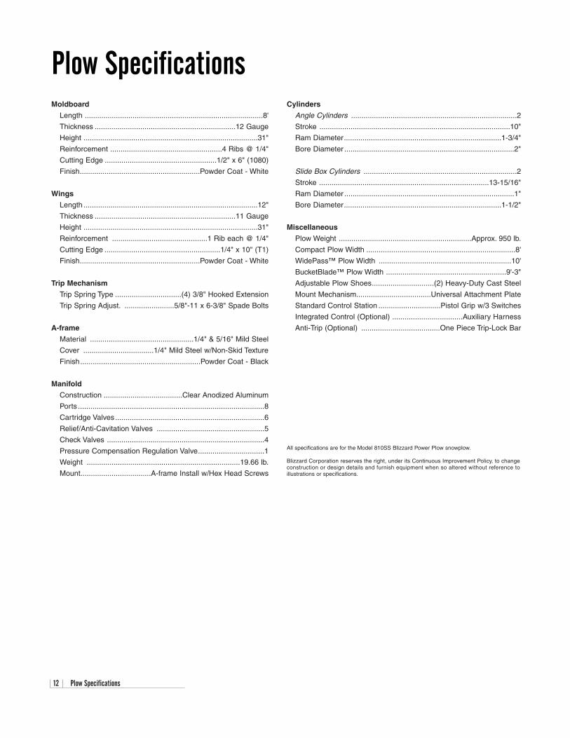
Moldboard
Length ......................................................................................8'
Thickness ....................................................................12 Gauge
Height ....................................................................................31"
Reinforcement ......................................................4 Ribs @ 1/4"
Cutting Edge ......................................................1/2" x 6" (1080)
Finish..........................................................Powder Coat - White
Wings
Length ....................................................................................12"
Thickness ....................................................................11 Gauge
Height ....................................................................................31"
Reinforcement ..............................................1 Rib each @ 1/4"
Cutting Edge ........................................................1/4" x 10" (T1)
Finish..........................................................Powder Coat - White
Trip Mechanism
Trip Spring Type ................................(4) 3/8" Hooked Extension
Trip Spring Adjust. ........................5/8"-11 x 6-3/8" Spade Bolts
A-frame
Material ..................................................1/4" & 5/16" Mild Steel
Cover ..................................1/4" Mild Steel w/Non-Skid Texture
Finish..........................................................Powder Coat - Black
Manifold
Construction ......................................Clear Anodized Aluminum
Ports ..........................................................................................8
Cartridge Valves ........................................................................6
Relief/Anti-Cavitation Valves ....................................................5
Check Valves ............................................................................4
Pressure Compensation Regulation Valve................................1
Weight ..........................................................................19.66 lb.
Mount..................................A-frame Install w/Hex Head Screws
Cylinders
Angle Cylinders ................................................................................2
Stroke ............................................................................................10"
Ram Diameter............................................................................1-3/4"
Bore Diameter ..................................................................................2"
Slide Box Cylinders ..........................................................................2
Stroke ..................................................................................13-15/16"
Ram Diameter ..................................................................................1"
Bore Diameter............................................................................1-1/2"
Miscellaneous
Plow Weight ................................................................Approx. 950 lb.
Compact Plow Width ........................................................................8'
WidePass™ Plow Width ................................................................10'
BucketBlade™ Plow Width ..........................................................9'-3"
Adjustable Plow Shoes..............................(2) Heavy-Duty Cast Steel
Mount Mechanism....................................Universal Attachment Plate
Standard Control Station ..............................Pistol Grip w/3 Switches
Integrated Control (Optional) ..................................Auxiliary Harness
Anti-Trip (Optional) ......................................One Piece Trip-Lock Bar
All specifications are for the Model 810SS Blizzard Power Plow snowplow.
Blizzard Corporation reserves the right, under its Continuous Improvement Policy, to change construction or design details and furnish equipment when so altered without reference to illustrations or specifications.
Plow Specifications

Torque Specifications 13
1. Make sure the tubing and threads are clean.
2. Lubricate the threads with 10W hydraulic oil.
3. Hand tighten the nut/sleeve to appox. 30 in-lbs.
4. Make alignment marks on the nut and fitting.
5. Proceed to tighten to turns or ft-lb values.
6. When fully tightened make a 2nd set of align-ment marks at the fully tightened position.
Note: Torque values specified are for threadslubricated with 10W hydraulic oil.
Sizes -02 through -08 are less tolerant to over-torque abuse. This will reduce the clamping forceresulting in loss of seal and reduction in flow.
37˚ JIC Flare Torque Values
Turns Size ft-lbs min./max. Assembly Steps w/Visual Check
N/A -02 6 - 7N/A -03 8 - 92 -04 11 - 122 -05 14 - 15
1-1/2 -06 18 - 201-1/2 -08 36 - 391-1/2 -10 57 - 631-1/4 -12 79 - 88
1 -14 94 - 1031 -16 108 - 1131 -20 127 - 1331 -24 158 - 1671 -32 245 - 258
Metric Class 8.8 Metric Class 10.9Tightening Torque Tightening Torque
“Lubricated” “Dry” “Lubricated” “Dry”
5 6177 4.63 N-m 6.18 N-m 5 8840 6.63 N-m 8.84 N-m6 8743 7.87 N-m 10.5 N-m 6 12512 11.3 N-m 15.0 N-m7 12570 13.2 N-m 17.6 N-m 7 17990 18.9 N-m 25.2 N-m8 15921 19.1 N-m 25.5 N-m 8 22784 27.3 N-m 36.5 N-m10 25230 37.8 N-m 50.5 N-m 10 36105 54.1 N-m 72.2 N-m12 36670 66.0 N-m 88.0 N-m 12 52475 94.5 N-m 125 N-m14 50025 105 N-m 140 N-m 14 71587 150 N-m 200 N-m16 70650 170 N-m 226 N-m 16 97732 235 N-m 313 N-m18 86400 233 N-m 311 N-m 18 119520 323 N-m 430 N-m20 110250 330 N-m 441 N-m 20 152513 458 N-m 610 N-m
Torque Specifications
SAE J429 - Grade 5 SAE J429 - Grade 8Tightening Torque Tightening Torque
“Lubricated” “Dry” “Lubricated” “Dry”
1/4-20 2,000 75 in-lbs 100 in-lbs 1/4-20 2,850 107 in-lbs 143 in-lbs5/16-18 3,350 157 in-lbs 210 in-lbs 5/16-18 4,700 220 in-lbs 305 in-lbs3/8-16 4,950 23 ft-lbs 31 ft-lbs 3/8-16 6,950 32.5 ft-lbs 44 ft-lbs7/16-14 6,800 37 ft-lbs 50 ft-lbs 7/16-14 9,600 53 ft-lbs 70 ft-lbs1/2-13 9,050 57 ft-lbs 75 ft-lbs 1/2-13 12,800 80 ft-lbs 107 ft-lbs9/16-12 11,600 82 ft-lbs 109 ft-lbs 9/16-12 16,400 115 ft-lbs 154 ft-lbs5/8-11 14,500 113 ft-lbs 151 ft-lbs 5/8-11 20,300 159 ft-lbs 21 ft-lbs3/4-10 21,300 200 ft-lbs 266 ft-lbs 3/4-10 30,100 282 ft-lbs 376 ft-lbs7/8-9 29,435 321 ft-lbs 430 ft-lbs 7/8-9 41,550 454 ft-lbs 606 ft-lbs1-8 38,600 482.5 ft-lbs 640 ft-lbs 1-8 54,540 680 ft-lbs 900 ft-lbs
Clamp Loads(lbs.)
Clamp Loads(lbs.)
NominalThread
Size
NominalThread
Size
Grade Identification Marking for J429 - Grade 5 Bolt• Material: Medium carbon steel: quenched and tempered• Minimum Proof Strength: 85,000 psi• Minimum Tensile Strength: 120,000 psi• Core Hardness Rockwell (min.): C25, (max.): C34• Minimum Yield Strength: 92,000 psi
Grade Identification Marking for J429 - Grade 8 Bolt• Material: Medium carbon alloy steel:quenched and tempered• Minimum Proof Strength: 120,000 psi• Minimum Tensile Strength: 150,000 psi• Core Hardness Rockwell (min.): C33, (max.): C39• Minimum Yield Strength: 130,000 psi
8.8
Clamp Loads(Newton)
Clamp Loads(Newton)
Diameter(millimeters)
Diameter(millimeters)
Grade Identification Marking for Metric - Grade 8.8 Bolt• Material: Medium carbon steel: quenched and tempered• Minimum Proof Strength: 580 MPa• Minimum Tensile Strength: 800 MPa• Core Hardness Rockwell (min.): C22, (max.): C32 • Minimum Yield Strength: 640 MPa
10.9
Grade Identification Marking for Metric - Grade 10.9 Bolt• Material: Low carbon alloy steel: quenched and tempered• Minimum Proof Strength: 830 MPa• Minimum Tensile Strength: 1040 MPa• Core Hardness Rockwell (min.): C32, (max.): C39• Minimum Yield Strength: 940 MPa
O-Ring Boss Torque Values
Size ft-lbs min./max. O-Ring Boss Assembly
-02 6 - 7-03 8 - 10-04 13 - 15-05 17 - 21-06 22 - 25-08 40 - 43-10 43 - 57-12 68 - 75-14 90 - 99-16 112 - 123-20 146 - 200-24 154 - 215-32 218 - 290
1. Verify the port, O-ring, sealing surfaces, and threads areclean and free of damage.
2. Lubricate the threads and the O-ring with 10W hydraulic oil.
3. For an adjustable O.R.B., completely back-off the lock nutand the washer.
4. Hand tighten the fitting until it contacts the port spotface.Point the elbow or tee in the desired direction and hold.
5. Proceed to tighten to the proper specified torque value.
Note: Torque values specified are for threads lubricatedwith 10W hydraulic oil.
Disclaimer: All torque values included in the charts above are advisory only, and their use by anyone is entirely voluntary. Reliance on the contents for any purpose by anyone is the sole risk of that person and Blizzard Corporation is not responsible for any loss, claim or damagesarising therefrom. Blizzard Corporation has made an effort to present the above contents accurately, but we do not guarantee its completeness or validity. This information is subject to change at any time, without notice. Blizzard Corporation makes no representations or warranties,express or implied, in connection with the information.

Ref. Part Qty. Part DescriptionNo. Number
1 52074 1 Moldboard Weldment2 61170 1 Label, WARNING! (BLZ 1013)3 61082 1 Decal, Center Moldboard (BLZ 1000)4 61171 1 Label, Skid Steer Mounting & Dismounting Instructions (BLZ 1014)5 61292 1 Cutting Edge (1080), Moldboard6 61196 7 Bolt, Carriage, 1/2"-13 x 1-1/2" Grade 8 P 7 61365 13 Nut, Flanged Lock, 1/2"-138 51042 1 Wing Weldment, Driver’s Side9 61083 1 Decal, Wing, Driver’s Side (BLZ 1002)
10 51048 1 Cutting Edge Weldment (T1), Wing, Driver’s Side11 50057 1 Slide Box Weldment, Driver’s Side12A 61220 2 Plow Shoe Assembly, Heavy-Duty Cast Iron (8-3/8" Shaft): (1) - 12, 14, (18) - 1312 61102 2 Spacer, 1-1/8" I.D., 1-5/8" O.D. x 1-1/2" YZ13 61101 36 Washer, Flat, 1", 1-1/016" I.D., 1-3/4" O.D. YZ14 61103 2 Pin, Linch, 7/16" x 1-3/4" YZ15 63063 1 Label, Serial Number, Sequentially Numbered (BLZ 1049)16 61383 4 Screw, Hex Head Cap, 5/16"-18 x 2-1/4" Grade 8 YZ17 11871 4 Pin, Slide Box Stop, 1" DIA. x 4-3/4" (with 3/8" DIA. hole)18 61384 4 Nut, Top Lock, 5/16"-18 Grade C Z19A 61049 2 Plow Guide Assembly: (2) - 19 & 2019 61051 4 Screw, Hex Head Cap, 5/16"-18 x 1" Grade 5 Z20 61052 4 Nut, Nylon Insert Lock, 5/16"-18 Z21 51043 1 Wing Weldment, Passenger’s Side22 61084 1 Decal, Wing, Passenger’s Side (BLZ 1001)23 51047 1 Cutting Edge Weldment (T1), Wing, Passenger’s Side24 61418 2 Bolt, Carriage, 1/2"-13 x 3-1/2" Grade 8 P25 61419 2 Bolt, Carriage, 1/2"-13 x 4-1/2" Grade 8 P26 61361 2 Bolt, Carriage, 1/2"-13 x 5-1/2" Grade 8 P27 50058 1 Slide Box Weldment, Passenger’s Side28 61416 2 Bolt, Spade, 5/8"-11 x 7-3/8" Grade 8 Z29 61398 2 Spring, Extension, 13" O.A.L. x 2" O.D. x 5/16"30 61385 2 Pin, Clevis, 5/8" DIA. x 3" YZ31 61028 2 Pin, Spring, 1/4" DIA. x 1-1/4"32 51009 2 Pin, Wing / Slide Box Pivot, 3/4" DIA. x 9"33 61425 2 Plug, 2-51/64" O.D., 2-9/32" I.D. x 1/2" Black Polyethylene34 14622 2 Hydraulic Cylinder, Slide Box Extend/Retract35 61063 2 Nut, Top Lock, 5/8"-11 Grade C Z36 60007 6 Hydraulic Adapter, 9/16"-18 x 9/16"-18 Male O.R.B. Connector37 60224 2 Hydraulic Hose (Ports #8 & #9), 3/8" x 36" - Slide Box Extend38 60003 4 Hydraulic Adapter, 7/16"-20 x 9/16"-18 Male O.R.B. Connector39 60019 2 Hydraulic Hose (Ports #7 & #10), 1/4" x 36" - Slide Box Retract40 61198 2 Cap, 5/8" I.D., 3/4" O.D. x 1", Black Vinyl41 11989 2 Pin, Hydraulic Cylinder Base End, 5/8" DIA. x 11-1/2" (with 1/4" DIA. hole) - Slide Box Extend/Retract42 61030 2 Pin, Hair Cotter, 1/8" DIA. x 2-5/8" Z43 61099 4 Spring, Extension, 15-1/4" O.A.L. x 2-3/8" O.D. x 3/8"44 61187 4 Bolt, Spade, 5/8"-11 x 6-3/8" Grade 8 Z45 61064 4 Washer, SAE Mil Carb High-Strength, 5/8", 1-5/16" O.D., 21/32" I.D. YZ46 61188 4 Nut, Nylon Insert Lock, 5/8"-11 Type NE
47 41041 1 Pivot Beam Weldment48 50069 2 Pin, Clevis, 3/4" DIA. x 3" YZ49 61357 6 Pin, Cotter, 1/4" x 1-1/2" Z50 41051 4 Pin, Clevis, 3/4" DIA. x 5" YZ51 61330 1 Screw, Hex Head Cap, 1"-8 x 9" (with 7-3/4" Shank) Grade 8 P52 61008 1 Nut, Top Lock, 1"-8 Grade C Z53 61217 4 Grommet, 1-1/2" I.D., 2-1/8" O.D. Black Rubber, 60 Durometer54 60029 2 Hydraulic Cylinder, Plow Angle55 60091 2 Hydraulic Hose (Ports #1 & #2), 3/8" x 24" - Plow Angle56 60005 2 Hydraulic Adapter, 9/16"-18 x 9/16"-18 90˚ Adjustable Elbow O.R.B.57A 70045 1 A-frame Cover Assembly: (1) - 57-5957 70041 1 Cover, A-frame 58 63068 1 Label, Sequence Valve & Hydraulic Hose Identification Guide (BLZ 1052) 59 70021 1 Grip, Non-skid, Rubber 60 61016 11 Washer, SAE Mil-Carb High-Strength, 3/8", 13/16" O.D., 13/32" I.D., YZ 61 61328 8 Screw, Hex Head Cap, 3/8"-16 x 1-1/2" Grade 8 YZ62A 70044 1 A-frame Assembly: (1) - 57A, 62, 69, (2) - 67, (7) - 60, 61, 6862 70043 1 A-frame Weldment 63 61313 2 Screw, Hex Head Cap, 3/8"-16 x 3-3/4" Grade 8 YZ 64 61307 1 Washer, Internal/External Tooth Lock, 3/8" 65 61034 3 Nut, Top Lock, 3/8"-16 Grade C Z 66 61222 2 Washer, Split Lock, 3/8" YZ High-Alloy
Note: The reference numbers listedidentify parts shown in the illustrationon pages 16-18. These numbers arespecific to these illustrations only anddo not correspond with other diagramsin the manual. Always review the partnumber given for proper componentidentification.
M O D E L 8 1 0 S S PA R T S L I S T
Moldboard & Wing Assembly Parts
Pivot Beam & A-frame Assembly Parts
14 Parts List (1 of 2)

Parts List (2 of 2) 15
Ref. Part Qty. Part DescriptionNo. Number
67 61366 2 Grommet, 1-15/16" I.D., 2-5/8" O.D. Black Rubber, 60 Durometer68 61275 7 U-Nut, 3/8"-1669 61085 1 Decal, Blizzard Snowplows, 2-1/4" x 13-7/8" (BLZ 1003)
70 60086 1 Hydraulic Hose, 3/4" x 78" - 1-1/16"-12 Female Swivel / 3/4"-14 Male Pipe Str.aight, Pressure Port “P”71 60087 1 Hydraulic Hose, 3/4" x 78" - 1-1/16"-12 Male O.R.B.90˚ Swivel/ 3/4"-14 Male Pipe Straight, Tank Port “T”72A 60268 1 Hydraulic Manifold Assembly: (1) - 72-74, 78A, 81, 82, (2) - 38, 77, 83, 84, 60322, (4) - 36, 75, 76, (5) - 7972 60267 1 Manifold Block (with Cross Port Relief) Clear Anodized Aluminum (30102904) 73 60089 1 Hydraulic Adapter, 1-1/16"-12 x 1-1/16"-12 Male O.R.B. Connector74 60183 1 Valve, Pressure Compensation Regulation (88400015)75 60225 4 Valve, Check, 50 PSI (86020028)76 60166 4 Valve, Spool, Three-Way, Two Position (86020195 w/o screen)77 60278 2 Valve, Relief, 1700 PSI (85020411 tamper proof)78A 62161 1 Coil Harness Assembly: (1) - 62045, 62118, (2) - 80, (3) - 62116, (5) - 78, (7) - 62096 & 62097 78 62163 5 Coil, PDL, 12V DC (38400066)79 60052 5 Nut, Hex Jam, 1/2"-20 YZ80 62164 2 Coil, LDL, 12V DC (63900506)81 60321 1 Valve, Spool, Four-Way, Three Position (85020081 w/o screen)82 60168 1 Valve, Relief, 3000 PSI (85020340)83 60049 2 Plug, #4 SAE (61010016)84 60279 2 Valve, Relief, 1500 PSI (85020410 tamper proof)85 60320 1 Valve, Spool, N.O. (86020193)
N/A 60322 2 Piston Assembly (34952125)
86A 62131 1 Pistol Grip Control Wire Harness Assembly: (1) - 86, 87 & 62132-62135 86 62082 1 Wire Harness, Pistol Grip
N/A 62132 1 Wire Harness Extension, Vehicle SideN/A 62133 1 Weather Cap, Molded Rubber, Female (Wire Harness Extension, Vehicle Side)87 70040 1 Mount Bracket, Wire Harness Extension, Vehicle Side
N/A 62134 1 Wire Harness Extension, Plow SideN/A 62135 1 Weather Cap, Molded Rubber, Male (Wire Harness Extension, Plow Side)N/A 62045 2 Connector, Electric, Male, Plastic N/A 62097 17 Terminal, Male (18-16 AWG)N/A 62096 35 Seal, Cable, Silicone, Orange (18 AWG)N/A 62116 5 Plug, Cavity, Silicone, White (18-16 AWG)N/A 62046 2 Connector, Electric, Female, PlasticN/A 62100 2 Terminal, Ring, #10 (22-18 AWG)N/A 62093 18 Terminal, Female (18-16 AWG)N/A 62118 1 Terminal, End Ring, 3/8" I.D. Zinc, 6 Gauge (Coil Harness)N/A 62072 1 Terminal, End Ring, 3/8" I.D. Copper, 4 Gauge (Wire Harness Extension, Plow Side)88A 70048 1 Pistol Grip Control Mount Bracket Assembly: (1) - 88, (2) - 60, 89 & 9088 70049 1 Mount Bracket, Pistol Grip Control 89 61214 2 Screw, Hex Head Cap, 3/8"-16 x 1-1/4" Grade 8 YZ 90 61014 2 Nut, Jam Nylon Insert Lock, 3/8"-16 Z, Type NTE
N/A 61277 1 Kit, Hardware, Snowplow Assembly Parts: (1) - 61, 64, 65, (2) - 48, 49, (4) - 44-46N/A 60319 1 Kit, Hydraulic Adapter: (2) - 56, (4) - 38, (6) - 36 N/A 60323 1 Kit, Hydraulic Hose: (1) - 70 & 71, (2) - 37, 39 & 55N/A 61430 1 Kit, Hardware, Moldboard Cutting Edge: (7) - 6 & 7N/A 52067 1 Kit, Cutting Edge, Moldboard w/Hardware: (1) - 5, 61430N/A 61431 1 Kit, Hardware, Wing Cutting Edge: (1) - 24-26, (3) - 7N/A 51104 1 Kit, Cutting Edges, Wing w/Hardware: (1) - 8, 21, (2) - 61431 N/A 61321 1 Kit, Moldboard & Wing Cutting Edges w/Hardware: (1) - 52067, 51104
M O D E L 8 1 0 S S PA R T S L I S T
Pivot Beam & A-frame Assembly Parts (Continued)
Hydraulic Manifold Assembly Parts
Pistol Grip Control Wire Harness Assembly Parts
Miscellaneous Assembly Parts
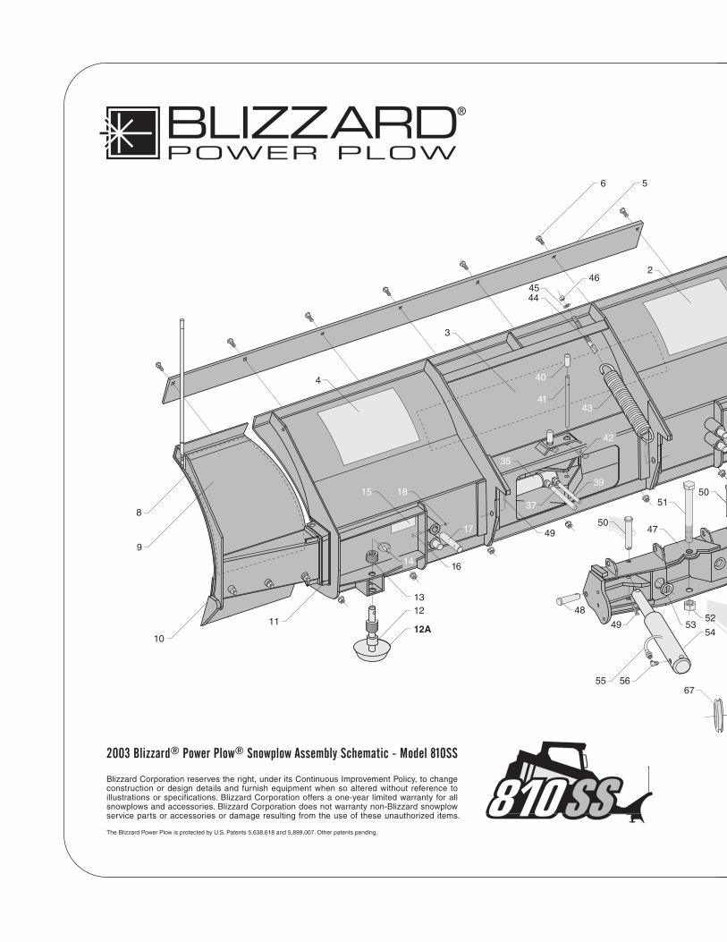
2003 Blizzard® Power Plow® Snowplow Assembly Schematic - Model 810SS
Blizzard Corporation reserves the right, under its Continuous Improvement Policy, to changeconstruction or design details and furnish equipment when so altered without reference toillustrations or specifications. Blizzard Corporation offers a one-year limited warranty for allsnowplows and accessories. Blizzard Corporation does not warranty non-Blizzard snowplowservice parts or accessories or damage resulting from the use of these unauthorized items.
The Blizzard Power Plow is protected by U.S. Patents 5,638,618 and 5,899,007. Other patents pending.
67
2
3
4
6 5
8
9
11
1012A
1213
14 16
17
181537
39
35
40
41
42
43
4445
46
4749
49
48
50
50
52
51
54
55 56
53

63
60
61
86A
86
49
72A - SEE DETAIL ON PAGE 18.
50
49
50
71
69
6360
6465
66
62A
62
57A
59
5758
61
60
68
6588
89
60
90
88A
87
1
7
38
39
36
37
48
54
56
31
26
23
25 24
20
21
22
19
19A
7
28
35
27
30
29
3233
34
55
70
49
50
7
4

18 Diagram - Hydraulic Manifold Detail
7273
74
75 3638
75
7676
7676
77
77
78A 78 78
78
7878
79
79
79
80
8182
83
84
84
85

Coil Harness/Hydraulic Manifold Schematic 19
MODEL 810SS COIL HARNESS WIRE SCHEMATIC (2003)
MODEL 810SS HYDRAULIC MANIFOLD SCHEMATIC (2003)
S10S4
S9 S1
ABCDEFGHJK
CONNECTS TO C3SEE SCHEMATIC ON PAGE 24.
S4
S3
S9
S10
S1
S2
N/A
N/A
S5
N/A
S3S2
S5
RV11700 PSI
8 7
RV21500 PSI
LEFT SLIDE BOX
RIGHT ANGLE
LEFT ANGLE1 2 9 10
CV150 PSI
CV250 PSI
RV41700 PSI
RV31500 PSI
CV350 PSI
CV450 PSI
RIGHT SLIDE BOX
S10 S2 S1S9
3000 PSIRV5
S3 S4
.052
.110
P T
PC50 PSI
S5

20 Diagram - Pistol Grip Control Wire Harness
NO
TE
: NO
NU
MB
ER
S O
N S
WIT
CH
(US
E T
HIS
CH
AR
T T
O F
IND
TO
P)
PIN
NO
.C
OLO
RA
WG
LEN
GT
H
1B
RO
WN
186"
2B
LUE
/BLA
CK
1884
"3
PIN
K/B
LAC
K18
6"4
PIN
K/B
LAC
K18
6"5
BR
OW
N18
6"6
BLU
E/W
HIT
E18
84"
NO
TE
: NO
NU
MB
ER
S O
N S
WIT
CH
(US
E T
HIS
CH
AR
T T
O F
IND
TO
P)
PIN
NO
.C
OLO
RA
WG
LEN
GT
H
1B
RO
WN
186"
2G
RE
EN
1884
"3
PIN
K/B
LAC
K18
6"4
PIN
K/B
LAC
K18
6"5
BR
OW
N18
6"6
BLU
E18
84"
810S
S P
ISTO
L G
RIP
CO
NT
RO
LW
IRE
HA
RN
ES
S (
2003
)P
/N 6
2082
NO
T D
RA
WN
TO
SC
ALE
UN
LES
S O
TH
ER
WIS
E S
PE
CIF
IED
ALL
DIM
EN
SIO
NS
IN IN
CH
ES
AB
CE
D
FG
HK
J
EN
D V
IEW
LOO
KIN
G A
T C
ON
NE
CTO
R
PAC
KA
RD
GT
280
ELE
CT
RIC
CO
NN
EC
TOR
PIN
C
OLO
RF
UN
CT
ION
AW
GN
O.
AP
INK
/BLA
CK
PO
WE
R18
BB
RO
WN
PU
MP
SO
LEN
OID
18C
BLA
CK
GR
OU
ND
(JU
MP
ER
)18
DB
LAC
KG
RO
UN
D (
JUM
PE
R)
18E
GR
EE
NR
IGH
T A
NG
LE18
FB
LUE
LEF
T A
NG
LE18
GB
LUE
/BLA
CK
DR
IVE
. SLI
DE
BO
X R
ET.
18H
BLU
E/W
HIT
ED
RIV
E. S
LID
E B
OX
EX
T.18
JR
ED
/BLA
CK
PAS
S. S
LID
E B
OX
RE
T.18
KR
ED
/WH
ITE
PAS
S. S
LID
E B
OX
EX
T.18
(JU
MP
ER
)
DR
IVE
. SLI
DE
BO
XE
XT
EN
D (
UP
)R
ET
RA
CT
(D
OW
N)
PLO
W A
NG
LELE
FT
(U
P)
RIG
HT
(D
OW
N)
PAS
S. S
LID
E B
OX
EX
TE
ND
(U
P)
RE
TR
AC
T (
DO
WN
)
87"
JAC
KE
T M
ATE
RIA
LB
LAC
K N
YLO
N B
RA
ID
6"1"
LOC
ATIO
N W
HE
RE
BLA
CK
(JU
MP
ER
)W
IRE
RE
TU
RN
STO
CO
NN
EC
TOR
HE
AT A
ND
CA
PB
RA
IDIN
G E
ND
PLA
ST
IC E
LEC
TR
IC C
ON
NE
CT
OR
- M
ALE
(P
/N 6
2045
)S
ILIC
ON
E R
UB
BE
R C
AB
LE S
EA
L (1
8 A
WG
) -
P/N
620
96M
ALE
TE
RM
INA
L (1
8-16
AW
G)
- P
/N 6
2097
C1
CO
NN
EC
TS
TO
C2
ON
PA
GE
22.
BA
CK
VIE
WO
F S
WIT
H #
1
NO
TE
: ALL
PIN
K/B
LAC
K S
PLI
CE
TO
GE
TH
ER
& A
LL B
RO
WN
SP
LIC
E T
OG
ET
HE
R
SW
ITC
H #
1
NO
TE
: NO
NU
MB
ER
S O
N S
WIT
CH
(US
E T
HIS
CH
AR
T T
O F
IND
TO
P)
PIN
NO
.C
OLO
RA
WG
LEN
GT
H
1B
RO
WN
186"
2R
ED
/BLA
CK
1884
"3
PIN
K/B
LAC
K18
6"4
PIN
K/B
LAC
K18
6"5
BR
OW
N18
6"6
RE
D/W
HIT
E18
84"
SW
ITC
H #
2S
WIT
CH
#3
1 3 5
2 4 6
TOP
1 3 5
2 4 6
TOP
1 3 5
2 4 6TOP
BA
CK
VIE
WO
F S
WIT
H #
2B
AC
K V
IEW
OF
SW
ITH
#3
LOC
ATIO
N O
FB
RO
WN
WIR
ES
PLI
CE
BA
CK
BR
AID
ING
CAT
CH
ST
RA
INR
ELI
EF
TU
BE
LOC
ATIO
N O
FP
INK
/BLA
CK
WIR
E S
PLI
CE

Pistol Grip Control Harness Wire Schematic 21
810S
S P
ISTO
L G
RIP
CO
NT
RO
L W
IRE
SC
HE
MA
TIC
(20
03)
DR
IVE
. SID
E R
ET
RA
CT
DR
IVE
. SID
E E
XT
EN
DS
WIT
CH
#3
BR
OW
NB
LUE
/BLA
CK
BLU
E/W
HIT
EG
RE
EN
RE
D/B
LAC
KB
LUE
RE
D/W
HIT
EB
LAC
KB
LAC
KP
INK
/BLA
CK
LEF
T A
NG
LER
IGH
T A
NG
LE
PAS
S. S
IDE
EX
TE
ND
PAS
S. S
IDE
RE
TR
AC
T
SW
ITC
H #
2
SW
ITC
H #
1
C1

22 Diagram - Wire Harness Extension (Vehicle)
810S
S W
IRE
HA
RN
ES
S E
XT
EN
SIO
NV
EH
ICL
E S
IDE
(20
03)
P/N
621
32
NO
T D
RA
WN
TO
SC
ALE
UN
LES
S O
TH
ER
WIS
E S
PE
CIF
IED
ALL
DIM
EN
SIO
NS
IN IN
CH
ES
MO
LDE
D R
UB
BE
R C
ON
NE
CTO
R
PAC
KA
RD
GT
280
ELE
CT
RIC
CO
NN
EC
TOR
PIN
C
OLO
RF
UN
CT
ION
AW
GN
O.
AP
INK
/BLA
CK
PO
WE
R (
PO
SIT
IVE
)18
BB
RO
WN
PU
MP
SO
LEN
OID
18C
BLA
CK
GR
OU
ND
(N
EG
ATIV
E)
18D
BLA
CK
GR
OU
ND
18E
GR
EE
NR
IGH
T A
NG
LE18
FB
LUE
LEF
T A
NG
LE18
GB
LUE
/BLA
CK
DR
IVE
. SLI
DE
BO
X R
ET.
18H
BLU
E/W
HIT
ED
RIV
E. S
LID
E B
OX
EX
T.18
JR
ED
/BLA
CK
PAS
S. S
LID
E B
OX
RE
T.18
KR
ED
/WH
ITE
PA
SS
. SLI
DE
BO
X E
XT
.18
EN
D V
IEW
LOO
KIN
G A
T C
ON
NE
CTO
R
AB
ED
C
KJ
HG
F
PLA
ST
IC E
LEC
TR
IC C
ON
NE
CT
OR
-F
EM
ALE
(P
/N 6
2046
)S
ILIC
ON
E R
UB
BE
R C
AB
LE S
EA
L (1
8 A
WG
) -
P/N
620
96F
EM
ALE
TE
RM
INA
L (1
8-16
AW
G)
- P
/N 6
2093
C2
CO
NN
EC
TS
TO
C1
ON
PA
GE
20.
M1
CO
NN
EC
TS
TO
M2
ON
PA
GE
24.
EN
D V
IEW
LOO
KIN
G A
T C
ON
NE
CTO
R
43
1
98
1014
13
2 7 12116
5
BLI
ZZ
AR
D P
LUG
(S
QU
AR
E)
PIN
C
OLO
RF
UN
CT
ION
AW
GN
O.
BLA
CK
GR
OU
ND
18N
/AN
/AN
/AN
/AN
/AN
/AN
/AN
/AN
/A3
GR
EE
NR
IGH
T A
NG
LE18
4B
LUE
LEF
T A
NG
LE18
5N
/AN
/AN
/A6
N/A
N/A
N/A
7N
/AN
/AN
/A8
RE
D/B
LAC
KPA
SS
. SID
E S
LID
E B
OX
RE
T.18
9B
LUE
/BLA
CK
DR
IVE
. SID
E S
LID
E B
OX
RE
T.18
10B
RO
WN
PU
MP
SO
LEN
OID
1811
N/A
N/A
N/A
12N
/AN
/AN
/A13
RE
D/W
HIT
EPA
SS
. SID
E S
LID
E B
OX
EX
T.18
14B
LUE
/WH
ITE
DR
IVE
. SID
E S
LID
E B
OX
EX
T.18
1 2
JAC
KE
T M
ATE
RIA
LB
LAC
K N
YLO
N B
RA
ID
240"
60"
BLA
CK
(N
EG
ATIV
E)
PIN
K/B
LAC
K (
PO
SIT
IVE
)#1
0 R
ING
TE
RM
INA
LS(2
2-18
AW
G)
- P
/N 6
2100
2"1"
HE
AT A
ND
CA
PB
RA
IDIN
G E
ND
1/2"
RE
VE
RS
EB
RA
IDIN
G
MO
LDE
D R
UB
BE
R W
EAT
HE
R C
AP
- F
EM
ALE
(P/N
621
33)

Wire Harness Extention (Vehicle) Wire Schematic 23
810S
S W
IRE
HA
RN
ES
S E
XT
EN
SIO
N (
VE
HIC
LE
) WIR
E S
CH
EM
AT
IC (
2003
)
BR
OW
N
C2
M1
BLU
E/B
LAC
KB
LUE
/WH
ITE
GR
EE
NR
ED
/BLA
CK
BLU
ER
ED
/WH
ITE
BLA
CK
BLA
CK
PIN
K/B
LAC
K

24 Diagram - Wire Harness Extension (Plow)
810S
S W
IRE
HA
RN
ES
S E
XT
EN
SIO
NP
LO
W S
IDE
(20
03)
P/N
621
34
NO
T D
RA
WN
TO
SC
ALE
UN
LES
S O
TH
ER
WIS
E S
PE
CIF
IED
PLA
ST
IC E
LEC
TR
IC C
ON
NE
CT
OR
-F
EM
ALE
(P
/N 6
2046
)S
ILIC
ON
E R
UB
BE
R C
AB
LE S
EA
L (1
8 A
WG
) -
P/N
620
96F
EM
ALE
TE
RM
INA
L (1
8-16
AW
G)
- P
/N 6
2093
PAC
KA
RD
GT
280
ELE
CT
RIC
CO
NN
EC
TOR
PIN
C
OLO
RF
UN
CT
ION
AW
GN
O.
AN
/AN
/AN
/AB
BR
OW
NP
UM
P S
OLE
NO
ID18
CN
/AN
/AN
/AD
BLA
CK
GR
OU
ND
18E
GR
EE
NR
IGH
T A
NG
LE18
FB
LUE
LEF
T A
NG
LE18
GB
LUE
/BLA
CK
DR
IVE
. SLI
DE
BO
X R
ET.
18H
BLU
E/W
HIT
ED
RIV
E. S
LID
E B
OX
EX
T.18
JR
ED
/BLA
CK
PAS
S. S
LID
E B
OX
RE
T.18
KR
ED
/WH
ITE
PA
SS
. SLI
DE
BO
X E
XT
.18
EN
D V
IEW
LOO
KIN
G A
T C
ON
NE
CTO
R
AB
ED
C
KJ
HG
F
MO
LDE
D R
UB
BE
R C
ON
NE
CT
OR
M2
CO
NN
EC
TS
TO
M1
ON
PA
GE
22.
C3
CO
NN
EC
TS
TO
C4
ON
PA
GE
26.
BLI
ZZ
AR
D P
LUG
(S
QU
AR
E)
PIN
C
OLO
RF
UN
CT
ION
AW
GN
O.
BLA
CK
GR
OU
ND
18N
/AN
/AN
/AN
/AN
/AN
/AN
/AN
/AN
/A3
GR
EE
NR
IGH
T A
NG
LE18
4B
LUE
LEF
T A
NG
LE18
5N
/AN
/AN
/A6
N/A
N/A
N/A
7N
/AN
/AN
/A8
RE
D/B
LAC
KPA
SS
. SID
E S
LID
E B
OX
RE
T.18
9B
LUE
/BLA
CK
DR
IVE
. SID
E S
LID
E B
OX
RE
T.18
10B
RO
WN
PU
MP
SO
LEN
OID
1811
N/A
N/A
N/A
12N
/AN
/AN
/A13
RE
D/W
HIT
EPA
SS
. SID
E S
LID
E B
OX
EX
T.18
14B
LUE
/WH
ITE
DR
IVE
. SID
E S
LID
E B
OX
EX
T.18
1 2
JAC
KE
T M
ATE
RIA
LB
LAC
K N
YLO
N B
RA
ID 66"
HE
AT A
ND
CA
PB
RA
IDIN
G E
ND
HE
AT A
ND
CA
PB
RA
IDIN
G E
ND
12"
36"
BLA
CK
3/8"
EN
D R
ING
TE
RM
INA
LP
/N 6
2072
7 12116
5
21
43 8
9
1013
14
EN
D V
IEW
LOO
KIN
G A
T C
ON
NE
CTO
R
MO
LDE
D R
UB
BE
R W
EAT
HE
R C
AP
- M
ALE
(P/N
621
35)

Wire Harness Extension (Plow) Wire Schematic 25
810S
S W
IRE
HA
RN
ES
S E
XT
EN
SIO
N (
PL
OW
) WIR
E S
CH
EM
AT
IC (
2003
)
BR
OW
N
M2
C3
BLU
E/B
LAC
KB
LUE
/WH
ITE
GR
EE
NR
ED
/BLA
CK
BLU
ER
ED
/WH
ITE
BLA
CK
BLA
CK

26 Diagram - Coil Wire Harness
810S
S C
OIL
WIR
E H
AR
NE
SS
(20
03)
P/N
621
61
NO
T D
RA
WN
TO
SC
ALE
UN
LES
S O
TH
ER
WIS
E S
PE
CIF
IED
ALL
DIM
EN
SIO
NS
IN IN
CH
ES
AB
CE
D
FG
HK
J
EN
D V
IEW
LOO
KIN
G A
T C
ON
NE
CTO
R
PAC
KA
RD
GT
280
ELE
CT
RIC
CO
NN
EC
TOR
PIN
C
OLO
RF
UN
CT
ION
AW
GN
O.
AN
/AN
/AN
/AB
BR
OW
NP
UM
P S
OLE
NO
ID18
CN
/AN
/AN
/AD
N/A
N/A
N/A
EG
RE
EN
RIG
HT
AN
GLE
18F
BLU
ELE
FT
AN
GLE
18G
BLU
E/B
LAC
KD
RIV
E. S
LID
E B
OX
RE
T.18
HB
LUE
/WH
ITE
DR
IVE
. SLI
DE
BO
X E
XT.
18J
RE
D/B
LAC
KPA
SS
. SLI
DE
BO
X R
ET.
18K
RE
D/W
HIT
EP
AS
S. S
LID
E B
OX
EX
T.
18
C4
CO
NN
EC
TS
TO
C3
ON
PA
GE
24.
PLA
ST
IC E
LEC
TR
IC C
ON
NE
CT
OR
- M
ALE
(P
/N 6
2045
)S
ILIC
ON
E R
UB
BE
R C
AB
LE S
EA
L (1
8 A
WG
) -
P/N
620
96M
ALE
TE
RM
INA
L (1
8-16
AW
G)
- P
/N 6
2097
CO
ILS
-12V
DC
PD
L-P
/N 6
2163
LDL-
P/N
621
64
BLU
E/B
LAC
K
GR
OU
ND
BLU
E/W
HIT
E
GR
OU
ND
RE
D/W
HIT
E
GR
OU
ND
S9
DR
IVE
R’S
SID
ES
LID
E B
OX
RE
TR
AC
T
S10
DR
IVE
R’S
SID
ES
LID
E B
OX
EX
TE
ND
GR
EE
N
GR
OU
ND
S4
RIG
HT
AN
GLE
RE
D/B
LAC
K
GR
OU
ND
S1
PAS
SE
NG
ER
’S S
IDE
SLI
DE
BO
X R
ET
RA
CT
S2
PAS
SE
NG
ER
’S S
IDE
SLI
DE
BO
X E
XT
EN
D
STA
MP
ING
ON
MA
NIF
OLD
3/8"
EN
D R
ING
TE
RM
INA
LP
/N 6
2118
BR
OW
N
GR
OU
ND
S5
PU
MP
SO
LEN
OID
BLU
E
GR
OU
ND
S3
LEF
T A
NG
LE
8"
15"

Coil Wire Harness Wire Schematic 27
810S
S C
OIL
HA
RN
ES
S W
IRE
SC
HE
MA
TIC
(20
03)
BR
OW
N
C4
BLU
E/B
LAC
KB
LUE
/WH
ITE
BLU
EG
RE
EN
RE
D/B
LAC
KR
ED
/WH
ITE
BLA
CK
DR
IVE
. SID
E R
ET
RA
CT
GR
OU
ND
DR
IVE
. SID
E E
XT
EN
DG
RO
UN
D
PAS
S. S
IDE
EX
TE
ND
GR
OU
ND
S9
S10
RIG
HT
AN
GLE
GR
OU
ND
S4
S2
PU
MP
SO
LEN
OID
GR
OU
ND
S5
LEF
T A
NG
LEG
RO
UN
D
S3
PAS
S. S
IDE
RE
TR
AC
TG
RO
UN
D
S1

28 Diagram - Auxiliary Control Harness
810S
S A
UX
ILIA
RY
CO
NT
RO
L H
AR
NE
SS
(20
03)
WIT
H IN
TE
RN
AL
DIO
DE
SP
/N 6
2162
NO
T D
RA
WN
TO
SC
ALE
UN
LES
S O
TH
ER
WIS
E S
PE
CIF
IED
ALL
DIM
EN
SIO
NS
IN IN
CH
ES
PLA
ST
IC E
LEC
TR
IC C
ON
NE
CT
OR
-F
EM
ALE
(P
/N 6
2046
)S
ILIC
ON
E R
UB
BE
R C
AB
LE S
EA
L (1
8 A
WG
) -
P/N
620
96F
EM
ALE
TE
RM
INA
L (1
8-16
AW
G)
- P
/N 6
2093
PAC
KA
RD
GT
280
ELE
CT
RIC
CO
NN
EC
TOR
PIN
C
OLO
RF
UN
CT
ION
AW
GN
O.
AN
/AN
/AN
/AB
BR
OW
NP
UM
P S
OLE
NO
ID18
CN
/AN
/AN
/AD
BLA
CK
GR
OU
ND
18E
GR
EE
NR
IGH
T A
NG
LE18
FB
LUE
LEF
T A
NG
LE18
GB
LUE
/BLA
CK
DR
IVE
. SLI
DE
BO
X R
ET.
18H
BLU
E/W
HIT
ED
RIV
E. S
LID
E B
OX
EX
T.18
JR
ED
/BLA
CK
PAS
S. S
LID
E B
OX
RE
T.18
KR
ED
/WH
ITE
PA
SS
. SLI
DE
BO
X E
XT
.18
EN
D V
IEW
LOO
KIN
G A
T C
ON
NE
CTO
R
AB
ED
C
KJ
HG
F
C3
CO
NN
EC
TS
TO
C4
ON
PA
GE
28.
M2
CO
NN
EC
TS
TO
SK
ID S
TE
ER
CO
NN
EC
TOR
JAC
KE
T M
ATE
RIA
LB
LAC
K N
YLO
N B
RA
ID
66"
HE
AT A
ND
CA
PB
RA
IDIN
G E
ND
BLA
CK
GR
EE
NB
LUE
RE
D/B
LAC
KB
LUE
/BLA
CK
RE
D/W
HIT
E
BLU
E/W
HIT
E
4"
LOO
M B
RA
ID(1
/2 L
OO
M U
ND
ER
BR
AID
)
BLA
CK
36"
3/8"
EN
D R
ING
TE
RM
INA
LP
/N 6
2072
2"12
"
BLA
CK
WIR
E S
PLI
CE
1"
1/2"
RE
VE
RS
E B
RA
IDIN
G
LOC
ATIO
N O
FD
IOD
E (
X6)
CLU
ST
ER
8"
GR
EE
NSP
–2D
1B
RO
WN
GR
EE
NP
IN–E
PIN
–B
SP
–1
BLU
E
SP
–3D
2B
RO
WN
BLU
EP
IN–F
PIN
–B
SP
–1
BLU
E/B
LAC
K
SP
–4D
3B
RO
WN
BLU
E/B
LAC
KP
IN–G
PIN
–B
SP
–1
BLU
E/W
HIT
E
SP
–5D
4B
RO
WN
BLU
E/W
HIT
EP
IN–H
PIN
–B
SP
–1
RE
D/B
LAC
KSP
–6D
5B
RO
WN
RE
D/B
LAC
KP
IN–J
PIN
–B
SP
–1
RE
D/W
HIT
ESP
–7D
6B
RO
WN
RE
D/W
HIT
EP
IN–K
PIN
–B
SP
–1

Auxiliary Control Harness Wire Schematic 29
810S
S A
UX
ILIA
RY
CO
NT
RO
L H
AR
NE
SS
WIR
E S
CH
EM
AT
IC (
2003
)
GR
EE
NB
LUE
BLU
E/B
LAC
KB
LUE
/WH
ITE
RE
D/B
LAC
KR
ED
/WH
ITE
BLA
CK
GR
EE
N -
PIN
EB
LUE
- P
IN F
BLU
E/B
LAC
K -
PIN
GB
LUE
/WH
ITE
- P
IN H
RE
D/B
LAC
K -
PIN
JR
ED
/WH
ITE
- P
IN K
BLA
CK
- P
IN D
BR
OW
N -
PIN
B
M2
C3
D1
D2
D3
D4
D5
D6
SP
-1
SP
-2 SP
-3 SP
-4 SP
-5 SP
-6 SP
-7
SP
-8

30 Troubleshooting Guide (1 of 2)
Problem Probable Cause(s) Suggested Remedy
Plow functions will not work after all connect- S5 coil is not magnetizing. S5 coil should magnetize with each function.ions are made or plow functions are slow.
Solenoid cartridge valve may be contaminated or damaged. Determine a damaged cartridge valve by reversing theA bent or over torqued cartridge will not allow the valve to driver’s side and passenger’s side cartridge valves onemove freely inside of the cartridge. at a time. Replace valve if necessary.
Plow functions start and terminate suddenly. Skid steer hydraulic fluid flow is set to variable flow. For plow functions to work, the skid steer hydraulic fluid flow should be set to continuous flow. Review your skidsteer operation manual for proper flow settings.
Multiple valves function simultaneously. Diodes may be corroded or damaged. Clean diodes thoroughly and/or replace.
Wire harness may be damaged. Verify harness is not damaged. Review wire schematic(s)to troubleshoot connection(s). Replace if needed.
Plow functions are reversed. (i.e. Driver’s side Hydraulic hoses are connected wrong or coils and wiring Review the Hydraulic Valve & Hose Port Identificationwing extends when passenger’s side wing is are incorrect. Guide under the A-frame cover for proper port locationsactivated from the control.) and/or place respective coils over correct valves.
Both wings extend when the skid steer Pressure (P) and tank (T) hoses are installed in the wrong Review the skid steer operation manual to determine thehydraulics are turned on. position on the skid steer. pressure and tank connections.
Plow angles only one way. Skid steer computer conflicts with cylindrical connection. Using a jumper wire, connect pin K to pin L at the back of the cylindrical connector (cylindrical connector only).
Wing will not stay angled when plowing. The wing pressure relief valve is contaminated. Test the wing pressure relief. Attach a T-fitting with a fluidPSI gauge to the base end of the wing cylinder. Pressurerelief should not be greater than 1700 PSI. Replace ifless than 1500-1700 PSI.
Plow will not stay angled when plowing. The angle pressure relief valve is set too low. NOTE: Follow the guidelines indicated above; however, the PSI Increasing the pressure relief valve will cause damage setting should not exceed 3000 PSI. NOTE: If the plowto your plow. Do not set the pressure relief greater than is floating back when angled to the right, adjust the left3000 PSI. pressure relief valve and vice versa.
Wing will not move. Control station, wire harness or cables may be loose or Verify control station, wire harness and all cables areimproperly connected. securely connected. Clean if necessary.
No power to the cartridge valve. Verify S9 & S10 coils (passenger’s side slide box retract and extend) and S1 & S2 (driver’s side slide box retractand extend) are connected properly. Diagnose the wireharness. Review all wire harness schematics. If power ispresent, review the next step.
Coils are receiving power. Verify that the coils are magnetizing. Position a screw-driver inside of the coil. When the respective function isactivated, the screwdriver is drawn to the side of the coil.If the coil is not drawn to the screwdriver, replace the coil.If magnetization is present, review the next step.
Troubleshooting GuidePrior to diagnosing your Power Plow, verify that all connectors (rubber connectors, plastic electric connectors,ground and power wire terminals, coil wire and extension harnesses) are free of corrosion and are well lubricatedwith white lithium grease. Insuring that all connectors are in good working order will save time in determining yoursnowplow attachment’s service needs.

Troubleshooting Guide (2 of 2) 31
Problem Probable Cause(s) Suggested Remedy
Wing will not move (continued). Cartridge valve may be contaminated or damaged. A bent Determine a damaged cartridge valve by reversing theor over torqued cartridge will not allow the valve to move driver’s side and passenger’s side cartridge valves onefreely inside of the cartridge. at a time. Replace valve if necessary.
Plow will not angle. Review all probable causes above. NOTE: Verify coils S3 & S4 for angle functions.
S10 S3 S4 S2RV1 RV4
S9
RV2 RV3
RV5
S1
S5
Wing Pressure Relief Valves
Angle Pressure Relief Valve
Should your snowplow develop other problems not indicated in the Troubleshooting Guide, contact your local Dealer for technical assistance and/or replacement parts.

BLIZZARDPOWER PLOW
®
LIMITED CONSUMER WARRANTYThis warranty covers defects in material and workmanship except as set forth below.
WARRANTED PARTY:This warranty applies only to the “Original Purchaser” who purchased this plow from an Authorized Blizzard Dealer,
for personal, family or household use.
TERM OF WARRANTY:This Blizzard Power Plow snowplow is warranted for the following period:
Parts and labor are warranted for one year from date of purchase.
BLIZZARD CORPORATION’S WARRANTY REMEDY:Blizzard Corporation will, at its sole discretion, repair or replace defective parts at no charge.
CUSTOMERS RESPONSIBILITY:To obtain warranty service, the purchaser must return the defective snowplow to any Authorized Blizzard Dealer.
The purchaser must verify the original purchase date. Transportation costs to and from the dealer will be the responsibility of the purchaser.
ITEMS NOT COVERED UNDER THIS WARRANTY:This limited warranty does not cover the following:
1. Expendable parts such as cutting edges, plow shoes, hoses, fasteners, blade guides, paint finish, etc.
2. Any snowplow or part thereof which has been repaired or altered by anyone other than an Authorized Blizzard Dealer.
3. Any snowplow or part thereof which has been subject to neglect, misuse, accident, improper installation, maintenance,or storage. This includes, but is not limited to, corrosion of any electrical components.
4. Snowplows mounted on skid steers other than those for whom Blizzard Corporation has provided a specificmount system.
5. Blizzard Corporation does not assume liability for damage to the purchaser's skid steer resulting from the attachmentand use of a Blizzard Power Plow snowplow. Vehicle risk is the sole responsibility of the purchaser.
WARRANTY LIMITATIONS:THIS WARRANTY IS OFFERED IN LIEU OF ANY OTHER EXPRESS WARRANTY.
THE DURATION OF ALL IMPLIED WARRANTIES, INCLUDING BUT NOT LIMITED TO THE IMPLIED WARRANTIES OF MERCHANTABILITY AND FITNESS FOR A PARTICULAR PURPOSE, ARE LIMITED
TO THE DURATION OF THIS WARRANTY.
BLIZZARD CORPORATION'S LIABILITY IS EXPRESSLY LIMITED TO REPAIR OR REPLACEMENT OF DEFECTIVE PARTS. BLIZZARD CORPORATION SHALL NOT BE LIABLE FOR CONSEQUENTIAL, INCIDENTALOR CONTINGENT DAMAGES WHATSOEVER, EVEN IF DAMAGES ARE CAUSED BY THE NEGLIGENCE OR
FAULT OF BLIZZARD CORPORATION.
State Laws: Some states do not allow exclusion of incidental or consequential damages or the limitations on howlong an implied warranty lasts, so these limitations or exclusions may not apply to you. This warranty gives you
specific legal rights and you may also have other rights which vary from state to state.
This warranty does not apply if you purchased your snowplow for other than personal, family, or household use. Ifpurchased for other than personal, family or household use, refer to the Blizzard Power Plow Commercial Warranty.
95 AIRPARK BOULEVARD CALUMET, MICHIGAN 49913 [906] 482-5555
1029-7-99 REV 8/01

COMMERCIAL WARRANTYThis warranty covers defects in material and workmanship except as set forth below.
WARRANTED PARTY:
This warranty applies only to the “Original Purchaser” who purchased this plow from an Authorized Blizzard Dealer,for commercial use.
TERM OF WARRANTY:
This Blizzard Power Plow snowplow is warranted for the following period:Parts and labor are warranted for one year from date of purchase.
BLIZZARD CORPORATION’S WARRANTY REMEDY:
Blizzard Corporation will, at its sole discretion, repair or replace defective parts at no charge.
CUSTOMERS RESPONSIBILITY:
To obtain warranty service, the purchaser must return the defective snowplow to any Authorized Blizzard Dealer within thewarranty period. The purchaser must verify the original purchase date. Transportation costs to and from the Dealer will be
the responsibility of the purchaser.
ITEMS NOT COVERED UNDER THIS WARRANTY:
This warranty does not cover the following:
1. Expendable parts such as cutting edges, plow shoes, hoses, fasteners, blade guides, paint finish, etc.
2. Any snowplow or part thereof which has been repaired or altered by anyone other than an Authorized Blizzard Dealer.
3. Any snowplow or part thereof which has been subject to neglect, misuse, accident, improper installation, maintenance,or storage. This includes, but is not limited to, corrosion of any electrical components.
4. Snowplows mounted on skid steers other than those for whom Blizzard Corporation has provided a specific mount system.
5. Blizzard Corporation does not assume liability for damage to the purchaser's skid steer resulting from the attachment and use of a Blizzard Power Plow snowplow. Vehicle risk is the sole responsibility of the purchaser.
LIMITS OF BLIZZARD CORPORATION’S LIABILITIES:
BLIZZARD CORPORATION'S LIABILITY IS EXPRESSLY LIMITED TO REPAIR OR REPLACEMENT OF DEFECTIVE PARTS. BLIZZARD CORPORATION SHALL NOT BE LIABLE FOR CONSEQUENTIAL, INCIDENTAL OR CONTINGENT DAMAGES WHATSOEVER, EVEN IF DAMAGES ARE CAUSED BY THE NEGLIGENCE OR
FAULT OF BLIZZARD CORPORATION.
THE FOREGOING WARRANTIES ARE EXCLUSIVE AND IN LIEU OF ALL OTHER EXPRESSED AND IMPLIED WARRANTIES INCLUDING, BUT NOT LIMITED TO, THE IMPLIED WARRANTIES OF MERCHANTABILITY AND
FITNESS FOR A PARTICULAR PURPOSE.
This warranty does not apply if you purchased your snowplow for personal, family, or household use.In this case, refer to the Blizzard Power Plow Limited Consumer Warranty.
BLIZZARDPOWER PLOW
®
95 AIRPARK BOULEVARD CALUMET, MICHIGAN 49913 [906] 482-5555
1030-7-99 REV 8/01

95 Airpark BoulevardCalumet,MI 49913[888] 680-8600[906] 482-5555[906] 482-5445 Faxwww.blizzardplows.com
Blizzard, Power Plow, Blizzard Power Plow, WidePass and BucketBlade are trade-marks of Blizzard Corporation. Blizzard is registered in the United States Patentand Trademark Office. The Blizzard Power Plow snowplow is protected by U.S.Patents 5,638,618; 5,899,007; 6,178,669; 6,276,076 and 6,393,737. Other patentspending. Copyright © 2003 Blizzard Corporation. All rights reserved. 1306-06-03