1 MIT-ANS Apr 07 The Challenges of Plasma-Surface Interactions in Magnetic Fusion Dennis Whyte, MIT...
45
1 MIT-ANS Apr 07 The Challenges of Plasma-Surface Interactions in Magnetic Fusion Dennis Whyte, MIT MIT ANS Seminar April 9, 2007
-
Upload
yazmin-swift -
Category
Documents
-
view
215 -
download
1
Transcript of 1 MIT-ANS Apr 07 The Challenges of Plasma-Surface Interactions in Magnetic Fusion Dennis Whyte, MIT...

1MIT-ANS Apr 07
The Challenges of Plasma-Surface Interactions in Magnetic Fusion
Dennis Whyte, MIT
MIT ANS Seminar
April 9, 2007

2MIT-ANS Apr 07
Why don’t we have fusion reactors yet?
x
Worst Jobs in Science
=
Popular ScienceOct. 2003

3MIT-ANS Apr 07
Materials impose one of our biggest challenges in developing fusion energy
• Magnetic fusion produces a thermonuclear volumetric energy source, where all energy must be extracted through a single, surrounding material surface.
• The nuclear fusion fuel cycle and the plasma physics of heat and particle exhaust simultaneously place severe demands on material surfaces.
• The strongly coupled interaction between fusion plasmas and the material walls challenges our ability to control and predict plasma-surface interactions (PSI).
• Significant worldwide research progress and effort continues on the PSI requirements of the ITER prototype fusion reactor.

4MIT-ANS Apr 07
Deuterium-Tritium fusion represents a nearly inexhaustible energy source.
Fuels: Deuterium: abundant in sea water Tritium: Half-life~12 years…must be produced?
Tbred / Tburned > 1
“Real” fusion fuel cycle:6Li + D = 24He + 22.4 MeV
30 Million years of world energydemand in oceans
6Li + n --> T + 4He + 4.8 MeV + others

5MIT-ANS Apr 07
D-T fusion requires a confined thermonuclear plasma
• E > 10,000 eV ionization separates electrons and ions.
• Coulomb scattering >> fusion reaction thermalized plasma T ~ 10,000 eV ~ 100,000,000 K
• Far out of thermodynamic equilibrium in terrestrial environment plasma exhausts power at e need confinement.
Fusion plasma cross sections
0.0001
0.001
0.01
0.1
1
10
100
1000
10000
1 10 100 1000
Particle energy (keV)
cross-section (barns)
CoulombscatteringD +T
D + 3He
6MIT-ANS Apr 07
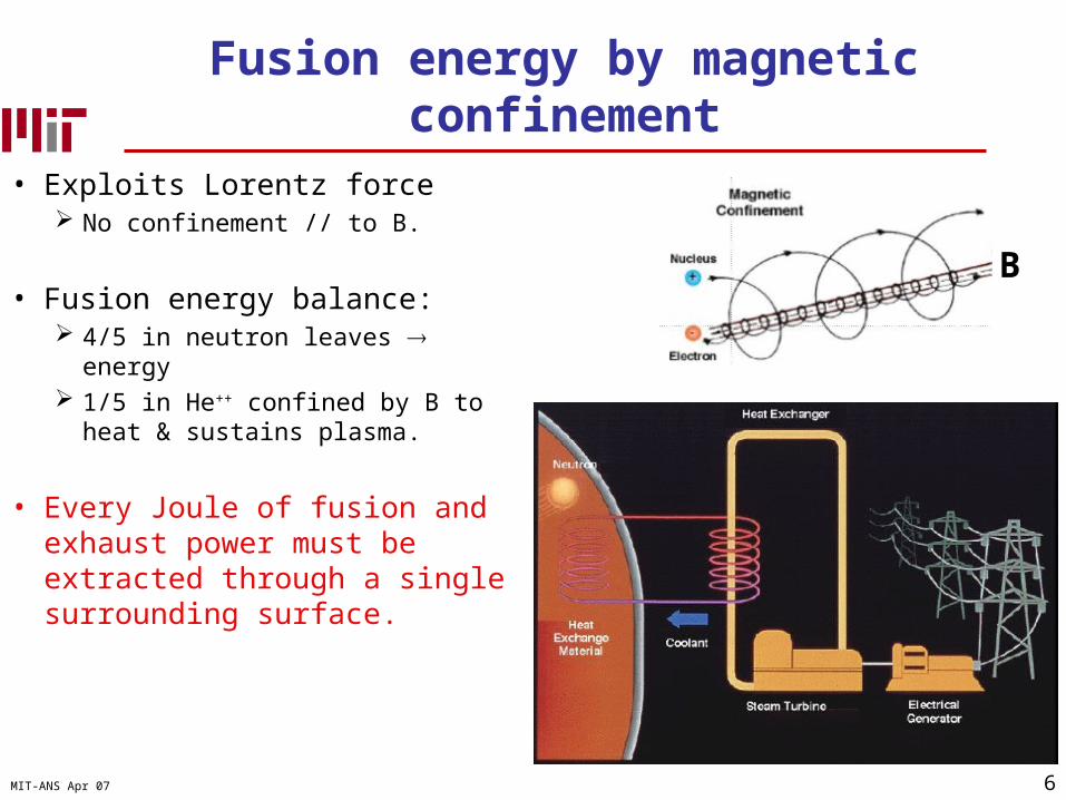
Fusion energy by magnetic confinement
• Exploits Lorentz force No confinement // to B.
• Fusion energy balance: 4/5 in neutron leaves energy 1/5 in He++ confined by B to heat &
sustains plasma.
• Every Joule of fusion and exhaust power must be extracted through a single surrounding surface.
B
7MIT-ANS Apr 07
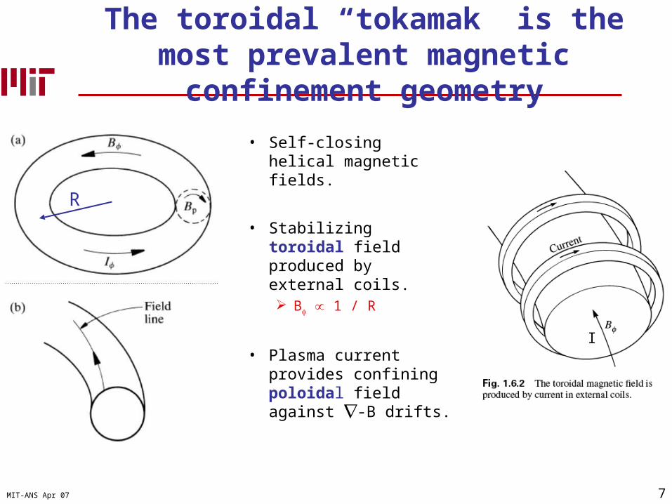
The toroidal “tokamak” is the most prevalent magnetic confinement geometry
• Self-closing helical magnetic fields.
• Stabilizing toroidal field produced by external coils. B 1 / R
• Plasma current provides confining poloidal field against -B drifts.
I
R

8MIT-ANS Apr 07
Plasma pressure, confinement and stability set the requirements for a fusion reactor.
Pfusion n2 T2
PowerBalance
PowerDensity
Confinement
KinkStability€
e ∝ HIp
PH
TripleProduct
Energy Gain
Self-sustaining
Size& Field$$$
Q=5 “burning”

9MIT-ANS Apr 07
Translation of Fusion Strategy
• Build it big, because bigger things hold their heat longer!
• Make the magnetic field as big as possible to hold onto those particles!
• Heat the heck out of it to get 100,000,000 K and light the fire!

10MIT-ANS Apr 07
et voila, ITER
• Mission: “Burning plasma” Q=10
• Reactor level fusion power Pfusion ~ 400 MW for 500 s Heating = 40 MW 20% duty cycle
• Size R~6 m +Field B~6 T = 5 Billion dollars 1000 m3 plasma 1000 m2 plasma-facing wall

11MIT-ANS Apr 07
Like a car, there are several things you have to do to keep the fusion “engine” running.
Power removal Coolant in block, no melting
Fuel control. Gas tank full, no flooding
Helium ash exhaust Tailpipe
Plasma purity No dirt in cylinders
Magnetic topology, plasma physics & the fusion fuel cycle set unique
requirements for wall materials in fusion
Fusion Car

12MIT-ANS Apr 07
Magnetic topology
• Magnetic field line directly terminated on a solid has no confinement due to sink action of wall.
• This separatrix flux surface is the primary interface between thermonuclear plasma and outside world.
• (SOL) Scrape-Off Layer outside separatrix is the “exhaust pipe” of a fusion plasma.
• Divertor targets.

13MIT-ANS Apr 07
Divertor magnetic topologyis presumed for most fusion reactors
• SOL “fed” by cross-field heat and particle losses from “core”
• Advantage Concentrates power and particle
exhaust (q, ) in one location.
• Disadvantages: Concentrates power and particle
exhaust in one location. Wastes magnetic volume.
Core plasma
SOL
q//
/
qtarget, target
surface
Ploss ~ 100-400 MW
B

14MIT-ANS Apr 07
Divertor magnetic topologyis used in ITER (and probably a reactor)
• ITER Magnetic Field-Line Geometry in SOL: Bpoloidal / B ~ 1/10
SOL: L// ~ 100 m
2 R ~ 50 m
ITER Divertor Cross-section
~ 1m

15MIT-ANS Apr 07
Extraordinary plasma heat conduction along B primarily set SOL properties
• // e- Heat conductivity:
€
κ //
κ⊥
∝ ωce τ e−i( )2≅108
€
q// ≈PLoss
2π RL⊥
BT
Bp
~ 2GW
m2
€
L⊥ = L//
κ //
κ⊥
⎛
⎝ ⎜
⎞
⎠ ⎟
−1/ 2
∝100m • 10−4 ≅10−2 m
• ITER energy exhaust: PLoss ~ 150 MW
€
TSOL =7
2
q//
κ o L//
⎛
⎝ ⎜
⎞
⎠ ⎟
2 / 7
≈150eV ~ 1,500,000K
€
q// = κ // ∇T// ≈ κ //
TSOL
L//
€
κSOL ≅ 50, 000W
m ⋅ K~ 100 × κ Cu
€
κ // = κ o T 5 / 2

16MIT-ANS Apr 07
Conforming divertor surface
Constant heat removal at divetor surfaces is daunting: #1 priority in edge “design”
€
qtarget = q//
Bp
B φ
⎛
⎝ ⎜ ⎜
⎞
⎠ ⎟ ⎟divertor
≅ q// 0.02 ≈ 40MW
m2
Field lines
Melts 10 cm of tungsten in ~20 seconds !
Distorted surface “proud” to thefield line receives q// ~ 1 GW/m2
and is immediately melted/ablated.Distorted divertor surface
Field lines€
≈ 50MW
m2
2 R

17MIT-ANS Apr 07
The core fusion plasma has little tolerance to impurities
• Plasma quasi-neutrality sets strict limits for impurities Fuel dilution. Radiation energy losses.
0.0001
0.001
0.01
0.1
0 20 40 60 80
Impurity atomic number
fatal fraction
• Dilute plasma (n~1020 m-3) extinguished by small particulate injection.ITER example: 10 mm3 “drop” of W ~ Ne,plasma
WMo
C

18MIT-ANS Apr 07
Heat exhaust, Tmelt, material stress and heat conductivity set armour thickness
q
dplasmacoolantCoolant
substrate
• Limits material choices to refractory metals (W, Mo) or graphite.
€
dtile = κ plate
(Tmax, surface − Tcoolant )
qtarget
Tungsten CFC carbon
κ (W/m/K) 150 300
Tmelt (K) 3700 3700
dtile ~ 1 cm ~ 2 cm

19MIT-ANS Apr 07
W & C bonding technology capable of exhausting ~ 25 MW/m2
~ 1mITER prototypedivertormodule
castellations

20MIT-ANS Apr 07
Plasma instability leads to large transient heating: Requires high Tmelt materials
• MHD instability = Destruction of nested flux surfaces.
• High Te flux surfaces connect to wall.
• tMHD ~ 0.0001 seconds Edge Localized Mode: ELM Global instability: Disruption
• All energy is “held up” near surface
Kru
ger,
AP
S04
€
δ = D τ MHD ~ 0.1 mm
QuickTime™ and aBMP decompressor
are needed to see this picture.

21MIT-ANS Apr 07
Materials pushed past their thermal limits even in present fusion devices.
• Mo tile “limiter” positioned outside hot core plasma in MIT tokamak (C-Mod)
• Plasma heat exhaust and “non-thermal” electron populations increase past Tmelt ~ 2900 K in < 2 seconds exposure.
• Reactor must run 24/7.

22MIT-ANS Apr 07
Movie Clips of Alcator C-Mod
23MIT-ANS Apr 07
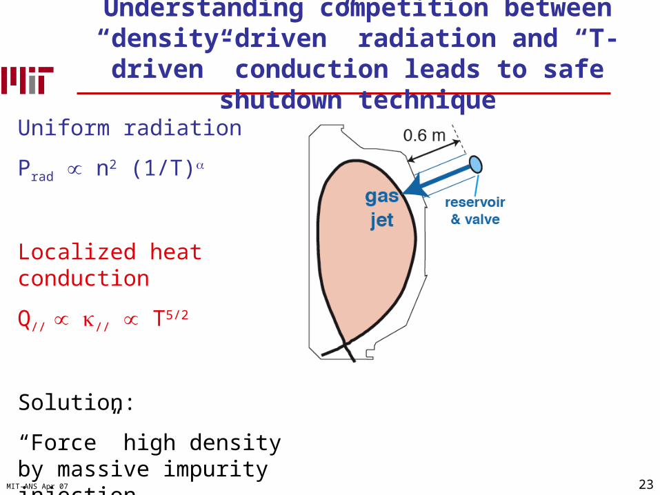
Understanding competition between “density-driven” radiation and “T-driven” conduction
leads to safe shutdown technique
Uniform radiation
Prad n2 (1/T)
Localized heatconduction
Q// κ// T5/2
Solution:
“Force” high density by massive impurity injection

24MIT-ANS Apr 07
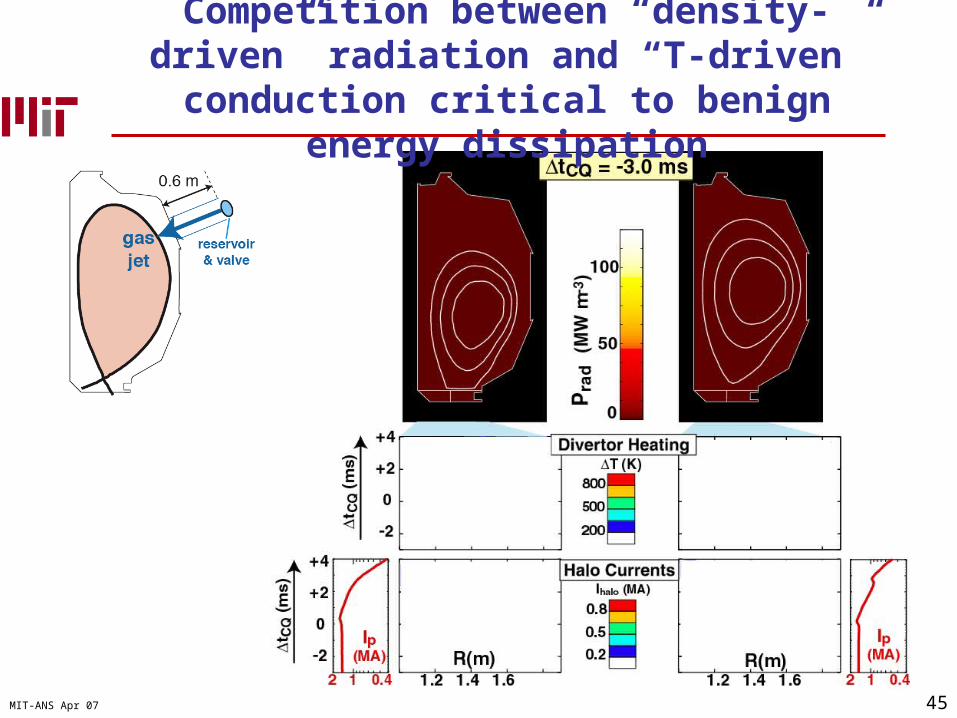
Competition between “density-driven” radiation and “T-driven” conduction critical to
benign energy dissipation
QuickTime™ and aCinepak decompressor
are needed to see this picture.

25MIT-ANS Apr 07
Even ideal radiative energy dissipation can cause material melting in ITER.
Whyte 2004 PSI
Prad ~ 3 TW ~ electricity output of US
Bemelt ~ 100 kG
26MIT-ANS Apr 07
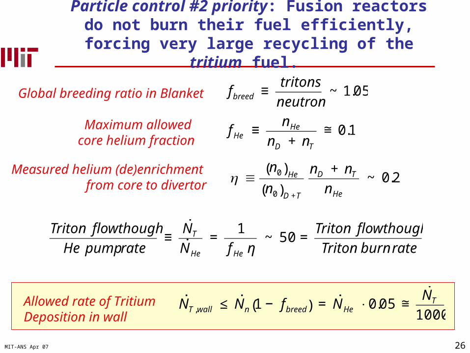
Particle control #2 priority: Fusion reactors do not burn their fuel efficiently, forcing very large recycling of the
tritium fuel.
Global breeding ratio in Blanket
€
fbreed ≡tritons
neutron~ 1.05
Maximum allowed core helium fraction
€
f He ≡nHe
nD + nT
≅ 0.1
Measured helium (de)enrichment from core to divertor
€
η ≡n0( )He
n0( )D +T
nD + nT
nHe
~ 0.2
€
Triton flowthough
He pump rate≡
˙ N T˙ N He
=1
f He η~ 50 =
Triton flowthough
Triton burn rate
Allowed rate of TritiumDeposition in wall
€
˙ N T ,wall ≤ ˙ N n 1 − fbreed( ) = ˙ N He ⋅ 0.05 ≅˙ N T
1000

27MIT-ANS Apr 07
World tritium inventory impacts ability to “start” a fusion energy economy
• A 1000 MWe will burn / produce ~ 0.5 kg ~ 1 pound of Tritium per day.
• The time window for non-T-breeding burners (e.g. ITER, CTF) is short.
• Tritium Breeding Ratio of starting reactors must be > 1 or whole system will
grind to halt from lack of fuel.
J. Schmidt, IEA 2005

28MIT-ANS Apr 07
Developing neutron tolerant materials will probably be last problem solved for fusion
• Uniform material bombardment by 14 MeV neutrons ~ 1m thick blanket to
thermalize, shield neutrons & breed Tritium
• Displacements per atom in wall ~10-20 per year for 1 GW Leads to serious thermal
degradation of materials. Internal p, He production by
nuclear reactions

29MIT-ANS Apr 07
Developing neutron tolerant materials will probably be last problem solved for fusion
• Uniform material bombardment by 14 MeV neutrons ~ 1m thick blanket to thermalize,
shield neutrons & breed Tritium
• Displacements per atom in wall ~10-20 per year for 1 GWth
Leads to serious thermal degradation of materials.
Internal p, He production by nuclear reactions not an issue in fission reactors due E
• Solution will require dedicated experimental & modeling, probably exploiting self-annealing at high material temperatures

30MIT-ANS Apr 07
Neutron irradiation tests of wall materials are needed for fusion reactors
• International Fusion Materials Irradiation Facility will probably be part of broader fusion program.
• Deuteron beam (0.25 MA, ~40 MeV) on flowing lithium target produces fast neutron spectrum But only produces 0.5 L volume that
will receive reactor-like neutron damage (~20 dpa/year)!
IFMIF

31MIT-ANS Apr 07
The material targets must also resist erosion caused by massive energetic particle
throughput in wall
• Vsheath ~ 5 x Te ~ 100-500 eV
€
jion =qtarget
Vsheath
~ 50kA
m2
0.0001
0.001
0.01
0.1
10 100 1000 10000
Incident deuterium ion energy (eV)
Sputter yield
Beryllium
Carbon
Molybdenum
Tungsten
• Plasma ions can rapidly sputter target material away.
€
sputter =jion
k⋅
Y
N target
~ 30nm
s~ 1
m
year
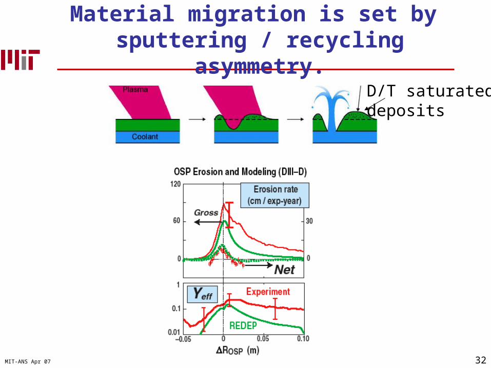
32MIT-ANS Apr 07
Material migration is set by sputtering / recycling asymmetry.
D/T saturateddeposits

33MIT-ANS Apr 07
Divertor “detachment”: Critical to easing power exhaust and sputtering
ne increasing
Alcator C-Mod

34MIT-ANS Apr 07
Detachment solved erosion?
DIII-D:Mapof divertorErosion / deposition
Why
te, I
AE
A 2
000

35MIT-ANS Apr 07
Detachment solved erosion? Yes!Yes, but another problem appeared
DIII-D:Mapof divertorErosion / deposition
Why
te, I
AE
A 2
000Tritium trapped in
plasma deposited films from other wall locations
Rate ~ 1 in 10 fuelled T lost
But requirement:
< 1 in 1000 !
Solution:
> 1000 K walls to deplete H/D/T ?

36MIT-ANS Apr 07
Turbulent cross-field particle transport Erosion sources outside divertor Long-range transport to divertor
QuickTime™ and aYUV420 codec decompressor
are needed to see this picture.
S. Zweben, J. Terry, C-Mod
A. Mclean, et al. DIII-D

37MIT-ANS Apr 07
C-Mod now shows a strong link between ballooning transport, rotation, long-range SOL
transport, T retention and H-mode!
ALCATOR C-Mod, M.I.T.LaBombard, Greenwald APS 04
Ballooningtransport
SOL flow
CoreRotation

38MIT-ANS Apr 07
Besides groundbreaking research on tokamaks like C-Mod, laboratory experiments are coming
online to enhance our understanding of PSI
MAGNUM-PSIHigh power, low Te H plasmas
DIONISOSDynamics of PSI
FOM, Netherlands MIT
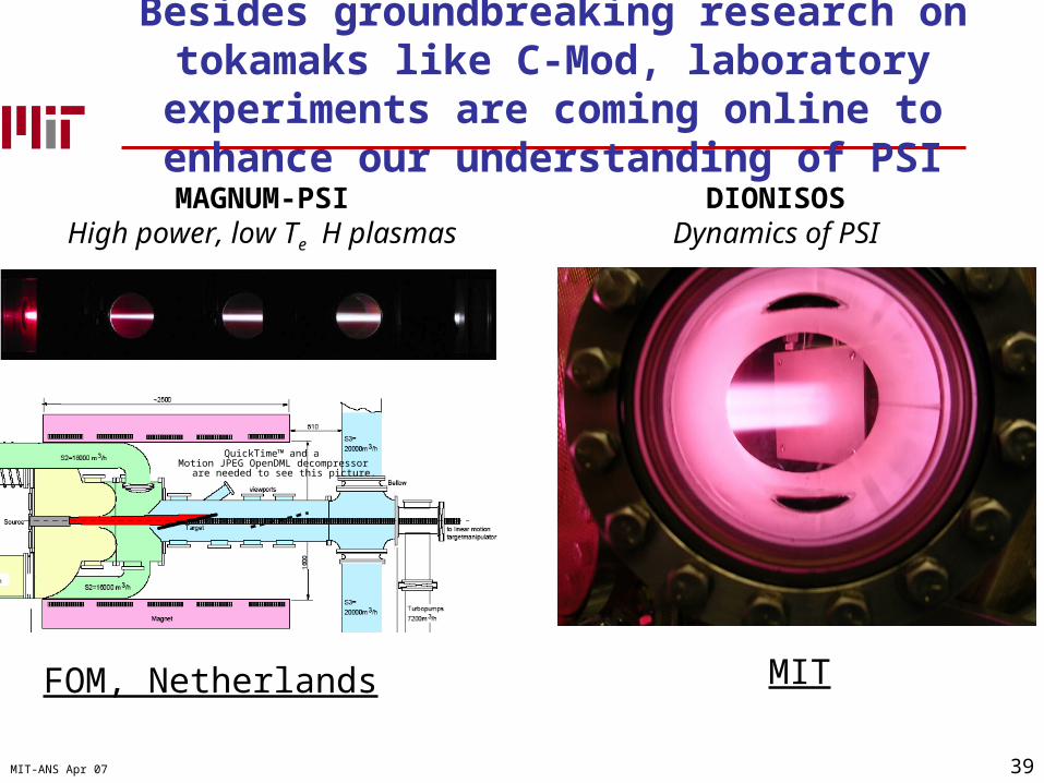
39MIT-ANS Apr 07
Besides groundbreaking research on tokamaks like C-Mod, laboratory experiments are coming
online to enhance our understanding of PSI
MAGNUM-PSIHigh power, low Te H plasmas
DIONISOSDynamics of PSI
FOM, Netherlands MIT
QuickTime™ and aMotion JPEG OpenDML decompressor
are needed to see this picture.
40MIT-ANS Apr 07
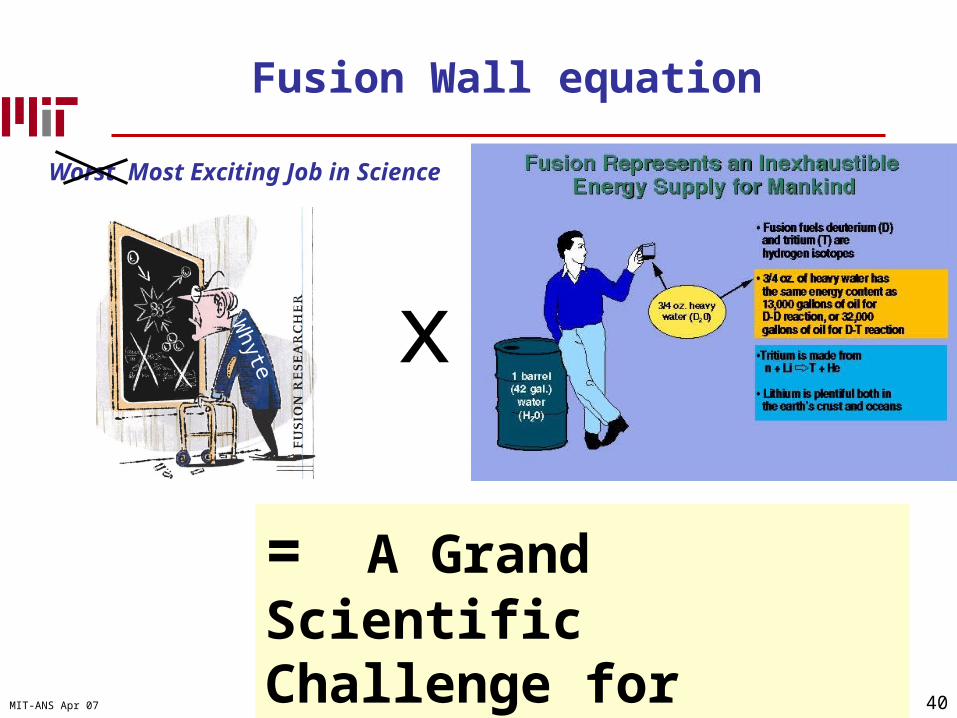
x
= A Grand Scientific Challenge for Ours & Future Generations
Worst Most Exciting Job in Science
Whyte
Fusion Wall equation
41MIT-ANS Apr 07
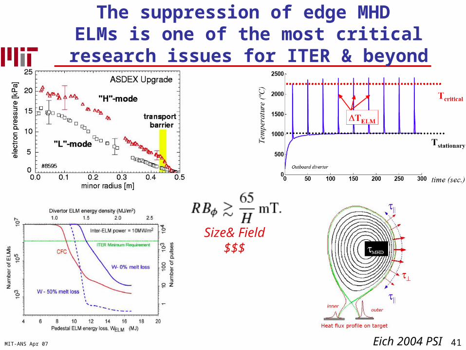
The suppression of edge MHD ELMs is one of the most critical
research issues for ITER & beyond
Eich 2004 PSI
Size& Field$$$

42MIT-ANS Apr 07
Net redeposition or erosion: Deposition rate – erosion rate
Impurity release via sputtering at PFC surface
Impurity ionization & transport near surface
> 90% impurity re-deposited at surface
Local
Net erosion & deposition arises from ~1-10% local flux imbalance
Edge plasma modification by impurity
Core plasma modification from impurities
SOL transport
Release of impurities to SOL
Global
43MIT-ANS Apr 07
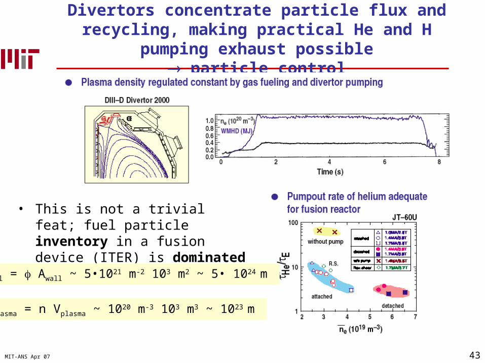
Divertors concentrate particle flux and recycling, making practical He and H pumping exhaust possible
particle control
• This is not a trivial feat; fuel particle inventory in a fusion device (ITER) is dominated by the wall.
Nwall = Awall ~ 5•1021 m-2 103 m2 ~ 5• 1024 m
Nplasma = n Vplasma ~ 1020 m-3 103 m3 ~ 1023 m

44MIT-ANS Apr 07
Parallel heat conduction sustains particle ionization / recycling loop in divertor.
• Consider simple pressure and particle conservation /w Bohm sheath criterion (vtarget = cs)
• Two-point model (Stangeby) Upstream: SOL Target: Divertor
ion,eH
ionization
Core plasma SOL
q////
qtarget, target
surface
Ploss
B
€
Tu ∝ q//2 / 7
€
ntarget ∝ nu3 q//
−8 / 7
€
target ∝ nu2 q//
−3 / 7
€
Ttarget ∝ nu−2 q//
10 / 7
45MIT-ANS Apr 07
Competition between “density-driven” radiation and “T-driven” conduction critical to
benign energy dissipation