1 Metrization and Simulation of Controlled Hybrid...
22
1 Metrization and Simulation of Controlled Hybrid Systems Samuel Burden, Student, IEEE, Humberto Gonzalez, Member, IEEE, Ramanarayan Vasudevan, Member, IEEE, Ruzena Bajcsy, Fellow, IEEE, and S. Shankar Sastry, Fellow, IEEE Abstract The study of controlled hybrid systems requires practical tools for approximation and comparison of system behaviors. Existing approaches to these problems impose undue restrictions on the system’s continuous and discrete dynamics. Metrization and simulation of controlled hybrid systems is considered here in a unified framework by constructing a state space metric. The metric is applied to develop a numerical simulation algorithm that converges uniformly to orbitally stable executions of controlled hybrid systems, up to and including Zeno events. Benchmark examples of novel hybrid phenomena illustrate the utility of the proposed tools. I. I NTRODUCTION For continuous–state dynamical systems and finite–state automata there separately exist rich sets of tools for metrization and simulation. The interaction of discrete transitions with continuous dynamics that is characteristic of controlled hybrid systems requires a new approach. To address this limitation, in this paper we construct a distance metric over the state space of a controlled hybrid system and apply this metric to develop a provably–convergent numerical simulation algorithm. Our framework imposes mild restrictions, enabling formal investigation of a wide range of systems: the dynamics may be nonlinear, the continuous dynamics may be controlled, and multiple discrete transitions may occur simultaneously, so long as executions are orbitally stable. Efforts to topologize and subsequently metrize controlled hybrid systems have been significant but fragmented. Nerode and Kohn [1] consider state–space topologies induced by the finite–state automaton associated with the hybrid system. We propose a metric topology over the state space of controlled hybrid systems, effectively metrizing the hybrifold proposed by Simic et al. [2], as well as the colimit topology constructed by Ames and Sastry [3] over the regularization proposed by Johansson et al. [4]. In contrast, Tavernini [5] directly metrized the space of executions of hybrid systems, and Gokhman [6] later demonstrated the equivalence of the resulting topology with that generated by the Skorokhod trajectory metric (see Chapter 6 in [7]). We highlight the technical and practical limitations imposed by metrizing the trajectory space rather than state space in Section V-C. The notion of regularization or relaxation of a hybrid system should not be confused with the “relax- ation” of hybrid inclusions described by Cai et al. [8]. Since interpreting our controlled hybrid systems as hybrid inclusions yields singleton–valued “flow” and “jump” maps, relaxation in this sense does not yield a distinct hybrid system. Sanfelice and Teel [9] subsequently prove existence of approximating executions for a given “simulation” of a hybrid inclusion. In this paper we consider the opposite problem of proving convergence of approximating simulations for a given execution of a controlled hybrid system. S. Burden was supported in part by an NSF Graduate Research Fellowship. Part of this research was sponsored by the Army Research Laboratory under Cooperative Agreement W911NF-08-2-0004. S. Burden, R. Bajcsy, and S. S. Sastry are with the Department of Electrical Engineering and Computer Sciences, University of California at Berkeley. Email: sburden,bajcsy,[email protected]. H. Gonzalez is with the Department of Electrical & Systems Engineering, Washington University in St. Louis. Email: [email protected]. R. Vasudevan is with the Computer Science and Artificial Intelligence Laboratory, Massachusetts Institute of Technology. Email: [email protected]. arXiv:1302.4402v2 [math.OC] 1 Feb 2014
Transcript of 1 Metrization and Simulation of Controlled Hybrid...

1
Metrization and Simulation of Controlled HybridSystems
Samuel Burden, Student, IEEE, Humberto Gonzalez, Member, IEEE,Ramanarayan Vasudevan, Member, IEEE, Ruzena Bajcsy, Fellow, IEEE, and
S. Shankar Sastry, Fellow, IEEE
Abstract
The study of controlled hybrid systems requires practical tools for approximation and comparison of systembehaviors. Existing approaches to these problems impose undue restrictions on the system’s continuous and discretedynamics. Metrization and simulation of controlled hybrid systems is considered here in a unified framework byconstructing a state space metric. The metric is applied to develop a numerical simulation algorithm that convergesuniformly to orbitally stable executions of controlled hybrid systems, up to and including Zeno events. Benchmarkexamples of novel hybrid phenomena illustrate the utility of the proposed tools.
I. INTRODUCTION
For continuous–state dynamical systems and finite–state automata there separately exist rich sets oftools for metrization and simulation. The interaction of discrete transitions with continuous dynamics thatis characteristic of controlled hybrid systems requires a new approach. To address this limitation, in thispaper we construct a distance metric over the state space of a controlled hybrid system and apply thismetric to develop a provably–convergent numerical simulation algorithm. Our framework imposes mildrestrictions, enabling formal investigation of a wide range of systems: the dynamics may be nonlinear,the continuous dynamics may be controlled, and multiple discrete transitions may occur simultaneously,so long as executions are orbitally stable.
Efforts to topologize and subsequently metrize controlled hybrid systems have been significant butfragmented. Nerode and Kohn [1] consider state–space topologies induced by the finite–state automatonassociated with the hybrid system. We propose a metric topology over the state space of controlledhybrid systems, effectively metrizing the hybrifold proposed by Simic et al. [2], as well as the colimittopology constructed by Ames and Sastry [3] over the regularization proposed by Johansson et al. [4]. Incontrast, Tavernini [5] directly metrized the space of executions of hybrid systems, and Gokhman [6] laterdemonstrated the equivalence of the resulting topology with that generated by the Skorokhod trajectorymetric (see Chapter 6 in [7]). We highlight the technical and practical limitations imposed by metrizingthe trajectory space rather than state space in Section V-C.
The notion of regularization or relaxation of a hybrid system should not be confused with the “relax-ation” of hybrid inclusions described by Cai et al. [8]. Since interpreting our controlled hybrid systems ashybrid inclusions yields singleton–valued “flow” and “jump” maps, relaxation in this sense does not yielda distinct hybrid system. Sanfelice and Teel [9] subsequently prove existence of approximating executionsfor a given “simulation” of a hybrid inclusion. In this paper we consider the opposite problem of provingconvergence of approximating simulations for a given execution of a controlled hybrid system.
S. Burden was supported in part by an NSF Graduate Research Fellowship. Part of this research was sponsored by the Army ResearchLaboratory under Cooperative Agreement W911NF-08-2-0004.
S. Burden, R. Bajcsy, and S. S. Sastry are with the Department of Electrical Engineering and Computer Sciences, University of Californiaat Berkeley. Email: sburden,bajcsy,[email protected].
H. Gonzalez is with the Department of Electrical & Systems Engineering, Washington University in St. Louis. Email:[email protected].
R. Vasudevan is with the Computer Science and Artificial Intelligence Laboratory, Massachusetts Institute of Technology. Email:[email protected].
arX
iv:1
302.
4402
v2 [
mat
h.O
C]
1 F
eb 2
014

2
The literature on numerical simulation of deterministic hybrid systems may be broadly partitioned intotwo groups: practical algorithm development focused on obtaining high–precision estimates of discreteevent times, and theoretical proofs of convergence for simulations of certain classes of hybrid systems.Practical algorithms aim to place time–steps close to discrete event times using root–finding [10], [11], [12].Theoretical proofs of convergence have generally required restrictive assumptions. Esposito et al. [13],for instance, apply feedback linearization to asymptotically guarantee event detection for semi–algebraicguards, while Paoli and Schatzman [14] develop a provably–convergent simulation algorithm for second–order mechanical states undergoing impact specified by a unilateral constraint. The most general con-vergence results relax the requirement that discrete transition times be determined accurately [5], [15],[16], and consequently can accommodate arbitrary nonlinear transition surfaces, Lipschitz continuousvector fields, and continuous discrete transition maps. We extend this approach using our proposed metrictopology to prove convergence of simulations to executions of controlled hybrid systems that satisfy anorbital stability property described in Section IV. Our simulation algorithm may be applied to hybridsystems possessing control inputs and overlapping guards, representing a substantial contribution beyondour previous efforts [16] and those of others [5], [15].
The remainder of our paper is organized as follows. Section II contains definitions of the topological,metric, and dynamical system concepts used throughout the paper. We present our technique for metrizationand relaxation of controlled hybrid systems in Section III and apply these constructions to define a metricfor comparing trajectories in controlled hybrid systems. We then develop our algorithm for numericalsimulation of controlled hybrid system executions in Section IV, where we apply our trajectory metric toprove uniform convergence of simulations to orbitally stable executions. The technique is illustrated inSection V using examples for accuracy, verification, and novel controlled hybrid system behavior.
II. PRELIMINARIES
We begin with the definitions and assumptions used throughout the paper.
A. TopologyThe 2–norm is our finite–dimensional norm of choice unless otherwise specified. Given P , the set of
all finite partitions of R, and n ∈ N, we define the total variation of f ∈ L∞(R,Rn) by:
V(f) = sup
{m−1∑j=0
‖f(tj+1)− f(tj)‖1 | {tk}mk=0 ∈ P, m ∈ N
}, (1)
where L∞(R,Rn) is the set of all almost everywhere bounded functions from R to Rn. The total variationof f is a semi–norm, i.e. it satisfies the Triangle Inequality, but does not separate points. f is of boundedvariation if V(f) < ∞, and we define BV (R,Rn) to be the set of all functions of bounded variationfrom R to Rn.
Given n ∈ N and D ⊂ Rn, ∂D is the boundary of D, and int(D) is the interior of D. Recall thatgiven a collection of sets {Sα}α∈A, where A might be uncountable, the disjoint union of this collection is∐
α∈A Sα =⋃α∈A Sα × {α}, a set that is endowed with the piecewise–defined topology. Throughout the
paper we will abuse notation and say that given α ∈ A and x ∈ Sα, then x ∈∐α∈A Sα, even though weshould write ια(x) ∈∐α∈A Sα, where ια : Sα →
∐α∈A Sα is the canonical identification ια(x) = (x, α).
In this paper we make extensive use of the concept of a quotient topology induced by an equivalencerelation defined on a topological space. We regard a detailed exposition of this important concept asoutside the scope of this paper, and refer the reader to Chapter 3 in [17] or Section 22 in [18] for moredetails. The next definition formalizes equivalence relations in topological spaces induced by functions. Iff : A→ B, V ⊂ A, and V ′ ⊂ B, then we let f(V ) = {f(a) ∈ B | a ∈ V } denote the image of V underf , and f−1(V ′) = {a ∈ A | f(a) ∈ V ′} denote the pre–image of V under f .

3
Definition 1. Let S be a topological space, A,B ⊂ S two subsets, and f : A → B a function. Anf–induced equivalence relation is defined as:
Λf ={
(a, b) ∈ S × S | a ∈ f−1(b), or b ∈ f−1(a), or a = b}. (2)
a, b ∈ S are f–related, denoted by af∼ b, if (a, b) ∈ Λf . Moreover, the equivalence class of x ∈ S is
defined as [x]f ={a ∈ S | a f∼ x
}, and the set of equivalence classes is defined as S
Λf={
[x]f | x ∈ S}
.
We endow the quotient SΛf
with the quotient topology.
Note that Λf is reflexive, symmetric, and transitive, i.e. an equivalence relation. An important application ofthe function–induced quotient is the construction of a single topological space out of several disconnectedsets. Indeed, given a collection of sets {Sα}α∈A, where A is some index set, and a function f : U →∐
α∈A Sα, where U ⊂∐α∈A Sα, then S =∐α∈A Sα
Λfis a topological space.
Next, we present a useful concept from graph theory that simplifies our ensuing analysis.
Definition 2. Let (J ,Γ) be a directed graph, where J is the set of vertices and Γ ⊂ J × J is the setof edges. Then, given j ∈ J , define the neighborhood of j, denoted Nj , by:
Nj = {e ∈ Γ | ∃j′ ∈ J s.t. e = (j, j′)}. (3)
B. Length MetricsEvery metric space has an induced length metric, defined by measuring the length of the shortest curve
between two points. Throughout this paper, we use induced length metrics to metrize the function–inducedquotients of disjoint unions of sets. To formalize this approach, we begin by defining the length of a curvein a metric space; the following definition is equivalent to Definition 2.3.1 in [19].
Definition 3. Let (S, d) be a metric space, I ⊂ [0, 1] be an interval, and γ : I → S be a continuousfunction. Define the length of γ under the metric d by:
Ld(γ) = sup
{k−1∑i=0
d(γ(ti), γ(ti+1)
)| k ∈ N, {ti}ki=0 ⊂ I, t0 < t1 < . . . < tk
}. (4)
We now define a generalization of continuous curves for quotiented disjoint unions.
Definition 4. Let {Sα}α∈A be a collection of sets and f : U →∐α∈A Sα, where U ⊂∐α∈A Sα. γ : [0, 1]→∐
α∈A Sα is f–connected if there exists k ∈ N and {ti}ki=0 ⊂ [0, 1] with 0 = t0 ≤ t1 ≤ . . . ≤ tk = 1 such
that γ|[ti,ti+1) is continuous for each i ∈ {0, 1, . . . , k − 2}, γ|[tk−1,tk] is continuous, and limt↑ti γ(t)f∼ γ(ti)
for each i ∈ {0, 1, . . . , k − 1}. Moreover, in that case {ti}ki=0 is called a partition of γ.
Note that, since each section γ|[ti,ti+1) is continuous, it must necessarily belong to a single set Sα forsome α ∈ A because the disjoint union is endowed with the piecewise–defined topology. In the casewhen A = {α} is a singleton, then every idSα–connected curve is simply a continuous curve over Sα,where idSα denotes the identity function in Sα. Figure 1a shows an example of a connected curve over acollection of two sets.
Using the concept of connected curves, we now define the induced length distance of a collection ofmetric spaces. The induced length distance is a generalization of the induced metric defined in Chapter 2in [19].
Definition 5. Let {(Sα, dα)}α∈A be a collection of metric spaces, and let {Xα}α∈A be a collection of setssuch that Xα ⊂ Sα for each α ∈ A. Furthermore, let f : U → ∐
α∈AXα, where U ⊂ ∐α∈AXα, and let

4
Sα
a+ 1 b b+ 1a0
1Sα
γ(t3)
γ(t1)
γ(t2)
p = γ(0)
q = γ(1)
g
(a) g–connected curve γ with partition {ti}4i=0, where Sα = [a, a+ 1] × [0, 1],Sα = [b, b+ 1]× [0, 1], and g : {a+ 1} × [0, 1]→ {b} × [0, 1] is defined byg(a+ 1, x) = g(b, x).
G(2,3)
f2
R(2,3)
R(2,1)
f1
D1 D2
D3
G(2,1)G(1,2)
G(3,1)
R(1,2)
R(3,1)f3
(b) Illustration of a controlled hybridsystem with three modes.
Fig. 1. An g–connected curve, Fig. 1a, and an example of a controlled hybrid system, Fig. 1b.
X =∐α∈AXα
Λf. di,X : X × X → [0,∞] is the f–induced length distance of X , defined by:
di,X(p, q) = inf
{k−1∑i=0
Ldαi(γ|[ti,ti+1)
)| γ : [0, 1]→
∐α∈A
Xα, γ(0) = p, γ(1) = q,
γ is f–connected, {ti}ki=0is a partition of γ,
{αi}k−1i=0 s.t. γ
([ti, ti+1)
)⊂ Xαi ∀i
}.
(5)
We invoke this definition to metrize both subsets and disjoint unions of metric spaces. It is importantto note that although di,X is non–negative, symmetric, and subadditive, it does not necessarily separatepoints of X (see Section 2.3 in [19]), and hence generally only defines a pseudo–metric. In the specialcase where no function f is supplied, then by convention we let f = idX , the identity function on X .This implies X = X and the induced metric coincides with the given metric. The following Lemma is astraightforward consequence of Proposition 2.3.12 in [19].
Lemma 6. Let (S, d) be a metric space and X ⊂ S. Then di,X is a metric. Moreover, the topology on Xinduced by di,X is equivalent to the topology on X induced by d.
C. Controlled Hybrid SystemsMotivated by the definition of hybrid systems presented in [2], we define the class of hybrid systems
of interest in this paper.
Definition 7. A controlled hybrid system is a tuple H = (J ,Γ,D, U,F ,G,R), where:• J is a finite set indexing the discrete states of H;• Γ ⊂ J × J is the set of edges, forming a directed graph structure over J ;• D = {Dj}j∈J is the set of domains, where each Dj is a subset of Rnj , nj ∈ N;• U ⊂ Rm is the range space of control inputs, m ∈ N;• F = {fj}j∈J is the set of vector fields, where each fj : R×Dj × U → Rnj is a vector field defined
on Dj;• G = {Ge}e∈Γ is the set of guards, where each G(j,j′) ⊂ ∂Dj is a guard in mode j ∈ J that defines
a transition to mode j′ ∈ J ; and,• R = {Re}e∈Γ is the set of reset maps, where each R(j,j′) : G(j,j′) → Dj′ defines the transition from
guard G(j,j′).

5
For convenience, we sometimes refer to controlled hybrid systems as just hybrid systems, and we referto the distinct vertices within the graph structure associated with a controlled hybrid system as modes.Each domain in the definition of a controlled hybrid system is a metric space with the Euclidean distancemetric. A three–mode autonomous hybrid system, which is a particular case of Definition 7 where nonethe vector fields {fj}j∈J depend on the control input, is illustrated in Fig. 1b. Note that we restrict controlinputs to the continuous flow, hence inputs do not have an effect during discrete transitions.
Next, we impose several technical assumptions that support existence and uniqueness of trajectories onhybrid domains.
Assumption 8. Let H be a controlled hybrid system. Then the following statements are true:(1) For each j ∈ J , Dj is a compact nj–dimensional manifold with boundary.(2) U is compact.(3) For each e ∈ Γ, Ge is a closed, embedded, codimension 1, submanifold with boundary.(4) For each e ∈ Γ, Re is continuous.
Assumption 9. For each j ∈ J , fj is Lipschitz continuous. That is, there exists L > 0 such that for eachj ∈ J , t1, t2 ∈ R, x1, x2 ∈ Dj , and u1, u2 ∈ U :∥∥fj(t1, x1, u1)− fj(t2, x2, u2)
∥∥ ≤ L(|t1 − t2|+ ‖x1 − x2‖+ ‖u1 − u2‖
). (6)
Assumption 9 guarantees the existence and uniqueness for ordinary differential equations in individualdomains. In the sequel we will consider control inputs of bounded variation u ∈ BV (R, U). Note thatwithout loss of generality we take 0 as the initial time in the following Lemma; a general initial time canbe accommodated by a straightforward change of variables.
Lemma 10. Let H be a controlled hybrid system. Then for each j ∈ J , each initial condition p ∈ Dj , andeach control u ∈ BV (R, U), there exists an interval I ⊂ R with 0 ∈ I such that the following differentialequation has a unique solution:
x(t) = fj(t, x(t), u(t)
), t ∈ I, x(0) = p. (7)
x is called the integral curve of fj with initial condition p and control u. Moreover, x|I is absolutelycontinuous.
Proof: Let fj : R×Rnj ×U → Rnj be any globally Lipschitz continuous extension to fj (guaranteedto exist by Theorem 1 in [20]). Given any p ∈ Dj ⊂ Rnj and u ∈ BV (R, U), Proposition 5.6.5 in [21]guarantees the existence of an integral curve x : I → Rnj for fj with initial condition x(0) = p. Note thatx is absolutely continuous by Theorem 3.35 in [22]. Let I ⊂ I be the connected component of x−1(Dj)containing 0. Then x = x|I is an absolutely continuous integral curve of fj and x(I) ⊂ Dj . Note that xis unaffected by the choice of extension fj .
The following definition is used to construct executions of a controlled hybrid system.
Definition 11. Let H be a controlled hybrid system, j ∈ J , p ∈ Dj , and u ∈ BV (R, U). x : I → Dj isthe maximal integral curve of fj with initial condition p and control u if, given any other integral curvewith initial condition p and control u, such as x : I → Dj , then I ⊂ I .
Given a maximal integral curve x : I → Dj , a direct consequence1 of Definition 11 and Assumption 8 isthat either sup I = +∞, or sup I = t′ <∞ and x(t′) ∈ ∂Dj . This fact is critical during the definition ofexecutions of a controlled hybrid systems in Section IV.
1This follows from continuity of integral curves and compactness of hybrid domains.

6
D1
∐D2
R
D1 D2
G(1,2) R(1,2)
(G(1,2)
)ΛR−−−−−→
D1 D2
M
Fig. 2. The disjoint union of D1 and D2 (left) and the hybrid quotient space M obtained from the relation ΛR (right).
III. METRIZATION AND RELAXATION OF CONTROLLED HYBRID SYSTEMS
In this section, we metrize a unified family of spaces containing all the domains of a controlled hybridsystem H. The constructed metric space has three appealing properties:
(1) the distance between a point in a guard and its image via its respective reset map is zero;(2) the distance between points in different domains are properly defined and finite; and,(3) the distance between points is based on the Euclidean distance metric from each domain.
A. Hybrid Quotient SpaceUsing Definitions 5 and 7, we construct a metric space where the executions of a controlled hybrid
system reside. The result is a metrization of the hybrifold [2].
Definition 12. Let H be a controlled hybrid system, and let
R :∐e∈Γ
Ge →∐j∈J
Dj (8)
be defined by R(p) = Re(p) for each p ∈ Ge. Then the hybrid quotient space of H is:
M =
∐j∈J Dj
ΛR
. (9)
Fig. 2 illustrates the details about the construction described in Definition 12.The induced length distance on M is in fact a distance metric:
Theorem 13. Let H be a controlled hybrid system, and let di,M be the R–induced length distance of M,where R is defined in (8). Then di,M is a metric on M, and the topology it induces is equivalent to theR–induced quotient topology.
Proof: We provide the main arguments of the proof, omitting the details in the interest of brevity. First,note that each domain is a normal space, i.e. every pair of disjoint closed sets have disjoint neighborhoods.Second, note that each reset map is a closed map, i.e. the image of closed sets under the reset map areclosed. This fact follows by Condition 3 in Assumption 8, since each guard is compact, thus reset mapsare closed by the Closed Map Lemma (Lemma A.19 in [23]).
Let D =∐
j∈J Dj and p, q ∈ D. We aim to show that if p and q yield distinct equivalence classes(i.e. (p, q) /∈ ΛR) then the induced distance between them is strictly positive. Note that the equivalenceclasses [p]R and [q]R are each a finite collection of closed sets. Moreover, since we can construct disjointneighborhoods around each of these closed sets, then we can conclude that there exists δ > 0 such thatdi,M
([p]R, [q]R
)> δ. The proof concludes by following the argument in Exercise 3.1.14 in [19], i.e.
since each connected component in D is bounded, then M is also bounded (in the quotient topology).

7
Then, using a simple extension of Theorem 5.8 in [17]2, we get that the identity map from M to thespace constructed by taking the quotient of all the points in D such that di,M has zero distance is ahomeomorphism, thus they have the same topology.It is crucial to note that all R–connected curves are continuous in the topology induced by the metric di,Mon the hybrid quotient space M. This implies in particular that executions of controlled hybrid systems(to be defined in Section IV) are continuous in M since the endpoint of the segment of an executionthat lies in a guard Ge will be R–related to the startpoint of the subsequent segment of the execution;alternately, this follows from Theorem 3.12(b) in [2] sinceM is equivalent to the “hybrifold” constructionin that paper. This important property is foundational to the convergence results for sequences of (relaxed)executions and their simulations derived in Section IV. For further details, we refer the interested readerto Examples 3.2 and 3.3 in [2] where continuity is clearly discussed for simple examples.
B. Relaxation of a Controlled Hybrid SystemTo construct a numerical simulation scheme which does not require the exact computation of the time
instant when an execution intersects a guard, we require a method capable of introducing some slacknesswithin the computation. This is accomplished by relaxing each domain along its guard and then relaxingeach vector field and reset map accordingly in order to define a relaxation of a controlled hybrid system.
To formalize this approach, we begin by defining the relaxation of each domain of a controlled hybridsystem, which is accomplished by first attaching an ε–sized strip to each guard.
Definition 14. Let H be a controlled hybrid system. For each e ∈ Γ, let Sεe = Ge × [0, ε] be the stripassociated to guard Ge. For each j ∈ J , let
χj :∐e∈Nj
Ge →∐e∈Nj
Sεe , (10)
be the canonical identification of each point in a guard with its corresponding strip defined for eachp ∈ Ge as χj(p) = (p, 0) ∈ Sεe . Then, the relaxation of Dj is defined by:
Dεj =
Dj
∐(∐e∈Nj S
εe
)Λχj
. (11)
By Condition 3 in Assumption 8, each point on a strip Sεe of Dj is defined using nj coordinates(ζ1, . . . , ζnj−1, τ), shortened (ζ, τ), where τ is called the transverse coordinate and is the distance alongthe interval [0, ε]. An illustration of Definition 14 together with the coordinates on each strip is shown inFig. 3a.
We endow each Sεe with a distance metric in order to define an induced length metric on a relaxeddomain Dε
j .
Definition 15. Let j ∈ J and e ∈ Nj . Endow Dj with di,Dj as its metric, and dSεe : Sεe × Sεe → [0,∞) asthe metric on Sεe , defined for each ζ, ζ ′ ∈ Ge and τ, τ ′ ∈ [0, ε] by:
dSεe((ζ, τ), (ζ ′, τ ′)
)= di,Ge(ζ, ζ
′) + |τ − τ ′|. (12)
We now define a length metric on relaxed domains using Definitions 4 and 5.
Theorem 16. Let j ∈ J , and let di,Dεj be the χj–induced length distance on Dεj , where χj is as defined
in (10). Then di,Dεj is a metric on Dεj , and the topology it induces is equivalent to the χj–induced quotient
topology.
2The extension aims to allow the domain of the map to be bounded instead of compact. The new proof follows step–by–step the argumentin [17].

8
ζ
τ
Sε(1,3)
D1
∐Sε(1,2)
∐Sε(1,3)
τ
ζ
ε
Sε(1,2)G(1,2)
G(1,3)
ι1
ι1
D1
Λχ1−−−→Sε(1,3)
G(1,2)
G(1,3)
D1
Sε(1,2)
ε
Dε1
(a) Disjoint union of D1 and the strips in its neighborhood, {Sεe}e∈N1(left), and the
relaxed domain Dε1 obtained from the relation Λχ1 (right).
f(1,3)Sε(1,3)
Sε(1,2)
ε
D1
f1f(1,2)
τζ
(b) Relaxed vector field fε1 on Dε1.
Fig. 3. An illustration of the construction of a relaxed domain, Fig. 3a, and the relaxed vector field defined on it, Fig. 3b.
Proof: Since di,Dεj is non–negative, symmetric, and subadditive, it remains to show that it separatespoints. Let p, q ∈ Dε
j . First, we want to show that [p]χj = [q]χj whenever di,Dεj (p, q) = 0. Note that foreach e ∈ Nj and each pair p, q ∈ Ge, and by the Definition 5 and 15, dSεe ((p, 0), (q, 0)) ≥ di,Dj(p, q),hence no connected curve that “jumps” to a strip can be shorter than a curve that stays in Dj . This factimmediately shows that for p, q ∈ Dj , di,Dεj (p, q) = 0 implies that [p]χj = [q]χj . The case when one of thepoints is in Ge×(0, ε] ⊂ Sεe follows easily by noting that those points can be separated by a suitably–sizeddSεe–ball. The proof concludes by following the argument in Exercise 3.1.14 in [19], as we did in theproof of Theorem 13.Refer to di,Dεj as the relaxed domain metric. Note that Theorem 16 can be proved using the same argumentas in the proof of Theorem 13, but we prove Theorem 16 to emphasize the utility of the inequality relatingthe induced metric on a domain and the metric on each strip.
Next, we define a vector field over each relaxed domain.
Definition 17. Let j ∈ J . For each e ∈ Nj , let the vector field on the strip Sεe , denoted fe, be the unit vectorpointing outward along the transverse coordinate. In coordinates, fe
(t, (ζ, τ), u
)=(0, . . . , 0︸ ︷︷ ︸ζ coords.
, 1)T . Then,
the relaxation of fj is:
f εj (t, x, u) =
{fj(t, x, u) if x ∈ Dj,
fe(t, x, u) if x ∈ Ge × (0, ε] ⊂ Sεe , for some e ∈ Nj.(13)
Note that the relaxation of the vector field is generally not continuous along each Ge, for e ∈ Nj . Aswe show in the algorithm in Fig. 7, this discontinuous vector field does not lead to sliding modes on theguards [24], [25], since the vector field on the strips always points away from the guard. An illustrationof the relaxed vector field f εj on Dε
j is shown in Fig. 3b.The definitions of relaxed domains and relaxed vector fields allow us to construct a relaxation of the
controlled hybrid systems as follows:
Definition 18. Let H be a controlled hybrid system. We say that the relaxation of H is a tuple Hε =(J ,Γ,Dε, U,F ε,Gε,Rε), where:• Dε =
{Dεj
}j∈J is the set of relaxations of the domains in D, and each Dε
j is endowed with itsinduced length distance metric di,Dεj ;
• F ε ={f εj}j∈J is the set of relaxations of the vector fields in F;
• Gε ={Gεe
}e∈Γ
is the set of relaxations of the guards in G, where Gεe = Ge × {ε} ⊂ Sεe for each
e ∈ Γ; and,

9
ε
Gε(1,2)
Dε1
∐Dε
2 Dε2Dε
1
Rε(1,2)
(Gε(1,2)
)Rε Λ
Rε−−−−−−→
ε
Dε2
Mε
Dε1
Fig. 4. The disjoint union of Dε1 and Dε
2 (left), and the relaxed hybrid quotient space Mε obtained from the relation ΛRε (right).
• Rε ={Rεe
}e∈Γ
is the set of relaxations of the reset maps in R, where Rεe : Gε
e → Dj′ for eache = (j, j′) ∈ Γ and Rε
e(ζ, ε) = Re(ζ) for each ζ ∈ Gεe.
C. Relaxed Hybrid Quotient SpaceAnalogous to the construction of the metric quotient spaceM, using Definitions 5 and 18 we construct
a unified metric space where executions of relaxations of controlled hybrid systems reside. The result is ametrization of the hybrid colimit [3] rather than a metrization of the hybrifold as in the previous section.
Definition 19. Let Hε be the relaxation of the controlled hybrid system H. Also, let
Rε :∐e∈Γ
Gεe →
∐j∈J
Dεj (14)
be defined by Rε(p) = Rεe(p) for each p ∈ Gε
e. Then the relaxed hybrid quotient space of Hε is:
Mε =
∐j∈J D
εj
ΛRε. (15)
The construction in Definition 19 is illustrated in Fig. 4.We now show that the induced length distance on Mε is indeed a metric. We omit this proof since it
is identical to the proof of Theorem 13.
Theorem 20. Let H be a controlled hybrid system, let Hε be its relaxation, and let di,Mε be the Rε–induced length distance of Mε, where Rε is defined in (14). Then di,Mε is a metric on Mε, and thetopology it induces is equivalent to the Rε–induced quotient topology.
All Rε–connected curves are continuous under the metric topology induced by di,Mε which is importantwhen we study executions of hybrid systems in Section IV.
As expected, the metric on Mε converges pointwise to the metric on M.
Theorem 21. Let H be a controlled hybrid system, and let Hε be its relaxation. Then for all p, q ∈ M,di,Mε(p, q)→ di,M(p, q) as ε→ 0.
Proof: Abusing notation, let L(γ) denote the length of any connected curve γ, defined as the sum ofthe lengths of each of its continuous sections under the appropriate metric. First, note that di,M(p, q) ≤di,Mε(p, q). This inequality follows since, as we argued in the proof of Theorem 16, given an edge(j, j′) ∈ Γ, dSε
(j,j′)((p′, 0), (q′, 0)) ≥ di,Dj(p
′, q′) for any pair of points p′, q′ ∈ G(j,j′). Thus, adding thestrips {Se}e∈γ in Mε only make the length of a connected curve longer.
Now let D =∐
j∈J Dj and Dε =∐
j∈J Dεj . Given δ > 0, there exists γ : [0, 1]→ D, an R–connected
curve with partition {ti}ki=0, such that γ(0) = p, γ(1) = q, and di,M(p, q) ≤ L(γ) ≤ di,M(p, q) + δ.Moreover, without loss of generality let γε : [0, 1]→ Dε be an Rε–connected curve that agrees with γ on

10
Require: t = 0, j ∈ J , p ∈ Dj , and u ∈ BV (R, U).1: Set x(0) = p.2: loop3: Let γ : I → Dj be the maximal integral curve of fj with control u such that γ(t) = x(t).4: Let t′ = sup I and x(s) = γ(s) for each s ∈ [t, t′). . Note if t′ <∞, then γ(t′) ∈ ∂Dj .5: if t′ =∞, or @e ∈ Nj such that γ(t′) ∈ Ge then6: Stop.7: end if8: Let (j, j′) ∈ Nj be such that γ(t′) ∈ G(j,j′).
9: Set x(t′) = R(j,j′)
(γ(t′)
), t = t′, and j = j′. . Note γ(t′)
R∼ x(t′).10: end loop
Fig. 5. Algorithm to construct an execution of a controlled hybrid system H.
D, i.e. each section of γε on D is identical, up to time scaling, to a section of γ Thus γε has at most kε–length extra sections, and L(γ) ≤ L(γε) ≤ L(γ) +kε. Thus, di,Mε(p, q) ≤ L(γε) ≤ di,M(p, q) +kε+ δ.The result follows after noting this inequality is valid for all δ > 0, thus di,Mε(p, q) ≤ di,M(p, q).Note that Theorem 21 does not imply that the topology of Mε converges to the topology of M. On thecontrary, Mε is homotopically equivalent to the graph (J ,Γ) for each ε > 0 [3], whereas the topologyof M may be different [2].
We conclude this section by introducing metrics between curves on Mε.
Definition 22. Let I ⊂ [0,∞) a bounded interval. Given any two curves γ, γ′ : I →Mε, we define:
ρεI(γ, γ′
)= sup
{di,Mε
(γ(t), γ′(t)
)| t ∈ I
}. (16)
Our choice of the supremum among point–wise distances in Definition 22 is inspired by the sup–normfor continuous real–valued functions.
IV. RELAXED EXECUTIONS AND DISCRETE APPROXIMATIONS
This section contains our main result: discrete approximations of trajectories of controlled hybridsystems, constructed using any variable step size numerical integration algorithm, converge uniformlyto the actual trajectories. This section is divided into three parts. First, we define a pair of algorithms thatconstruct executions of controlled hybrid systems and their relaxations, respectively. Next, we developa discrete approximation scheme for executions of relaxations of controlled hybrid systems. Finally, weprove that these discrete approximations converge to the executions of the original, non–relaxed, controlledhybrid system using the metric topologies developed in Section III.
A. Execution of a Hybrid SystemWe begin by defining an execution of a controlled hybrid system. This definition agrees with the
traditional intuition about executions of controlled hybrid systems which describes an execution as evolvingas a standard control system until a guard is reached, at which point a discrete transition occurs to a newdomain using a reset map. We provide an explicit definition to clarify technical details required in theproofs below. Given a controlled hybrid system, H, as in Definition 7, the algorithm in Fig. 5 definesan execution of H via construction. A resulting execution, denoted x, is an R–connected curve fromsome interval I ⊂ [0,∞) to
∐j∈J Dj . Thus, abusing notation, we regard x as a continuous curve on M.
Abusing notation again, we regard x as a piece–wise continuous curve on Mε for each ε > 0. Fig. 6ashows an execution undergoing a discrete transition.
Note that executions constructed using the algorithm in Fig. 5 are not necessarily unique. Indeed,Definition 11 implies that once a discrete transition has been performed, the execution is unique until a

11
G(1,2)
D1
R(1,2)
(G(1,2)
)
x(0)
D2
x(t′)
M
(a) Discrete transition of an executionx.
D1
p′
D2
M
x(0)
G(1,2) G(2,1)
(b) Zeno execution x accumulatingat p′.
R(1,2)
(G(1,2)
)G(1,2)
D1 D2M
p′
(c) Non–orbitally stable execution withrespect to the initial condition p′.
Fig. 6. Examples of different executions for a two–mode hybrid system.
new transition is made; however, the choice in Step 8 is not necessarily unique if the maximal integralcurve passes through the intersection of multiple guards. It is not hard to prove that a sufficient conditionfor uniqueness of executions is that all the guards are disjoint, even though, as we show in Section V-C,uniqueness of the executions can be obtained for some cases where guards do intersect.
With the definition of execution of a controlled hybrid system, we can define a class of executionsunique to controlled hybrid systems.
Definition 23. An execution is Zeno when it undergoes an infinite number of discrete transitions in afinite amount of time. Hence, there exists T > 0, called the Zeno Time, such that the execution is onlydefined on I = [0, T ).
Zeno executions are hard to simulate since they apparently require an infinite number of reset mapevaluations, an impossible task to implement on a digital computer. A consequence of the algorithm inFig. 5 is that if x : I →M is an execution such that T = sup I <∞, then either
(1) x has a finite number of discrete transitions on I = [0, T ], and x(T ) ∈ ∂Dj for some j ∈ J , or(2) x is a Zeno execution and I = [0, T ).We now introduce a property of Zeno executions of particular interest in this paper:
Definition 24. Let H be a controlled hybrid system, p ∈ M, u ∈ BV (R, U), and x : [0, T ) → M bea Zeno execution with initial condition p, control u, and Zeno Time T . x accumulates at p′ ∈ M iflimt→T di,M
(x(t), p′
)= 0.
Examples of Zeno executions that do not accumulate can be found in [26]. Fig. 6b shows a Zeno executionthat accumulates at p′. Note that for p′ to be a Zeno accumulation point, it must belong to a guard of acontrolled hybrid system.
Since M is a metric space, we can introduce the concept of continuity of a hybrid execution withrespect to its initial condition and control input in a straightforward way. Employing this definition, wecan define the class of executions that are numerically approximable:
Definition 25. Let H be a controlled hybrid system, and assume that all the executions of H are unique.Denote by x(p,u) : I(p,u) → M the hybrid execution of H with initial condition p ∈ M and controlu ∈ BV (R, U). Given T > 0, we say that the map (p, u) 7→ x(p,u) is orbitally stable in [0, T ] at(p′, u′) ∈M×BV (R, U) if there exists a neighborhood of (p′, u′), say N(p′,u′) ⊂M×BV (R, U), suchthat the following conditions are satisfied:
(1) [0, T ] ⊂ I(p,u) for each (p, u) ∈ N(p′,u′).(2) The map (p, u) 7→ x(p,u)(t) is continuous at (p′, u′) for each t ∈ [0, T ].
As observed in Section III.B in [27], executions that are not orbitally stable are difficult to approximate

12
Require: t = 0, j ∈ J , p ∈ Dj , and u ∈ BV (R, U).1: Set xε(0) = p.2: loop3: Let γ : I → Dj , the maximal integral curve of fj with control u such that γ(t) = xε(t).4: Let t′ = sup I and xε(s) = γ(s) for each s ∈ [t, t′). . Note if t′ <∞, then γ(t′) ∈ ∂Dj .5: if t′ =∞, or @e ∈ Nj such that γ(t′) ∈ Ge then6: Stop.7: end if8: Let (j, j′) ∈ Nj such that γ(t′) ∈ G(j,j′), thus
(γ(t′), 0
)∈ Sε(j,j′).
9: Set xε(t′+τ) =(γ(t′), τ
)for each τ ∈ [0, ε).
10: Set xε(t′+ε) = Rε(j,j′)
(γ(t′), ε
), t = t′+ε, and j = j′. . Note
(γ(t′), ε
) Rε∼xε(t′+ε).11: end loop
Fig. 7. Algorithm to construct a relaxed execution of a relaxation of a controlled hybrid system, Hε.
with a general algorithm. Figure 6c shows a non–orbitally stable execution that intersects the guardtangentially, and note that executions initialized arbitrarily close to p′ ∈ D1 undergo different sequencesof transitions. Unfortunately, there is presently no general test (analytical or numerical) that ensures agiven execution is orbitally stable. Theorem III.2 in [27] provides one set of sufficient conditions ensuringorbital stability.
B. Relaxed Execution of a Hybrid SystemNext, we define the concept of relaxed execution for a relaxation of a controlled hybrid system. The
main idea is that, once a relaxed execution reaches a guard, we continue integrating over the strip withthe relaxed vector field, fe, as in Definition 17. Given the controlled hybrid system, H, its relaxation, Hε,for some ε > 0, the algorithm in Fig. 7 defines a relaxed execution of Hε via construction. The resultingrelaxed execution, denoted xε, is a continuous function defined from an interval I ⊂ [0,∞) to Mε. Notethat this algorithm is only defined for initial conditions belonging to Dj for some j ∈ J since the stripsare artificial objects that do not appear in H. The generalization to all initial conditions is straighforward;we omit it to simplify the presentation.
Step 9 of the algorithm in Fig. 7 relaxes each instantaneous discrete transition by integrating over thevector field on a strip, hence forming a continuous curve on Mε. Also note that our definition for therelaxed execution over each strip Sεe , also in Step 9, is exactly equal to the maximal integral curve of fe.Fig. 8a shows an example of a relaxed mode transition produced the algorithm in Fig. 7. Given a hybridsystem H and its relaxation Hε, the relaxed execution of Hε produced by the algorithm in Fig. 7 is adelayed version of the execution of H produced by the algorithm in Fig. 5, since the relaxed version hasto expend ε time units during each discrete transition. In that sense, our definition of relaxed executionis equivalent to an execution of a regularized hybrid systems [4].
Note that if a relaxed execution is unique for a given initial condition and input, then the correspondinghybrid execution is also unique, but not vice versa. Indeed, consider the case of a hybrid executionperforming a single discrete transition at a point, say p, where two guards intersect, i.e. p ∈ Ge andp ∈ Ge′ , such that Re(p) = Re′(p). In this case the hybrid execution is unique, but its relaxed counterparteither evolves via Se or Se′ , hence obtaining 2 different executions. Nevertheless, both relaxed executionsreach the same point after evolving over the strip.
Next, we state our first convergence theorem.
Theorem 26. Let H be a controlled hybrid system and Hε be its relaxation. Let p ∈M, u ∈ BV (R, U),x : I → Mε be an execution of H with initial condition p and control u, and let xε : Iε → Mε be acorresponding relaxed execution of x. Assume that the following conditions are satisfied:

13
xε(t′) xε(t′ + ε)
Rε(1,2)
(Gε(1,2)
)Dε2
Mε
G(1,2)
Dε1
εxε(0)
(a) Relaxed mode transition of a relaxed execution xε
in a two–mode relaxed hybrid dynamical system.
Dε1
zε,h(tk)
τzε,h(tk+2)
ε
Rε(1,2)
(Gε(1,2)
)Dε2
Mε
G(1,2)
zε,h(0)
(b) Discrete approximation zε,h of a relaxed execu-tion in a two-mode hybrid dynamical system.
Fig. 8. A relaxed execution (left) and its discrete approximation (right).
(1) x is orbitally stable with initial condition p and control u;(2) x has a finite number of discrete transitions or is a Zeno execution that accumulates; and(3) there exists T > 0 such that for each ε small enough, [0, T ] ⊂ I ∩ Iε if x has a finite number of
discrete transitions, and [0, T ) ⊂ I ∩ Iε if x is Zeno.Then, limε→0 ρ
ε[0,T ]
(x, xε
)= 0.
Proof: We provide the main arguments of the proof, omitting some details in the interest of brevity.First, given j ∈ J and [τ, τ ′) ⊂ [0, T ] such that x(t) ∈ Dj for each t ∈ [τ, τ ′), then, since x|[τ,τ ′) isabsolutely continuous, for each t, t′ ∈ [τ, τ ′),
di,Mε
(x(t), x(t′)
)≤ Ldi,Dj
(x|[t,t′)
)=
∫ t′
t
∥∥fj(s, x(s), u(s))∥∥ ds ≤ K(t′ − t), (17)
where K = sup{∥∥f εj (t, x, u)∥∥ | j ∈ J , t ∈ [0, T ], x ∈Mε, u ∈ U
}<∞.
Second, let k ∈ N and {λi}ki=0 ⊂ [0, 1] be a sequence such that 0 = λ0 ≤ λ1 ≤ . . . ≤ λk = 1. Givenε > 0, let γt : [0, 1] → Mε be defined by γt(λ) = xλε(t). Thus, by Theorem 21 and the algorithm inFigure 7, γt(0) = x0(t) = x(t) and γt(1) = xε(t). Assume that xε(t) ∈ Dj for each t ∈ [τ + ε, τ ′ + ε),where [τ, τ ′) is as defined above. Using Picard’s Lemma (Lemma 5.6.3 in [21]), for each t ∈ [τ + ε, τ ′),
‖xε(t+ ε)− x(t)‖ ≤ eL(t−τ)
(‖xε(τ + ε)− x(τ)‖+
+
∫ t
τ
∥∥fj(s, x(s), u(s))− fj
(s+ ε, x(s), u(s+ ε)
)∥∥ ds
)≤ eL(t−τ)
(‖xε(τ + ε)− x(τ)‖+ L
∫ t
τ
ε+ ‖u(s)− u(s+ ε)‖ ds
)≤ eL(t−τ)
(‖xε(τ + ε)− x(τ)‖+
(L+ V(u)
)(t− τ)ε
),
(18)
where we have used a standard property of the functions of bounded variation (Exercise 5.1 in [28]). Thus,if we assume that ‖xε(τ + ε)− x(τ)‖ = O(ε), i.e. that there exists C > 0 such that ‖xε(τ + ε)− x(τ)‖ ≤Cε, then ‖xε(t+ ε)− x(t)‖ = O(ε) for each t ∈ [τ + ε, τ ′). Using the same argument as above∥∥xλi+1ε(t+ ε)− xλiε(t)
∥∥ = O((λi+1 − λi)ε), which implies that γt is continuous for each t ∈ [τ + ε, τ ′),and that L(γt) = O(ε), hence di,Dj
(xε(t+ ε), x(t)
)= O(ε).
Assuming now that x performs 2 discrete transitions at times τ, τ ′ ∈ [0, T ], such that τ + ε < τ ′,transitioning from mode j to j′, and the from mode j′ to j′′. Note that, by definition, x|[0,τ) = xε|[0,τ).Moreover, since x is orbitally stable, we know that xε performs the same 2 discrete transitions for ε smallenough. Let τ ε + ε ∈ [0, T ] be such that xε(τ ε + ε) ∈ G(j′,j′′). Note that |τ ε − τ ′| = O(ε) since xε → x

14
uniformly and x is Lipschitz continuous (both propositions shown above). Assume that τ ′ ≤ τ ε + ε andconsider the following upper bounds:
(1) If t ∈ [τ, τ + ε), then x(t) ∈ Dj′ and xε(t) ∈ Sε(j,j′), thus:
di,Mε
(x(t), xε(t)
)≤ di,Dj′
(x(t), x(τ)
)+ dSε
(j,j′)
(x(τ), xε(t)
)= O(ε). (19)
(2) If t ∈ [τ + ε, τ ′), then x(t), xε(t) ∈ Dj′ , thus, using the bound obtained above:
di,Mε
(x(t), xε(t)
)≤ di,Dj′
(x(t), x(t− ε)
)+ di,Dj′
(x(t− ε), xε(t)
)= O(ε). (20)
(3) If t ∈ [τ ′, τ ε + ε), then x(t) ∈ Dj′′ and xε ∈ Dj′ , thus, denoting limt↑τ ′ x(t) = x(τ ′−):
di,Mε
(x(t), xε(t)
)≤ di,Dj′′
(x(t), x(τ ′)
)+ dSε
(j′,j′′)
(x(τ ′), x(τ ′−)
)+
+ di,Dj′(x(τ ′−), xε(τ ε + ε)
)+ di,Dj′
(xε(τ ε + ε), xε(t)
)≤ O(ε).
(21)
(4) If t ∈ [τ ε + ε, τ ε + 2ε), then x(t) ∈ Dj′′ and xε ∈ Sε(j′.j′′), thus:
di,Mε
(x(t), xε(t)
)≤ di,Dj′′
(x(t), x(τ ′)
)+ dSε
(j′,j′′)
(x(τ ′), xε(t)
)≤ O(ε). (22)
(5) If t ∈ [τ ε + 2ε, T ], then x(t), xε(t) ∈ Dj′′ , thus we get the same bound as in case 2.Therefore, ρε[0,T ](x, x
ε) = O(ε) as desired. Note that the general case, with an arbitrary number of discretetransitions and where the discrete transitions of xε occur before the discrete transitions of x, follows byusing the a similar argument as above by properly considering the time intervals and then applying theupper bounds inductively.
Next, let us consider the case when x is a Zeno execution that accumulates on p′. Let δ > 0, thenx|[0,T−δ] has a finite number of discrete transitions, and as shown above, di,Mε
(x(T−δ), xε(T−δ)
)= O(ε).
Moreover, di,Mε
(x(T − δ), x(t)
)= O(δ) and di,Mε
(xε(T − δ), xε(t)
)= O(δ) for each t ∈ [T − δ, T ). The
conclusion follows by noting that these bounds are valid for each δ > 0.
C. Discrete ApproximationsFinally, we are able to define the discrete approximation of a relaxed execution, which is constructed
as an extension of any existing ODE numerical integration algorithm. Given a controlled hybrid systemH, Ahj : R × Rnj × U → Rnj , where h > 0 and j ∈ J , is a numerical integrator of order ω, if givenp ∈ Dj , u ∈ BV (R, U), x the maximal integral curve of fj with initial condition p and control u,N =
⌊Th
⌋, and a sequence {zk}Nk=0 with z0 = p and zk+1 = Ahj
(kh, zk, u(kh)
), then sup
{‖x(kh)− zk‖ |
k ∈ {0, . . . , N}}
= O(hω). This definition of numerical integrator is compatible with commonly usedalgorithms, including Forward and Backward Euler algorithms and the family of Runge–Kutta algorithms(Chapter 7 in [29]). The algorithm in Fig. 9 defines a discrete approximation of a relaxed execution ofHε. The resulting discrete approximation, for a step size h > 0, denoted by zε,h, is a function from aclosed interval I ⊂ [0,∞) to Mε.
We now make several remarks about the algorithm in Fig. 9. First, the condition in Step 4 can only besatisfied, i.e. the Algorithm only stops, if zε,h(tk) ∈ ∂Dj and fj
(tk, z
ε,h(tk), u(tk))
is outward–pointing,since otherwise a smaller step–size would produce a valid point. Second, the function zε,h is continuouson Mε. Third, and most importantly, similar to the algorithm in Fig. 7, the curve assigned to zε,h inStep 11 is exactly the maximal integral curve of fe while on the strip. By relaxing the guards using strips,and then endowing the strips with a trivial vector field, we avoid having to find the exact point where thetrajectory intersects a guard. Our relaxation does introduce an error in the approximation, but as we showin Theorem 27, the error is of order ε. Fig. 8b shows a discrete approximation produced by the algorithmin Fig. 9 as it performs a mode transition.

15
Require: h > 0, k = 0, j ∈ J , and p ∈ Dj .1: Set t0 = 0 and zε,h(0) = p.2: loop3: Find n′ = inf
{n ∈ N | Ah2−n
j
(tk, z
ε,h(tk), u(tk))∈ Dε
j
}4: if n′ =∞ then5: return zε,h|[0,tk].6: end if7: Set tk+1 = tk + h2−n
′ , and zε,h(tk+1) = Ah2−n′
j
(tk, z
ε,h(tk), u(tk)).
8: Set zε,h(t) = tk+1−ttk+1−tk
zε,h(tk) + t−tktk+1−tk
zε,h(tk+1) for each t ∈ [tk, tk+1].9: if ∃(j, j′) ∈ Nj such that zε,h(tk+1) ∈ Sε(j,j′) then
10: Set (q, τ) = zε,h(tk+1) ∈ Sε(j,j′), and tk+2 = tk+1 + ε− τ .11: Set zε,h(t) = (q, t− tk+1 + τ) for each t ∈ [tk+1, tk+2).
12: Set zε,h(tk+2)=Rε(j,j′)(q, ε), k = k + 2, and j = j′. . Note (q, ε)
Rε∼ zε,h(tk+2).13: else14: Set k = k + 1.15: end if16: end loop
Fig. 9. Discrete approximation of a relaxed execution of the relaxation of a controlled hybrid system Hε.
Theorem 27. Let H be a controlled hybrid system and Hε its relaxation. Let p ∈M, u ∈ BV (R, U), andlet x : I →Mε be a orbitally stable execution of H with initial condition p and control u. Furthermore,let xε : Iε →Mε be a relaxed execution with initial condition p and control u, and let zε,h : Iε,h →Mε
be its discrete approximation. If [0, T ] ⊂ Iε∩ Iε,h for each ε and h small enough, then there exists C > 0such that limh→0 ρ
ε[0,T ]
(xε, zε,h
)≤ Cε.
Proof: As we have done with the previous proofs, we only provide a sketch of the argument in theinterest of brevity. Assume that xε performs a single discrete transition in the interval [0, T ] for each εsmall enough, crossing the guard G(j,j′) at time τ ε. Then, since x is orbitally stable and Ah is convergentwith order ω, for ε and h small enough zε,h also crosses guard G(j,j′) at time τ ε,hk′ ∈ [tk′ , tk′+1) for somek′ ∈ N, where {tk}Nk=0 is the set of time samples associated to zε,h. Moreover, since xε(0) = zε,h(0), thenfor each δ > 0,
∣∣τ ε − tk′+1
∣∣ ≤ δ +O(hω) and∣∣tk′+2 − τ ε + ε
∣∣ = O(hω).Define the following times:
σm = min{tk′+1, τ
ε}, σM = max
{tk′+1, τ
ε},
νm = min{tk′+2, τ
ε + ε}, νM = max
{tk′+2, τ
ε + ε},
(23)
and, in order to simplify our argument, assume that σM ≤ νm. Then on the interval [0, σm) we getconvergence due to Ah. On the interval [σm, σM) one execution has transitioned into a strip, while theother is still governed by the vector field on Dj . On the interval [σM , ωm) both executions are inside thestrip, and on the interval [ωm, ωM) one execution has transitioned to a new domain, while the second isstill on the strip. After time ωM both executions are in a new domain, and we can repeat the process.
Consider the following cases:(1) By the convergence of algorithm Ah, di,Mε
(xε(σm), zε,h(σm)
)= O(hω).
(2) Using (17) from the proof of Theorem 26,
di,Mε
(xε(σM), zε,h(σM)
)≤ di,Mε
(xε(σM), xε(σm)
)+ di,Mε
(xε(σm), zε,h(σm)
)+
+ di,Mε
(zε,h(σm), zε,h(σM)
)= O(hω). (24)
(3) Using the same argument as in the inequality above,
di,Mε
(xε(νm), zε,h(νm)
)≤ di,Mε
(xε(σM), zε,h(σM)
)+ 2ε. (25)

16
(4) Finally, again using the same argument as in case 2,
di,Mε
(xε(νM), zε,h(νM)
)≤ di,Mε
(xε(νm), zε,h(νm)
)+O(hω). (26)
The generalization to any relaxed execution defined on Mε and its discrete approximation follows bynoting that they perform a finite number of discrete jumps on any bounded interval and that δ′ can bechosen arbitrarily small.
Next, we state the main result of this Section, which is a result of Theorems 26 and 27.
Corollary 28. Let H be a hybrid dynamical system and Hε be its relaxation. Let p ∈M, u ∈ BV (R, U),x : I →Mε be an execution ofH with initial condition p and control u, xε : Iε →Mε be its correspondingrelaxed execution, and zε,h : Iε,h → Mε be its corresponding discrete approximation. If the followingconditions are satisfied:
(1) x has a finite number of mode transitions or is a Zeno execution that accumulates,(2) x is orbitally stable,(3) [0, T ] ⊂ I ∩ Iε ∩ Iε,h for each ε and h small enough,
then limε→0h→0
ρε[0,T ]
(x, zε,h
)= 0.
Proof: Note that, by Theorem 26 together with the Triangle Inequality, this corollary is equivalentto proving that ρεI
(xε, zε,h
)→ 0 as both ε, h→ 0. Hence we show that ρεI
(xε, zε,h
)converges uniformly
on h as ε → 0. Using an argument similar to the one in the proof of Theorem 7.9 in [30], proving theuniform convergence on h is equivalent to showing that limh→0 lim supε→0 ρ
εI
(xε, zε,h
)= 0, but this is
clearly true by Theorem 27, therefore obtaining our desired result.
V. EXAMPLES
We present three examples where our discrete approximation algorithm is applied, first comparing itsperformance to existing state–of–the–art algorithms in Section V-A, then showing its use while computingthe trajectories of a legged–locomotion model in Section V-C, and finally implementing a benchmarkhybrid system verification example in Section V-B. It is important to note that, to the best of our knowledge,there are no results in the literature that can allow us to prove the orbital stability of these examples.We intuitively expect the examples in Section V-A and V-C to be orbitally stable, and the example inSection V-B to be non–orbitally stable for some initial conditions (i.e. initial conditions whose trajectorieshit corners between different regions). In spite of our inability to formally check the orbital stability ofthe examples, we experimentally checked that the trajectories in each case were continuous with respectsmall variations of the initial conditions and control inputs.
A. Forced Linear Oscillator with StopWe consider a single degree–of–freedom oscillator consisting of a mass that is externally forced and
can impact a plane fixed rigid stop, as in Fig. 10a. The state of the oscillator is the position, x(t) ∈ R,and velocity, x(t) ∈ R, of the mass. The oscillator is forced with a control u ∈ BV (R,R). The oscillatoris modeled as a controlled hybrid system with a single mode, denoted D, and single guard correspondingto the mass impacting the stop with non–negative velocity, denoted G:
D ={(x(t), x(t)
)∈ R2 | x(t) ≤ xmax
}G =
{(x(t), x(t)
)∈ R2 | x(t) = xmax, x(t) ≥ 0
} (27)
Upon impact, the state is updated using the reset map R(x, x) =(x,−c x
), where c ∈ [0, 1] is the
coefficient of restitution. Within the single domain, the dynamics of the system are governed by x(t) +2ax(t) + ω2x(t) = m−1 u(t), where ω =
√m−1k, a = 0.5m−1 µ, k is the spring constant, and µ is the
damping coefficient.

17
µ
k
m
xmaxx(t)
(a) Forced linear oscillator with stop.
0 1 2 3 4 5 6 7−15
−10
−5
0
5
10
15
Time [s]
x(t)
(b) Position of the analytical solution of Ex-ample 1 in Table I (solid line), and posi-tion of the stop (dotted line).
0 1 2 3 4 5 6−0.86
−0.85
−0.84
−0.83
−0.82
−0.81
−0.8
Time [s]
x(t)
(c) Position of the analytical solution of Ex-ample 2 in Table I (solid line), and posi-tion of the stop (dotted line).
10 4 10 3 10 2 10 1 10010 4
10 3
10 2
10 1
100
101
102
h
!
Ex. 1, = 2e 2 * hEx. 1, = 2e 5 * hEx. 2, = 2e 2 * hEx. 2, = 2e 5 * h
(d) Comparison of the algorithm in Fig. 9 vs.the PS Method for the examples in Table Iusing ρε[0,tmax].
10 4 10 3 10 2 10 1 10010 8
10 6
10 4
10 2
100
102
h
!
Ex. 1, = 2e 2 * hEx. 1, = 2e 5 * hEx. 1, PS MethodEx. 2, = 2e 2 * hEx. 2, = 2e 5 * hEx. 2, PS Method
(e) Comparison of the algorithm in Fig. 9 vs.the PS Method for the examples in Table Iusing ρ.
10 4 10 3 10 2 10 1 10010 3
10 2
10 1
100
101
102
103
h
Com
puta
tion
Tim
e [s
]
Ex. 1, = 2e 2 * hEx. 1, = 2e 5 * hEx. 1, PS MethodEx. 2, = 2e 2 * hEx. 2, = 2e 5 * hEx. 2, PS Method
(f) Computation times of the algorithm inFig. 9 vs. the PS Method for the examplesin Table I.
Fig. 10. A mechanical system (Fig. 10a) and a pair of examples (Figs. 10b and 10c) chosen to illustrate the accuracy of the algorithm inFig. 9 vs. the PS Method (Figs. 10d and 10e) and their computation times (Fig. 10f).
Given an initial condition(x(t0), x(t0)
)=(x0, x0
)∈ D, the oscillator’s motion is analytically de-
termined by x(t) = e−at(An cos(ωt) + Bn sin(ωt)
)+ ω−1
∫ t0u(s)e−a(t−s) sin
(ω(t − s)
)ds for each t ∈
[tn−1, tn), where ω =√ω2 − a2 (assuming that the damping is sub–critical), with tn such that x(t−n ) = xmax
for each n ∈ N, and An and Bn are determined by the given initial conditions when n = 0, or thosedetermined by applying the reset map to x(t−n ) when n ≥ 1. Note that determining the impact times canbe done analytically. The analytical solution holds provided that the mass does not stick to the stop, sincein that case the dynamics are given by x(t) + 2ax(t) + ω2x(t) = m−1
(u(t) + λ(t)
), where λ(t) ∈ R
denotes the force generated by the stop to prevent movement. This equation holds as long as x(t) = xmax,x(t) = x(t) = 0, and the reaction of the stop is negative, i.e. λ(t) ≥ mω2 xmax. For the contact to cease,λ(t) −mω2 xmax must become zero and change sign. Once this happens, the analytical solution can beused again to construct the motion of the mass with the initial condition (xmax, 0).
Assuming that the forcing u is continuous (an assumption that is violated by many control schemessuch as ones generated via optimal control) a convergent numerical simulation scheme, which we call thePS Method, to determine the position of a mechanical system with unilateral constraints was proposedin [14]. Fixing a step–size h > 0, their approach is a two–step method that for a set of time instances,
18
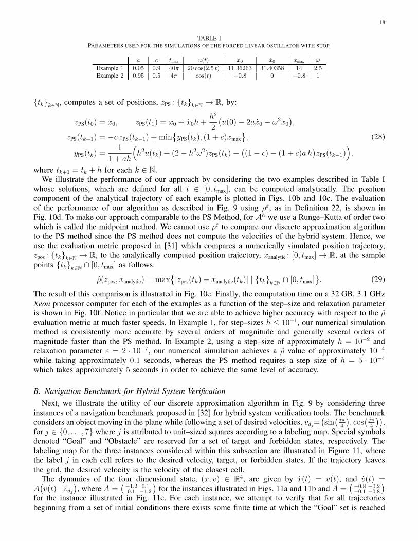
TABLE IPARAMETERS USED FOR THE SIMULATIONS OF THE FORCED LINEAR OSCILLATOR WITH STOP.
a c tmax u(t) x0 x0 xmax ω
Example 1 0.05 0.9 40π 20 cos(2.5 t) 11.36263 31.40358 14 2.5Example 2 0.95 0.5 4π cos(t) −0.8 0 −0.8 1
{tk}k∈N, computes a set of positions, zPS : {tk}k∈N → R, by:
zPS(t0) = x0, zPS(t1) = x0 + x0h+h2
2
(u(0)− 2ax0 − ω2x0
),
zPS(tk+1) = −c zPS(tk−1) + min{yPS(tk), (1 + c)xmax
},
yPS(tk) =1
1 + ah
(h2u(tk) + (2− h2ω2)zPS(tk)−
((1− c)− (1 + c)a h
)zPS(tk−1)
),
(28)
where tk+1 = tk + h for each k ∈ N.We illustrate the performance of our approach by considering the two examples described in Table I
whose solutions, which are defined for all t ∈ [0, tmax], can be computed analytically. The positioncomponent of the analytical trajectory of each example is plotted in Figs. 10b and 10c. The evaluationof the performance of our algorithm as described in Fig. 9 using ρε, as in Definition 22, is shown inFig. 10d. To make our approach comparable to the PS Method, for Ah we use a Runge–Kutta of order twowhich is called the midpoint method. We cannot use ρε to compare our discrete approximation algorithmto the PS method since the PS method does not compute the velocities of the hybrid system. Hence, weuse the evaluation metric proposed in [31] which compares a numerically simulated position trajectory,zpos : {tk}k∈N → R, to the analytically computed position trajectory, xanalytic : [0, tmax]→ R, at the samplepoints {tk}k∈N ∩ [0, tmax] as follows:
ρ(zpos, xanalytic) = max{|zpos(tk)− xanalytic(tk)| | {tk}k∈N ∩ [0, tmax]
}. (29)
The result of this comparison is illustrated in Fig. 10e. Finally, the computation time on a 32 GB, 3.1 GHzXeon processor computer for each of the examples as a function of the step–size and relaxation parameteris shown in Fig. 10f. Notice in particular that we are able to achieve higher accuracy with respect to the ρevaluation metric at much faster speeds. In Example 1, for step–sizes h ≤ 10−1, our numerical simulationmethod is consistently more accurate by several orders of magnitude and generally several orders ofmagnitude faster than the PS method. In Example 2, using a step–size of approximately h = 10−2 andrelaxation parameter ε = 2 · 10−7, our numerical simulation achieves a ρ value of approximately 10−4
while taking approximately 0.1 seconds, whereas the PS method requires a step–size of h = 5 · 10−4
which takes approximately 5 seconds in order to achieve the same level of accuracy.
B. Navigation Benchmark for Hybrid System VerificationNext, we illustrate the utility of our discrete approximation algorithm in Fig. 9 by considering three
instances of a navigation benchmark proposed in [32] for hybrid system verification tools. The benchmarkconsiders an object moving in the plane while following a set of desired velocities, vdj=
(sin(jπ4
), cos
(jπ4
)),
for j ∈ {0, . . . , 7} where j is attributed to unit–sized squares according to a labeling map. Special symbolsdenoted “Goal” and “Obstacle” are reserved for a set of target and forbidden states, respectively. Thelabeling map for the three instances considered within this subsection are illustrated in Figure 11, wherethe label j in each cell refers to the desired velocity, target, or forbidden states. If the trajectory leavesthe grid, the desired velocity is the velocity of the closest cell.
The dynamics of the four dimensional state, (x, v) ∈ R4, are given by x(t) = v(t), and v(t) =A(v(t)−vdj
), where A =
( −1.2 0.10.1 −1.2
)for the instances illustrated in Figs. 11a and 11b and A =
( −0.8 −0.2−0.1 −0.8
)for the instance illustrated in Fig. 11c. For each instance, we attempt to verify that for all trajectoriesbeginning from a set of initial conditions there exists some finite time at which the “Goal” set is reached

19
0 1 2 30
1
2
3
2
4
Obstacle
2
3
2
Goal
4
4
(a) Simple Instance
0 1 2 3 4 50
1
2
3
4
5
3
3
4
4
4
0
0
2
Goal
6
0
0
1
1
6
6
Obstacle
1
1
6
6
4
4
4
4
(b) Accuracy Instance
0 1 2 3 4 50
1
2
3
4
5
2
2
2
2
2
Goal
4
4
4
4
0
6
Obstacle
7
6
0
6
3
7
6
0
6
4
4
6
(c) Infinite Instance
Fig. 11. Navigation benchmark instances considered. Each instance map (symbols within each square) is shown with its desired velocity(drawn in each square with an arrow). Sample trajectories (drawn as lines beginning at filled in circles and ending at crosses) begin at someof the initial conditions which we attempt to verify.
while avoiding the “Obstacle” set. We perform this verification by discretizing over the given set of initialconditions.
For the instance illustrated in Fig. 11a, we select a set of initial conditions x ∈ [0, 1] × [0, 1] andv ∈ [0.1, 0.5]× [0.05, 0.25]. By choosing 10, 000 uniformly spaced points over the set of initial conditions,a step–size of 10−1, and relaxation size of 10−3, we are able to verify this system in approximately100 seconds. For the instance illustrated in Fig. 11b, we select a set of initial conditions x ∈ [3, 4]× [3, 4]and v ∈ [−1, 1] × [−1, 1]. This instance fails the verification task as trajectories are unable to reach the“Goal” set, but do not ever intersect with the “Obstacle” set. By choosing 10, 000 uniformly spaced pointsover the set of initial conditions, a step–size of 10−1, and relaxation size of 10−3, we discover that forthis system the task is not verifiable in approximately 85 seconds. For the instance illustrated in Fig. 11a,we select a set of initial conditions x ∈ [3, 3.5] × [3, 3.5] and v ∈ {0.5} × [−0.5, 0.5]. In this instance,verification is possible, but trajectories get close to the “Obstacle” set. By choosing 10, 000 uniformlyspaced points over the set of initial conditions, a step–size of 10−1, and relaxation size of 10−3, we areable to verify this system in approximately 210 seconds.
C. Simultaneous Transitions in Models of Legged LocomotionAs a terrestrial agent traverses an environment, its appendages intermittently contact the terrain. Since the
equations governing the agent’s motion change with each limb contact, the dynamics are naturally modeledby a controlled hybrid system with discrete modes corresponding to distinct contact configurations.Because the dynamics of dexterous manipulation are equivalent to that of legged locomotion [33], suchcontrolled hybrid systems model a broad and important class of dynamic interactions between an agentand environment.
Legged animals commonly utilize gaits that, on average, involve the simultaneous transition of multiplelimbs from aerial motion to ground contact [34], [35]. Similarly, many multi–legged robots enforce simulta-neous leg touchdown via virtual constraints implemented algorithmically [36], [37] or physical constraintsimplemented kinematically [38], [39]. Trajectories modeling such gaits pass through the intersection ofmultiple transition surfaces in the corresponding controlled hybrid system models. Therefore simulationof this frequently–observed behavior requires a numerical integration scheme that can accommodateoverlapping guards. The algorithm in Fig. 9 has this capability, and to the best of our knowledge isthe only existing algorithm possessing this property. We demonstrate this advanced capability using apronking gait in a saggital–plane locomotion model.
Fig. 12a contains an extension of the “Passive RHex–runner” in [40] that allows pitching motion. Arigid body with mass m and moment–of–inertia I moves in the saggital plane under the influence of

20
t = −0.5 t = −0.2 t = 0.0 t = 0.2 t = 0.5
(a) Schematic for the saggital–plane locomotion modelwith three mechanical degrees of freedom.
−π/8 0 +π/8θ
0.5
1.0
z
Dg
Dl
Dr
DaG(a,l)
G(l,g) G(a,r)
G(r,g)θ0 = 0
θ0 = −0.4
(b) Projection of guards in (θ, z) coordinates for transition from aerialdomain Da to ground domain Dg with parameters d = ` = 1,ψ = π/5.
Fig. 12. Schematic and discrete mode diagram for the saggital–plane locomotion model.
t = −0.5 t = −0.2 t = 0.0 t = 0.2 t = 0.5 t = −0.5 t = −0.2 t = 0.0 t = 0.2 t = 0.3
Fig. 13. Snapshots of pronk at discrete transition times from initial condition (x0, z0, θ0, x0, z0, θ0) = (0, 1.1, 0, 3.4, 0, 0), parameters(m, I, k, `, d, g, ψ) = (1, 1, 30, 1, 1, 9.81, π/5), step size h = 10−3, relaxation parameter ε = 10−2 (left). Same as before, but withθ0 = −0.4 (right).
gravity g. Linear leg–springs are attached to the body via a frictionless pin joint located symmetrically atdistance d/2 from the center–of–mass. The leg–springs are massless with linear stiffness k, rest length `,and make an angle ψ with respect to the body while in the air. When a foot touches the ground it attachesvia a frictionless pin joint, and it detaches when the leg extends to its rest length.
A pronk is a gait wherein all legs touch down and lift off from the ground at the same time [34], [35].Due to symmetries in our model, motion with pitch angle θ = 0 for all time is invariant. Therefore periodicorbits for the spring–loaded inverted pendulum model in [41] correspond exactly to pronking gaits forour model. Fig. 12b contains a projection of the guards G(a,l), G(a,r), G(l,g), G(r,g) in (θ, z) coordinates forthe transition from the aerial domain Da to the ground domain Dg through left stance Dl and right stanceDr. The pronking trajectory is illustrated by a downward–pointing vertical arrow, and a nearby trajectoryinitialized with negative rotational velocity is illustrated by a dashed line. Fig. 13 contains snapshots fromthese simulations.
The θ0 = 0 trajectory in Fig. 12b clearly demonstrates the need for a simulation algorithm that allowsthe intersection of multiple transition surfaces. We emphasize that our state–space metric was necessary toderive a convergent numerical approximation for this execution: since the discrete mode sequence differsfor any pair of trajectories arbitrarily close to the θ0 = 0 execution that pass through the interior of Dl andDr, respectively, a naıve application of the trajectory–space metric in [15] would yield a distance largerthan unity between the pair. Consequently no numerical simulation algorithm can be shown to convergeto the θ0 = 0 execution using a trajectory–space metric.
Another interesting property of this example is that it is possible to show (by carefully studying thetransitions between vector fields through the guards) that the hybrid quotient space M is a smooth6–dimensional manifold near the pronk execution, and that the piecewise–defined dynamics yield acontinuously–differentiable vector field on this quotient.
As a final note to practitioners, we remark that our algorithm does not require a specialized mechanism

21
to handle overlapping guards or control inputs: a single code will accurately simulate any orbitally stableexecution of the hybrid system under investigation, dramatically simplifying practical implementation.
VI. CONCLUSION
We developed an algorithm for the numerical simulation of controlled hybrid systems and proved theuniform convergence of our approximations to executions using a novel metrization of the controlled hybridsystem’s state space. The metric and the algorithm impose minimal assumptions on the hybrid systembeyond those required to guarantee existence and uniqueness of executions. Beyond their immediate utility,it is our conviction that these tools provide a foundation for formal analysis and computational controllersynthesis in hybrid systems.
REFERENCES
[1] A. Nerode and W. Kohn, “Models for hybrid systems: Automata, topologies, controllability, observability,” in Proceedings of theWorkshop on the Theory of Hybrid Systems, 1993, pp. 317–356.
[2] S. N. Simic, K. H. Johansson, J. Lygeros, and S. S. Sastry, “Towards a geometric theory of hybrid systems,” Dynamics of ContinuousDiscrete and Impulsive Systems Series B: Applications & Algorithms, vol. 12, no. 5/6, pp. 649–688, 2005.
[3] A. D. Ames and S. S. Sastry, “A homology theory for hybrid systems: Hybrid homology,” in Proceedings of the 8th InternationalWorkshop on Hybrid Systems: Computation and Control, 2005, pp. 86–102.
[4] K. H. Johansson, M. Egerstedt, J. Lygeros, and S. S. Sastry, “On the regularization of Zeno hybrid automata,” Systems & ControlLetters, vol. 38, no. 3, pp. 141–150, 1999.
[5] L. Tavernini, “Differential automata and their discrete simulators,” Nonlinear Analysis: Theory, Methods & Applications, vol. 11, no. 6,pp. 665–683, 1987.
[6] D. Gokhman, “Topologies for hybrid solutions,” Nonlinear Analysis: Hybrid Systems, vol. 2, no. 2, pp. 468–473, 2008.[7] D. Pollard, Convergence of Stochastic Processes, ser. Springer Series in Statistics. Springer, 1984.[8] C. Cai, R. Goebel, and A. R. Teel, “Relaxation results for hybrid inclusions,” Set-Valued Analysis, vol. 16, pp. 733–757, 2008.[9] R. G. Sanfelice and A. R. Teel, “Dynamical properties of hybrid systems simulators,” Automatica, vol. 46, no. 2, pp. 239–248, 2010.
[10] M. Carver, “Efficient integration over discontinuities in ordinary differential equation simulations,” Mathematics and Computers inSimulation, vol. 20, no. 3, pp. 190–196, 1978.
[11] L. F. Shampine, I. Gladwell, and R. W. Brankin, “Reliable solution of special problems for ODEs,” ACM Transactions on MathematicalSoftware, vol. 17, no. 1, pp. 11–25, 1991.
[12] J. Guckenheimer and A. Nerode, “Simulation for hybrid systems and nonlinear control,” in Proceedings of the 31st IEEE Conferenceon Decision and Control, 1992, pp. 2980–2981.
[13] J. Esposito, V. Kumar, and G. J. Pappas, “Accurate event detection for simulating hybrid systems,” in Proceedings of the 4th InternationalWorkshop on Hybrid Systems: Computation and Control, 2001, pp. 204–217.
[14] L. Paoli and M. Schatzman, “A numerical scheme for impact problems II: The multidimensional case,” SIAM journal on numericalanalysis, vol. 40, no. 2, pp. 734–768, 2003.
[15] L. Tavernini, “Generic asymptotic error estimates for the numerical simulation of hybrid systems,” Nonlinear Analysis: Hybrid Systems,vol. 3, no. 2, pp. 108–123, 2009.
[16] S. Burden, H. Gonzalez, R. Vasudevan, R. Bajcsy, and S. S. Sastry, “Numerical integration of hybrid dynamical systems via domainrelaxation,” in Proceedings of the 50th IEEE Conference on Decision and Control, 2011, pp. 3958–3965.
[17] J. L. Kelley, General Topology, ser. Graduate Texts in Mathematics. Springer, 1955.[18] J. Munkres, Topology. Prentice–Hall, 2000.[19] D. Burago, Y. Burago, and S. Ivanov, A Course in Metric Geometry, ser. Graduate Studies in Mathematics. American Mathematical
Society, 2001.[20] E. J. McShane, “Extension of range of functions,” Bulletin of the American Mathematical Society, vol. 40, no. 12, pp. 837–843, Jan
1934.[21] E. Polak, Optimization: Algorithms and Consistent Approximation, ser. Applied Mathematical Sciences. Springer, 1997.[22] G. Folland, Real Analysis: Modern Techniques and Their Applications, 2nd ed., ser. Pure and Applied Mathematics. John Wiley &
Sons, 1999.[23] J. M. Lee, Introduction to Smooth Manifolds, ser. Graduate Texts in Mathematics. Springer, 2003.[24] V. I. Utkin, “Variable structure systems with sliding modes,” IEEE Transactions on Automatic Control, vol. 22, no. 2, pp. 212–222,
1977.[25] A. F. Filippov, Differential Equations with Discontinuous Righthand Sides. Kluwer Academic Publishers, 1988.[26] J. Zhang, K. H. Johansson, J. Lygeros, and S. S. Sastry, “Zeno hybrid systems,” International Journal of Robust and Nonlinear Control,
vol. 11, no. 5, pp. 435–451, 2001.[27] J. Lygeros, K. H. Johansson, S. N. Simic, J. Zhang, and S. S. Sastry, “Dynamical properties of hybrid automata,” IEEE Transactions
on Automatic Control, vol. 48, no. 1, pp. 2–17, 2003.[28] W. P. Ziemer, Weakly Differentiable Functions, ser. Graduate Texts in Mathematics. Springer, 1989.[29] R. LeVeque, Finite Difference Methods for Ordinary and Partial Differential Equations: Steady–State and Time–Dependent Problems,
ser. Classics in Applied Mathematics. Society for Industrial and Applied Mathematics, 2007.[30] W. Rudin, Principles of Mathematical Analysis. McGraw–Hill, 1964.

22
[31] O. Janin and C. Lamarque, “Comparison of several numerical methods for mechanical systems with impacts,” International Journalfor Numerical Methods in Engineering, vol. 51, no. 9, pp. 1101–1132, 2001.
[32] A. Fehnker and F. Ivancic, “Benchmarks for hybrid systems verification,” in Proceedings of the 7th International Workshop on HybridSystems: Computation and Control, 2004, pp. 326–341.
[33] A. M. Johnson, G. C. Haynes, and D. E. Koditschek, “Standing self–manipulation for a legged robot,” in Proceedings of the IEEEInternational Conference on Intelligent Robots and Systems, 2012.
[34] R. M. Alexander, “The gaits of bipedal and quadrupedal animals,” The International Journal of Robotics Research, vol. 3, no. 2, pp.49–59, 1984.
[35] M. Golubitsky, I. Stewart, P. L. Buono, and J. J. Collins, “Symmetry in locomotor central pattern generators and animal gaits,” Nature,vol. 401, no. 6754, pp. 693–695, 1999.
[36] M. Raibert, M. Chepponis, and H. Brown Jr., “Running on four legs as though they were one,” IEEE Journal of Robotics and Automation,vol. 2, no. 2, pp. 70–82, 1986.
[37] U. Saranli, M. Buehler, and D. E. Koditschek, “RHex: A simple and highly mobile hexapod robot,” The International Journal ofRobotics Research, vol. 20, no. 7, pp. 616–631, 2001.
[38] S. Kim, J. Clark, and M. Cutkosky, “iSprawl: Design and tuning for high–speed autonomous open–loop running,” The InternationalJournal of Robotics Research, vol. 25, no. 9, pp. 903–912, 2006.
[39] A. Hoover, S. Burden, X. Fu, S. S. Sastry, and R. Fearing, “Bio–inspired design and dynamic maneuverability of a minimally actuatedsix–legged robot,” in Proceedings of the 3rd IEEE International Conference on Biomedical Robotics and Biomechatronics, 2010, pp.869–876.
[40] J. Seipel and P. Holmes, “Three–dimensional translational dynamics and stability of multi–legged runners,” The International Journalof Robotics Research, vol. 25, no. 9, pp. 889–902, 2006.
[41] R. M. Ghigliazza, R. Altendorfer, P. Holmes, and D. E. Koditschek, “A simply stabilized running model,” SIAM Journal on AppliedDynamical Systems, vol. 2, no. 2, pp. 187–218, 2003.


![RESEARCH ARTICLE Open Access Controlled expression of ......ecdysone controlled systems [14]. An improved version of the ecdysone-inducible approach is a two-hybrid ver-sion, also](https://static.fdocuments.us/doc/165x107/60cdfe486cb19b23041f3d6e/research-article-open-access-controlled-expression-of-ecdysone-controlled.jpg)