1 MATERIAL REDUCTION REDUCTION OF FORMWORK … · THE SHAPE OF BENDING Conventional concrete beams...
7
COLUMN FORMWORK Fabric column formwork is hundreds of times lighter than conventional formwork. A simple tube of fabric will suffice. [1] illustrates how two flat rectangles of fabric can form variable profile columns. [2] shows a formwork design used to cast 13 complex columns in Puerto Rico - each one a different height, varying in diameter from 30cm to 40cm, and each with its own individual capital design. [3] shows the formwork for all 13 columns (including 4 spares) which were made in Canada and flown as checked luggage to Puerto Rico in three small bags. This huge reduction in formwork material and weight produces dramatically new logistical freedoms. BEAM FORMWORK [4] shows one method of casting a variable section beam in a flat rectangle of fabric. The same piece of fabric can be re-used to form a multitude of different casts (precast or cast-in- place). Edge splines (A) are inserted into hems sewn along the edges. A sacrificial bottom spline (B) vertically pre-tensions the fabric to give a more efficient “V” section (this bottom spline is not used as reinforcing). [6] shows the edge splines being pulled into place. [5] shows the formwork used to cast the 12 metre long, double cantilever beam shown in [15] & [16]. [7] shows the role of fabric used to cast this 12 m beam. This fabric sheet weighs only 10 Kg. The material cost was $50 CN, plus another $50 CN to have hems sewn along its edges. Total cost = approx. $75 U.S. This formwork is entirely reusable (including the tables which never touch any concrete). IMPROVED FORMWORK FOR CASTING BEAMS The 5 m beam shown in [8] was cast in the geotextile fabric sheet shown in [10]. This fabric weighs 3 Kg and cost $8 US. Concrete does not adhere to these fabrics, eliminating the need for release oils. Although the maximum number of re-use cycles is unknown, formwork fabrics will easily outlast wood: one polyethylene geotextile mold has been used 15 times with no significant degradation. [9] shows a method of pulling the fabric edges using wood blocks and conventional fasteners. This method eliminates sewing, thus reducing costs and limiting tools to those that are native to “construction culture”. Another method for further reducing formwork materials replaces the “tables” shown in [4] & [5] above with 2 steel pipes [12] & [13]. This simple, reusable, pipe-frame quickly and easily adapts to form different lengths, widths, and depths using the same fabric sheet. This rig is the first to achieve a 24 hr. production cycle (the standard in the pre-cast industry). [11] shows an alternate method for shaping curved beams that does not require a sacrificial spline at the bottom of the formwork: This method uses a rigid “keel”, cut to define the bending moment curve of the beam (see Panel 2). In this method two flat rectangular sheets of fabric are sandwiched (left and right) between the two halves of this keel. The fabric is pulled up to the pipes (or tables), to vertically pre- tension the formwork, thus providing an efficiently shaped, lightweight beam with great dimensional accuracy. SCULPTURES FORM STUDIES DRAWINGS TEST CONSTRUCTIONS 1989-2001 REDUCTION OF FORMWORK MATERIALS [1] MATERIAL REDUCTION NA05_CEJNW_00022 HEAVY RIGID FORMWORK STRUCTURES REPLACED BY LIGHT INEXPENSIVE POLYOLIFIN GEOTEXTILE FABRICS [ [1] Columnformworkdiagram [2] Casa Dent column formwork [3] Formwork for 17 columns transported as luggage [4] Formwork method for variable section beam [5] Formwork for 12-metre beam shown in [15] & [16] [7] 10 kg formwork for a 12-metre beam: $75 US [8] 5 meter proof-of-concept beam [9] Connections without sewing [10] 3 kg. formwork for a 5-metre beam [8]: $8 US [6] Pulling the edge spline [11] “Keel” formwork method using two flat rectangular sheets [12] Adjustable pipe-stands replace “tables” [4] & [5] used in earlier rigs [13] Pipe-stand rig: a new beam every 24hrs.
Transcript of 1 MATERIAL REDUCTION REDUCTION OF FORMWORK … · THE SHAPE OF BENDING Conventional concrete beams...

COLUMN FORMWORKFabric column formwork is hundreds of times lighter than conventional formwork. A simple tube of fabric will suffice. [1] illustrates how two flat rectangles of fabric can form variable profile columns. [2] shows a formwork design used to cast 13 complex columns in Puerto Rico - each one a different height, varying in diameter from 30cm to 40cm, and each with its own individual capital design. [3] shows the formwork for all 13 columns (including 4 spares) which were made in Canada and flown as checked luggage to Puerto Rico in three small bags. This huge reduction in formwork material and weight produces dramatically new logistical freedoms.
BEAM FORMWORK[4] shows one method of casting a variable section beam in a flat rectangle of fabric. The same piece of fabric can be re-used to form a multitude of different casts (precast or cast-in-place). Edge splines (A) are inserted into hems sewn along the edges. A sacrificial bottom spline (B) vertically pre-tensions the fabric to give a more efficient “V” section (this bottom spline is not used as reinforcing). [6] shows the edge splines being pulled into place.
[5] shows the formwork used to cast the 12 metre long, double cantilever beam shown in [15] & [16]. [7] shows the role of fabric used to cast this 12 m beam. This fabric sheet weighs only 10 Kg. The material cost was $50 CN, plus another $50 CN to have hems sewn along its edges. Total cost = approx. $75 U.S. This formwork is entirely reusable (including the tables which never touch any concrete).
IMPROVED FORMWORK FOR CASTING BEAMSThe 5 m beam shown in [8] was cast in the geotextile fabric sheet shown in [10]. This fabric weighs 3 Kg and cost $8 US. Concrete does not adhere to these fabrics, eliminating the need for release oils. Although the maximum number of re-use cycles is unknown, formwork fabrics will easily outlast wood: one polyethylene geotextile mold has been used 15 times with no significant degradation.
[9] shows a method of pulling the fabric edges using wood blocks and conventional fasteners. This method eliminates sewing, thus reducing costs and limiting tools to those that are native to “construction culture”.
Another method for further reducing formwork materials replaces the “tables” shown in [4] & [5] above with 2 steel pipes [12] & [13]. This simple, reusable, pipe-frame quickly and easily adapts to form different lengths, widths, and depths using the same fabric sheet. This rig is the first to achieve a 24 hr. production cycle (the standard in the pre-cast industry).
[11] shows an alternate method for shaping curved beams that does not require a sacrificial spline at the bottom of the formwork: This method uses a rigid “keel”, cut to define the bending moment curve of the beam (see Panel 2). In this method two flat rectangular sheets of fabric are sandwiched (left and right) between the two halves of this keel. The fabric is pulled up to the pipes (or tables), to vertically pre-tension the formwork, thus providing an efficiently shaped, lightweight beam with great dimensional accuracy.
SCULPTURESFORM STUDIESDRAWINGSTEST CONSTRUCTIONS1989-2001
REDUCTION OF FORMWORK MATERIALS[1]MATERIAL REDUCTION NA05_CEJNW_00022
HEAVY RIGID FORMWORK STRUCTURES REPLACED BY LIGHT INEXPENSIVE POLYOLIFIN GEOTEXTILE FABRICS
[
[1] Column formwork diagram [2] Casa Dent column formwork [3] Formwork for 17 columns transported as luggage
[4] Formwork method for variable section beam
[5] Formwork for 12-metre beam shown in [15] & [16]
[7] 10 kg formwork for a 12-metre beam: $75 US
[8] 5 meter proof-of-concept beam [9] Connections without sewing [10] 3 kg. formwork for a 5-metre beam [8]: $8 US
[6] Pulling the edge spline
[11] “Keel” formwork method using two flat rectangular sheets
[12] Adjustable pipe-stands replace “tables” [4] & [5] used in earlier rigs
[13] Pipe-stand rig: a new beam every 24hrs.

THE SHAPE OF BENDINGConventional concrete beams are generally rectangular because the economy of rigid formwork demands uniform-section prismatic shapes. These shapes, however, are highly inefficient. The most materially efficient shape will follow the beam’s bending moment diagram (as in a suspension bridge). [14] shows the bending moment diagram for a uniformly loaded, double cantilever, 12 m beam superimposed on the longitudinal profile of the beam. This variable-section beam follows the shape of its own bending resistance by placing structural material only along the “naturally flowing” force path for its load (see Panel 4).
This strategy for minimizing structural materials is well known and commonly used in long-span structures where reduction of dead-weight is most important. It is not used in concrete buildings, however, because the economy of mold-making dominates in these shorter span structures. Flexible formworks, however, radically change this economy by allowing naturally curved beams to be easily and economically cast.
It is projected that “bending moment” beams, such as those shown in [8], [15], [16], & [22], will require less than half the concrete of equivalent rectangular beams. Reducing material in this way cuts the embodied energy, dead-weight, and material costs of these beams in half. Dead weight reductions ‘cascade’ throughout the entire structural system providing further savings in material and embodied energy - particularly in the foundations.
[16] graphically illustrates the concrete saved in a bending moment shaped beam. The transverse sections of this beam also vary to minimize concrete in the tension zones while feeding concrete to the compression zones, further reducing concrete volume. Forming a beam in this way is not difficult using a flexible fabric form. The beam shown in [15] & [16] was cast in a single flat rectangle of fabric (see [4] & [5] - Panel 1) that easily adopts these efficient curves through a strategic pre-tensioning of the fabric. Further simplifications of the method are also being developed. This method can be used in both precast and cast-in-place construction.
AN AESTHETICS OF NECESSITYThe curved tension geometries obtained by fabric formworks offer new architectural possibilities. These naturally produced curved geometries suggest a “yielding approach” where form is ‘given’ as much as it is ‘designed’. These sculptural and structural forms have a “biomimetic” aspect; they are formed by the imperatives of natural law, and recall the forms of living things. In their simplicity and richness they suggest an ‘aesthetics of necessity’ (see Project Booklet Criteria #5). This re-focusing of architectural intent offers a new language of form that is well attuned to the urgencies and aesthetics of a sustainable architecture.
REDUCTION OF CONCRETE IN BEAMS-1[2]MATERIAL REDUCTION NA05_CEJNW_00022
LIGHTER AND MORE EFFICIENT STRUCTURES FORMED BY FOLLOWING NATURAL STRUCTURAL CURVES
[14] Longitudinal profile of a 12 metre, double-cantilever beam superimposed on its bending moment diagram
[15] 12 metre reinforced concrete beam cast from a single rectangular sheet of geotextile fabric (see Panel 1: [5] & [7])
[16] Concrete saved by a variable section, fabric-formed beam
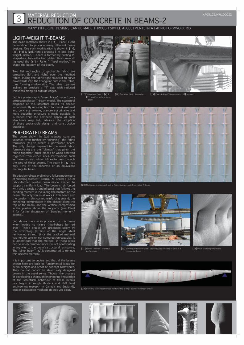
LIGHT-WEIGHT T-BEAMSThe basic methods shown in [11] - Panel 1 can be modified to produce many different beam designs. One such modification is shown in [17], [18], [19] & [20]. Here a precast 5 m long, light-weight, ribbed, T-beam is formed by cutting V-shaped notches in the two tables. This formwork rig used the [11] - Panel 1 “keel method” to shape the bottom of the beam.
Two flat rectangles of geotextile fabric are stretched (left and right) over the modified tables. Pulling the fabric tight causes it to curve downwards into the triangular cuts in the table, thus forming shallow ribs. The table tops are inclined to produce a “T” slab with reduced thickness along its outside edges.
[20] is a photographic ‘assemblage’ made from a prototype plaster T-beam model. The sculptural elegance of this structure belies its deeper economies. By reducing both formwork material and concrete volume, a more sustainable and more beautiful structure is made possible. It is hoped that the aesthetic appeal of such structures may help advance the adoption of these sustainable design and construction practices.
PERFORATED BEAMSThe beam shown in [22] reduces concrete volumes even further by “pinching” the fabric formwork [21] to create a perforated beam. The only change required to the usual fabric formwork rig are the “clamps” that pinch the fabric together (small pieces of wood screwed together from either side). Perforations such as these can also allow utilities to pass through the web of these beams. The beam in [22] has only 38% of the concrete of an equivalent rectangular beam.
This design follows preliminary failure mode tests of “bending moment” beams. [24] shows a 1.5 m fabric-formed plaster beam model shaped to support a uniform load. This beam is reinforced with only a single strand of steel that follows the bending moment curve along the bottom of the beam. The only forces at work in this beam are: the tension in this curved reinforcing strand; the horizontal compression in the plaster along the top of the beam; and the vertical compression in the plaster above the supports (see Panel 4 for further discussion of “bending moment” beams).
[24] shows the cracks produced in this beam when loaded to failure (highlighted by red lines). These cracks are produced solely by the stretching (strain) of the single steel reinforcing strand. Since the cracked material has neither tension nor compression capacity, it is understood that the material in these areas can be safely removed since it is not contributing in any way to the beam’s structural resistance. The “pinch beam” [22] is constructed to remove this useless material.
It is important to understand that all the beams shown here are built as fundamental ideas for beam designs and proof-of-concept formworks. They do not constitute structurally designed beams in the usual sense. Though the process of developing a thorough engineering knowledge of the structural behaviour of these beams has begun (through Masters and PhD level engineering research in Canada and England), proper calculation methods do not yet exist.
REDUCTION OF CONCRETE IN BEAMS-2[3]MATERIAL REDUCTION NA05_CEJNW_00022
MANY DIFFERENT DESIGNS CAN BE MADE THROUGH SIMPLE ADJUSTMENTS IN A FABRIC FORMWORK RIG
[17] Tables (see Panel 1: [4] & [5]) modified to form ribbed T-beam
[18] Stretched fabric, forms ribs [19] View of ribbed T-beam cast in [18] formwork
[20] Photographic drawing of roof or floor structure made from ribbed T-Beams
[21] Fabrics “pinched” to create perforations.
[22] 5-metre perforated “pinch” beam reduces concrete to 38% of a rectangular beam
[23] Detail of beam perforations
[24] Uniformly loaded beam model reinforced by a single strand: no “shear” cracks

STRUCTURAL SIMPLICITYWhen the shape of a structure changes, the “shape“ or “flow” of its internal forces also changes. Curved beams do not behave like rectangular beams. In order to understand the basic structural behaviour of these curved beam shapes, simple physical models were constructed using cardboard and foam rubber. [25], [26] & [27] show these didactic beam models loaded with bricks.
A regular grid of circles is printed on the foam rubber web of these beams to help visualize the internal forces. [25] & [26] show the classic web deformation patterns for a rectangular beam: In the middle portion of the span all the circles in the web are undisturbed, indicating that tension and compression forces are confined to the top and bottom cardboard ‘flanges’. Near the supports, however, both tension and compression forces leave the cardboard flanges to ‘flow’ diagonally towards their respective supports (tension rising up, and compression arching down). These diagonal tension forces make a conventional rectangular concrete beam vulnerable to failure near the supports through “shear cracking”. To resist this diagonal tension, conventional beams are constructed with numerous, more or less closely spaced, vertical reinforcing “stirrups”.
[27] shows a uniformly loaded beam that is half rectangular and half parabolic in shape. There are two important things to notice about this beam: 1. The circles in the web of the parabolic half are not deformed, and 2. The deflection is greater in the rectangular half. The lack of deformation in the web shows that the tension and compression forces in this beam are confined to the top and bottom cardboard flanges. The greater deflection in the rectangular half is caused by the tension and compression forces leaving the stiffer cardboard flanges and entering (and deforming) the less resistant foam rubber web.
These simple physical models predict that a beam with a depth that varies in proportion to its bending moment will not develop diagonal tension (“shear” stresses) in its ‘web’ material. In other words, all the tension forces in such a beam may be confined to a single reinforcing strand following the bending moment-shaped curve. This scenario assumes that the beam’s internal forces resolve at its supports in a structural “node”, as in a truss [33] [34] [35]- Panel 5 for details of this structural node).
Before discussing the “real world” factors that complicate this theoretical proposition, let us first examine a full-scale test of this theory. [28] is a failure-mode test of a uniformly loaded 5 m concrete beam reinforced with one 15mm steel rebar. [29] is a similar beam but loaded with a single concentrated load at the centre of its span. Neither of these beams developed diagonal tension cracks. As predicted by our smaller physical models, all the tension forces in these beams are confined to the single reinforcing bar along the bottom. Even the beam in [29], which is loaded “wrong” for its shape (the bending moment for a concentrated load would dictate a triangular beam) did not develop diagonal tension cracks. The complete lack of cracks near the supports confirms the existence of a structural “node” at this point (See Annex for structural test information).
15
REDUCTION OF REINFORCING STEEL IN BEAMS-1[4]MATERIAL REDUCTION NA05_CEJNW_00022
MORE EFFICIENT STRUCTURAL SHAPES MAY CHANNEL INTERNAL FORCES THROUGH FEWER PIECES OF STEEL
[25] Foam-rubber beam model showing web deformations [26] Detail of web deformations in a rectangular beam
[27] Model showing no deformation (i.e. no forces) in the web of a bending moment shaped beam.
[28] Failure mode test – Uniform Load: a beam with a depth varying in proportion to its bending moment does not develop “shear” cracks
[29] Failure mode test - Concentrated Load: absence of “shear” cracks suggests ability to withstand variable “incorrect” loading

SIMPLIFYING CONSTRUCTION - SOME NEW QUESTIONS[5]MATERIAL REDUCTION NA05_CEJNW_00022
FEWER PIECES: THE PROSPECT OF SIGNIFICANTLY SIMPLIFIED CONCRETE BEAM CONSTRUCTION EXAMINED
[30] Installation of the 15mm rebar in a 5-metre test beam [31] Detail of rebar being pulled down (note rope) to form curved shape
[33] Diagram of reinforcement location: Blue = flexure reinforcing; Green = possible “shear” reinforcing; Red = compression concrete (Overall diagram shows reduced concrete volume in “bending moment” beam)
[32] Diagram of structural “node” created at supports
[34] Construction detail of support point “node”: rebar welded to “end cap” [35] Construction detail of support point “node”: “post-tensioning strand at end cap”
CONSTRUCTION DETAILS The blue line in [32] & [33] shows the location of the primary reinforcing for a simply supported beam. Its installation is shown in [30] & [31]: A straight 15mm rebar is pulled to the bottom of the form. Circular 40mm plastic “chairs” ensure standard fire-cover for the steel.
The ends of the reinforcing bar are welded to steel angle end caps [34], ensuring that a structural “node” is formed at the beam’s supports. [32] illustrates this node condition. [35] shows this end condition with a post-tension reinforcing strand. Other (less crude) details for achieving a nodal transfer of forces at the supports are also being investigated.
RESEARCH REFLECTIONS AND QUESTIONS RAISED:The prospect of concrete beams using minimal concrete and only a few simple pieces of steel is compelling. Such a radical re-thinking of reinforced concrete beam design, however, requires serious consideration. The complexity of a beam’s behaviour in its actual service life raises many important questions that must be carefully investigated. We will soon have some more definitive insights from Masters and PhD level engineering research recently initiated at the University of Manitoba and associated investigations at the University of Edinburgh, and Bath University in the U.K.
Basic theory tells us that diagonal tension (“shear”) stresses will not occur in beams correctly configured for their load, however, a beam shaped for a specific load will nearly always be loaded “incorrectly” in service. Under what conditions might such beams develop diagonal tension (“shear”) cracks, and how sensitive will ‘bending moment’ beams be to different “incorrect” loading patterns or the inevitable deviations from an ideal geometry?
The behaviour of a parabolic beam subjected to a concentrated load [29] is encouraging, but far from definitive. What about other “incorrect” loading patterns? Under what loading conditions will a ‘bending moment’ shaped beam be most vulnerable to “shear” cracking?
To date, only very flexible under-reinforced beams have been tested. Will diagonal “shear” cracks only develop in stiffer beams that are less likely to fail first in bending?
Where it may be required, “shear” reinforcing can be economically provided, though not in the usual way. Conventional “shear” reinforcing stirrups are not an option where the size and shape of such stirrups would change constantly across the span. However, additional straight bars hung longitudinally along potential lines of diagonal tension have proven quite easy to construct. The schematic location of this potential “shear” reinforcing is shown by the green lines in [33].
Unlike beams with a uniform depth, strains in bending moment beams are uniformly high across their entire span. This will likely make deflection an important limiting factor. Suitable stiffness may be provided by increasing the area of reinforcing steel (or by post-tensioning). Though flexible, these beams show themselves to be quite robust, sustaining dramatic deflections without physical failure [28].
FABRIC-FORMED PANELS AND THIN SHELLS-1[6]MATERIAL REDUCTION NA05_CEJNW_00022
PRE-CAST OR TILT-UP CONCRETE PANELS: USED AS MOLDS FOR THIN FUNICULAR COMPRESSION SHELLS
[36] Funicular tension geometries produced in loaded fabric membranes can be used to cast funicular compression shells
[37] Fabric-cast concrete panel used as a mold for the shell panel in [38]
[38] Funicular compression shell panel cast from the [37] fabric-cast panel
[39] Light wooden lower frame and supports for a fabric-cast panel rig [40] Geotextile membrane stretched over the [39] frame
[41] Concrete Panel cast from the [39] & [40] formwork rig [42] Thin-shell panel cast from the [41] fabric-cast panel
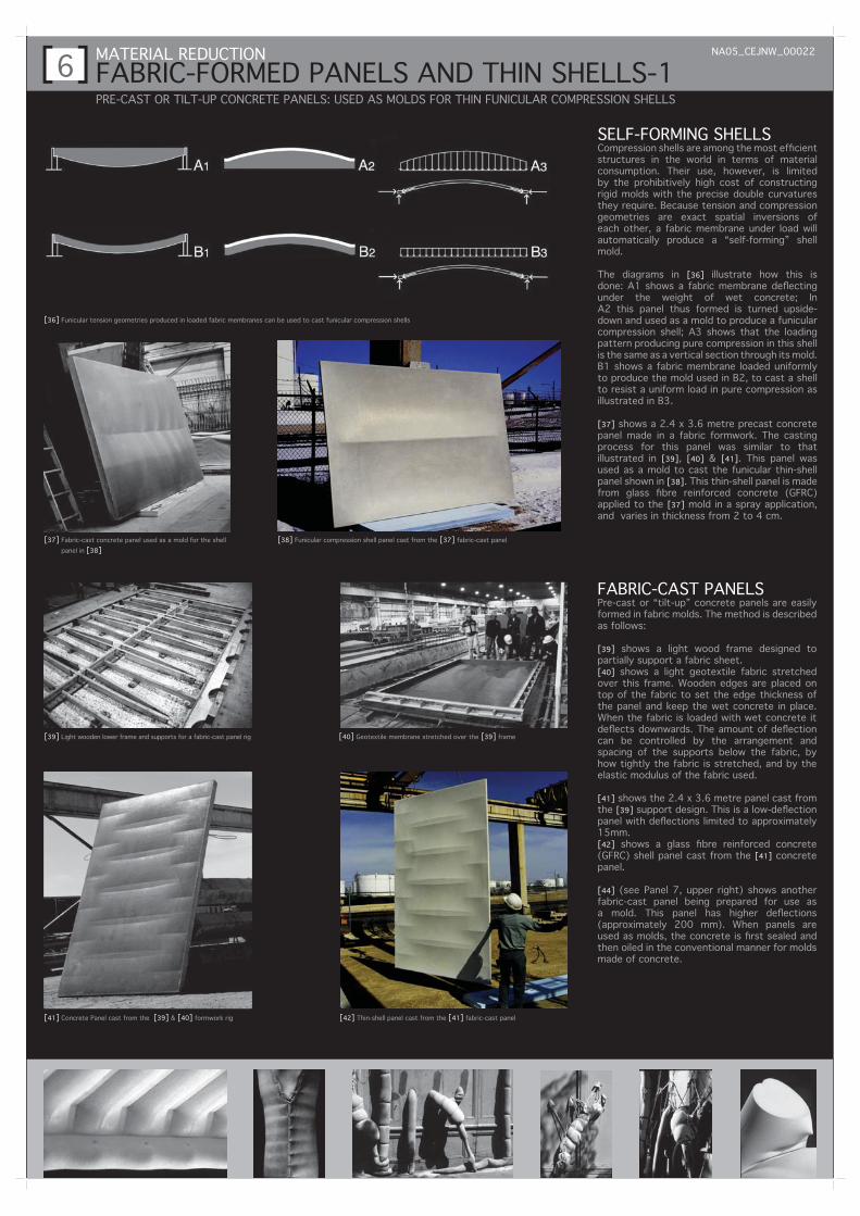
SELF-FORMING SHELLSCompression shells are among the most efficient structures in the world in terms of material consumption. Their use, however, is limited by the prohibitively high cost of constructing rigid molds with the precise double curvatures they require. Because tension and compression geometries are exact spatial inversions of each other, a fabric membrane under load will automatically produce a “self-forming” shell mold.
The diagrams in [36] illustrate how this is done: A1 shows a fabric membrane deflecting under the weight of wet concrete; In A2 this panel thus formed is turned upside-down and used as a mold to produce a funicular compression shell; A3 shows that the loading pattern producing pure compression in this shell is the same as a vertical section through its mold. B1 shows a fabric membrane loaded uniformly to produce the mold used in B2, to cast a shell to resist a uniform load in pure compression as illustrated in B3.
[37] shows a 2.4 x 3.6 metre precast concrete panel made in a fabric formwork. The casting process for this panel was similar to that illustrated in [39], [40] & [41]. This panel was used as a mold to cast the funicular thin-shell panel shown in [38]. This thin-shell panel is made from glass fibre reinforced concrete (GFRC) applied to the [37] mold in a spray application, and varies in thickness from 2 to 4 cm.
FABRIC-CAST PANELSPre-cast or “tilt-up” concrete panels are easily formed in fabric molds. The method is described as follows:
[39] shows a light wood frame designed to partially support a fabric sheet.[40] shows a light geotextile fabric stretched over this frame. Wooden edges are placed on top of the fabric to set the edge thickness of the panel and keep the wet concrete in place. When the fabric is loaded with wet concrete it deflects downwards. The amount of deflection can be controlled by the arrangement and spacing of the supports below the fabric, by how tightly the fabric is stretched, and by the elastic modulus of the fabric used.
[41] shows the 2.4 x 3.6 metre panel cast from the [39] support design. This is a low-deflection panel with deflections limited to approximately 15mm.[42] shows a glass fibre reinforced concrete (GFRC) shell panel cast from the [41] concrete panel.
[44] (see Panel 7, upper right) shows another fabric-cast panel being prepared for use as a mold. This panel has higher deflections (approximately 200 mm). When panels are used as molds, the concrete is first sealed and then oiled in the conventional manner for molds made of concrete.
FABRIC-FORMED PANELS AND THIN SHELLS-2[7]MATERIAL REDUCTION NA05_CEJNW_00022
MULTIPLE DESIGNS FROM A SINGLE FABRIC SHEET/ DIRECT- CAST COMPRESSION VAULTS/ COMPUTER MODELS
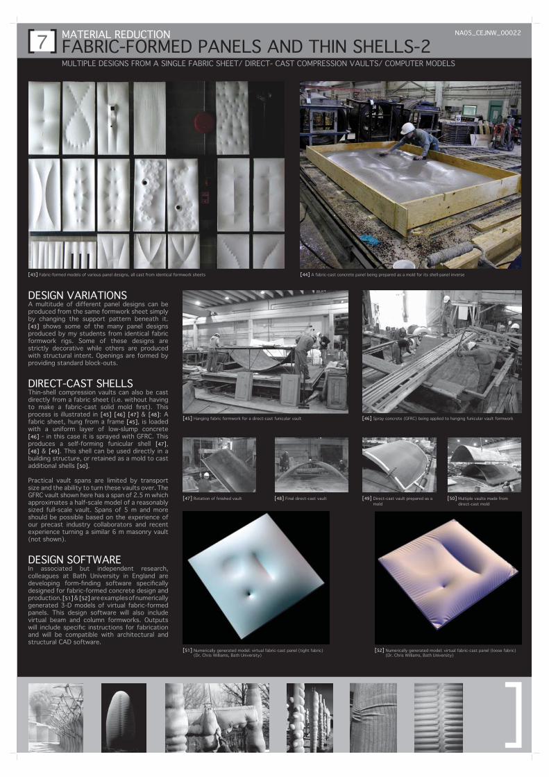
[44] A fabric-cast concrete panel being prepared as a mold for its shell-panel inverse
[46] Spray concrete (GFRC) being applied to hanging funicular vault formwork
[47] Rotation of finished vault [48] Final direct-cast vault [49] Direct-cast vault prepared as a mold
[50] Multiple vaults made from direct-cast mold
[51] Numerically generated model: virtual fabric-cast panel (tight fabric) (Dr. Chris Williams, Bath University)
[43] Fabric-formed models of various panel designs, all cast from identical formwork sheets
[45] Hanging fabric formwork for a direct-cast funicular vault
[52] Numerically generated model: virtual fabric-cast panel (loose fabric) (Dr. Chris Williams, Bath University)
DESIGN VARIATIONSA multitude of different panel designs can be produced from the same formwork sheet simply by changing the support pattern beneath it. [43] shows some of the many panel designs produced by my students from identical fabric formwork rigs. Some of these designs are strictly decorative while others are produced with structural intent. Openings are formed by providing standard block-outs.
DIRECT-CAST SHELLSThin-shell compression vaults can also be cast directly from a fabric sheet (i.e. without having to make a fabric-cast solid mold first). This process is illustrated in [45] [46] [47] & [48]: A fabric sheet, hung from a frame [45], is loaded with a uniform layer of low-slump concrete [46] - in this case it is sprayed with GFRC. This produces a self-forming funicular shell [47], [48] & [49]. This shell can be used directly in a building structure, or retained as a mold to cast additional shells [50].
Practical vault spans are limited by transport size and the ability to turn these vaults over. The GFRC vault shown here has a span of 2.5 m which approximates a half-scale model of a reasonably sized full-scale vault. Spans of 5 m and more should be possible based on the experience of our precast industry collaborators and recent experience turning a similar 6 m masonry vault (not shown).
DESIGN SOFTWAREIn associated but independent research, colleagues at Bath University in England are developing form-finding software specifically designed for fabric-formed concrete design and production. [51] & [52] are examples of numerically generated 3-D models of virtual fabric-formed panels. This design software will also include virtual beam and column formworks. Outputs will include specific instructions for fabrication and will be compatible with architectural and structural CAD software.
[