1 Linear Precoding for Multi-Pair Two-Way MIMO Relay Systems with
26
1 Linear Precoding for Multi-Pair Two-Way MIMO Relay Systems with Max-Min Fairness Meixia Tao, Senior Member, IEEE and Rui Wang Abstract Two-way relaying has demonstrated significant gain in spectral efficiency by applying network coding when a pair of source nodes exchange information via a relay node. This paper is concerned with the scenario where multiple pairs of users exchange information through a common relay node equipped with multiple antennas. We aim to design linear precoding at the relay based on amplify-and- forward strategy. The goal is to maximize the minimum achievable rate among all the users subject to a peak relay power constraint so as to achieve the max-min fairness. We first convert this non- convex problem into a series of semidefinite programming problems using bisection search and certain transformation techniques. A quasi-optimal solution is then obtained by using semidefinite relaxation (SDR). To reduce the design complexity, we further introduce a pair-wise zero-forcing (ZF) structure that eliminates the interference among different user pairs. By applying this structure, the precoding design problem is simplified to a power allocation problem which can be optimally solved. A simplified power allocation algorithm is also proposed. Simulation results show that the proposed SDR-based precoding not only achieves high minimum user rate but also maintains good sum-rate performance when compared with existing schemes. It is also shown that the proposed pair-wise ZF precoding with simplified power allocation strikes a good balance between performance and complexity. Index Terms Multiple-input multiple-output (MIMO), precoding, two-way relaying, non-regenerative relay, mul- tiuser. Copyright (c) 2011 IEEE. Personal use of this material is permitted. However, permission to use this material for any other purposes must be obtained from the IEEE by sending a request to [email protected]. The authors are with the Department of Electronic Engineering at Shanghai Jiao Tong University, Shanghai, 200240, P. R. China. Emails:{mxtao, liouxingrui}@sjtu.edu.cn. This work is supported by the National Natural Science Foundation of China under grant 60902019, the Program for New Century Excellent Talents in University (NCET) under grant NCET-11-0331, and the Innovation Program of Shanghai Municipal Education Commission under grant 11ZZ19.
Transcript of 1 Linear Precoding for Multi-Pair Two-Way MIMO Relay Systems with
1
Linear Precoding for Multi-Pair Two-Way
MIMO Relay Systems with Max-Min Fairness
Meixia Tao, Senior Member, IEEE and Rui Wang
Abstract
Two-way relaying has demonstrated significant gain in spectral efficiency by applying network
coding when a pair of source nodes exchange information via a relay node. This paper is concerned
with the scenario where multiple pairs of users exchange information through a common relay node
equipped with multiple antennas. We aim to design linear precoding at the relay based on amplify-and-
forward strategy. The goal is to maximize the minimum achievable rate among all the users subject
to a peak relay power constraint so as to achieve the max-min fairness. We first convert this non-
convex problem into a series of semidefinite programming problems using bisection search and certain
transformation techniques. A quasi-optimal solution is then obtained by using semidefinite relaxation
(SDR). To reduce the design complexity, we further introduce a pair-wise zero-forcing (ZF) structure
that eliminates the interference among different user pairs. By applying this structure, the precoding
design problem is simplified to a power allocation problem which can be optimally solved. A simplified
power allocation algorithm is also proposed. Simulation results show that the proposed SDR-based
precoding not only achieves high minimum user rate but also maintains good sum-rate performance
when compared with existing schemes. It is also shown that the proposed pair-wise ZF precoding with
simplified power allocation strikes a good balance between performance and complexity.
Index Terms
Multiple-input multiple-output (MIMO), precoding, two-way relaying, non-regenerative relay, mul-
tiuser.
Copyright (c) 2011 IEEE. Personal use of this material is permitted. However, permission to use this material for any other
purposes must be obtained from the IEEE by sending a request to [email protected].
The authors are with the Department of Electronic Engineering at Shanghai Jiao Tong University, Shanghai, 200240, P. R.
China. Emails:{mxtao, liouxingrui}@sjtu.edu.cn.
This work is supported by the National Natural Science Foundation of China under grant 60902019, the Program for New
Century Excellent Talents in University (NCET) under grant NCET-11-0331, and the Innovation Program of Shanghai Municipal
Education Commission under grant 11ZZ19.
2
I. INTRODUCTION
A wireless propagation channel possesses two basic features: broadcasting and multiple-access.
As a result, the transmit signal on a certain link can be detected by other neighboring nodes in
the wireless network and these nodes then can act as relays and help to forward the message
to the destination receiver. Such process leads to the basic idea of cooperative communications,
which now has received great attention from both academia and industry. Unlike the design
of traditional wireless communication systems where users compete with each other to access
wireless resources, cooperative communications enable user cooperation and resource sharing
at the physical layer and hence can significantly enhance the system performance. Network
coding [1], on the other hand, as a significant technical breakthrough in network communication,
allows a network router to perform coding on multiple data packets so that the information
contained in multiple packets can be embedded in one coded packet. By doing this, the network
throughput can be increased significantly. While network coding is initially proposed for wired
networks, its application in wireless networks is more promising due to the broadcast nature of
wireless channels. Naturally, the combination of cooperative communication and network coding
is believed to be a key technique to dramatically enhance the performance of wireless networks
and even change the network architecture of further wireless networks.
A building block of wireless networks where network coding meets cooperative communica-
tion is the two-way relay channel [2]–[4], where two source nodes exchange information with
each other via a relay node. Two-way relaying applies the principle of network coding at the
relay node so as to mix the signals received from the two source nodes and then employs at each
destination the self-interference (SI) cancelation technique to extract the desired information.
While most of the existing works on two-way relaying in the literature focus on the simplest
two-user model, two-way relaying protocol can be generalized to a more complex model where
multiple users simultaneously exchange information through a relay node. A major challenge of
designing a multiuser two-way relay system (MU-TWRS) arises from the inter-user interference
which may dramatically degrade the system performance if not handled properly.
A simple method to avoid inter-user interference in MU-TWRS is to let different users transmit
on orthogonal channels, for example, by using the code-division-multiple-access (CDMA) [5]
or orthogonal-frequency-division-multiple-access (OFDMA) [6]. A more advanced method to

3
suppress inter-user interference is to apply the multiple-input multiple-output (MIMO) technique
so that the multiuser transmission can be achieved over the same frequency domain, also referred
to as space-division-multiple-access (SDMA) as in [7]–[13]. Therein, it is critical to design the
transceiver or precoder at each multi-antenna node, especially the relay node. In [7], [8], the
linear relay precoding under decode-and-forward (DF) relay strategy is studied. Since the relay is
assumed to fully decode the received signals in the first time slot, the relay precoding only affects
the performance of transmission in the second time slot. Therefore, by using the conventional
zero-forcing (ZF) based precoder, the relay precoding studied in [7], [8] reduces to the power
allocation problem, which is then solved optimally from the overall performance perspective. The
relay precoding under amplify-and-forward (AF) strategy, however, differs considerably from the
DF case as the transmission of the two time slots are tightly coupled and hence is much more
challenging. Based on both ZF and minimum mean-square-error (MMSE) criteria, the authors in
[9] derive the optimal relay precoders for AF based multi-pair two-way relay systems for fixed
source beamformers. The authors further devise the optimal scheduling method to maximize the
sum rate while ensuring fairness among users in [10]. The AF based MU-TWRS with multiple
pairs of users has also been studied in [11], [12] where several ZF based relay precoder structures
have been proposed. The work [12] further derives the explicit analytical results to evaluate the
system performance. In [13], the authors consider an AF based MU-TWRS model with one base
station and multiple mobile users. Similar with [12], explicit analytical results are derived based
on ZF precoding. The same MU-TWRS model as [13] has also been studied in [14], where
the authors propose a joint precoder design using combined block diagonalization (BD) and
algebraic norm-maximization [15]. Note that the aforementioned ZF based precoder designs all
impose certain constraints on the number of relay antennas which may not be feasible for some
scenarios. Furthermore, no power allocation has been considered, which is important to further
improve the system performance.
The goal of this work is to study the linear relay precoding design for multi-pair two-way relay
systems where multiple pairs of single-antenna users exchange information through a common
multi-antenna relay node with AF relay strategy. The AF relay strategy is considered for its
simplicity of implementation. Such scenario often occurs in mobile ad-hoc networks where
multiple pairs of users intend to establish bi-directional communication links via a common
relay node. The relay precoding is designed to maximize the minimum achievable rate among

4
all the users so as to achieve the max-min fairness. The considered problem is nonconvex and
its optimal solution is difficult to obtain. Through bisection search and certain transformation
techniques, we decouple the original precoding design problem into a series of semidefinite
programming (SDP) problems. Then we obtain a quasi-optimal solution by applying semidefinite
relaxation (SDR). This precoding method does not impose any constraint on the number of relay
antennas. Therefore, it can be used more widely in practical systems than the precoders proposed
in [11], [12]. Simulation results show that the proposed iterative SDR based precoding design
outperforms dramatically the precoders in [9] and [12] in the minimum user rate performance
with comparable sum-rate performance under the same system configurations.
We also propose a zero-forcing based precoding scheme, called pair-wise zero-forcing (ZF-P)
precoding. It aims to eliminate the inter-pair interference using ZF criterion. Based on the ZF
structure, the precoding design is reduced to a power allocation problem. By formulating it into
standard convex optimization problem, the optimal power allocation is obtained. Meanwhile, a
simplified power allocation algorithm is introduced to further reduce computational complexity
with almost no performance loss. Simulation results show that this ZF-P precoding design with
simplified power allocation strikes a good balance between performance and complexity.
The rest of paper is organized as follows. In Section II, we introduce the multi-pair two-way
MIMO relay system model and present the problem formulation. The SDR based precoding
design is included in Section III. The ZF based precoding design is presented in Section IV.
Section V provides discussion on the design complexity and the relay antenna requirement of the
proposed precoding schemes. Extensive simulation results are illustrated in Section VI. Finally,
Section VII offers some concluding remarks.
Notations: E [·] denotes expectation over the random variables within the brackets. ⊗ and ⊙
denote the Kronecker operator and Hadamard product, respectively. vec(·) signifies the matrix
vectorization operator. Tr(A) and Rank(A) stand for the trace and the rank of matrix A,
respectively, and Diag(a) denotes a diagonal matrix with a being its diagonal entries. Superscripts
(·)T , (·)∗ and (·)H denote transpose, conjugate and conjugate transpose, respectively. IN denotes
the N×N identity matrix. ||x||22 denotes the squared Euclidean norm of a complex vector x and
||X||2F denotes the Frobenius norm of a complex matrix X. |z| denotes the norm of the complex
number z, Cx×y denotes the space of x × y matrices with complex entries. The distribution of
a circular symmetric complex Gaussian vector with mean vector x and covariance matrix Σ is

5
denoted by CN (x,Σ).
II. SYSTEM MODEL AND PROBLEM FORMULATION
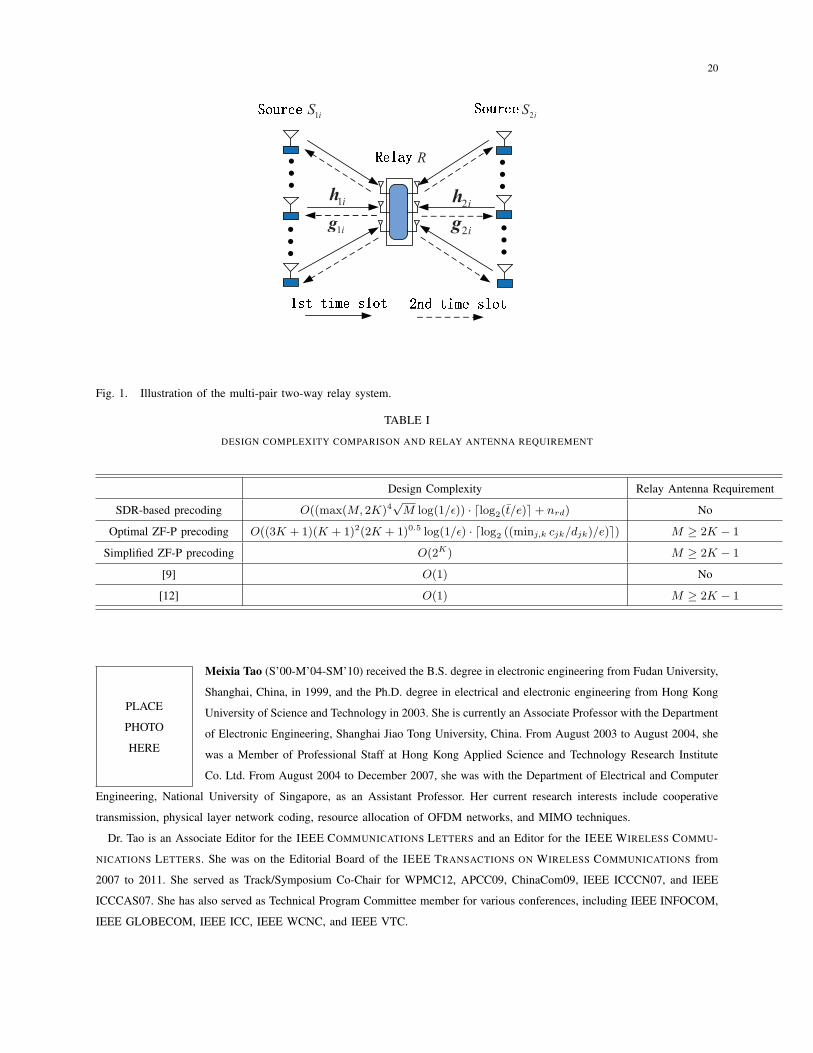
Consider a multi-pair two-way relay system as shown in Fig. 1, where multiple pairs of
source nodes intend to exchange information within each pair, denoted as S1k and S2k, for
k = 1, 2, · · · , K, under the assistance of a common relay node, denoted as R. Each source node
is equipped with single antenna while the relay node is equipped with M antennas. Due to the
impairments such as multipath fading, shadowing and path loss of wireless channels, we assume
that the direct-path link between the each source pair can be ignored. It is also supposed that the
relay node operates in the half-duplex mode, i.e., it cannot transmit and receive simultaneously.
The bi-directional transmission of all user pairs are completed in two time slots by applying
AF two-way relaying. In the first time slot, also referred to as multiple-access (MAC) phase, all
the 2K sources transmit their signals to the relay node simultaneously over the same frequency
band. Let sjk denote the signal transmitted from source Sjk with E(sjks∗jk) = Pjk where j = 1, 2
denotes the user index within each pair, and k = 1, 2, · · · , K denotes the pair index, Pjk is the
transmit power at source Sjk. The received signal at the relay node in the first time slot can be
expressed as
yR =K∑k=1
(h1ks1k + h2ks2k) + nR
= H1s1 +H2s2 + nR, (1)
where hjk ∈ CM×1 is the channel vector from Sjk to relay node R during the MAC phase,
Hj = [hj1,hj2, . . . ,hjK ] and sj = [sj1, sj2, . . . , sjK ]T . Here nR ∼ CN (0, σ2
RIM) denotes the
additive complex Gaussian noise vector at the relay node.
After receiving the signals transmitted from the sources, the relay node applies linear process-
ing by multiplying it with a precoding matrix F ∈ CM×M . Then the M × 1 signal vector to be
transmitted from the relay node can be expressed as
xR = FyR.
We assume that the maximum transmission power at the relay node is PR, which yields
Tr{F(H1P1PH1 H
H1 +H2P2P
H2 H
H2 + σ2
RIM)FH} ≤ PR, (2)

6
where Pj = Diag(√
Pj1,√Pj2, · · · ,
√PjK
), j = 1, 2. In the second time slot, also referred
to as broadcast (BC) phase, the relay node R broadcasts xR to all 2K user receivers. Then the
received signals at Sjk can be written as
yjk =K∑l=1
gTjkFhjlsjl +
K∑l=1
gTjkFhjlsjl + gT
jkFnR
+ njk, j = 1, 2, k = 1, 2, · · · , K
(3)
where j = 2 if j = 1 and j = 1 if j = 2, gjk ∈ CM×1 denotes the channel vector from the relay
node R to source Sjk and njk ∼ CN (0, σ2jk) denote the additive complex Gaussian noise at Sjk.
In the considered multi-pair two-way relay systems, we assume that the channel characteristics
of each link change slowly enough so that they can be perfectly estimated by using pilot symbols
or training sequences. Besides that, the relay precoding design is conducted at the relay node
due to its convenience to collect the channel state information (CSI). Moreover, we suppose
that each node Sjk estimates the combined channel coefficients gTjkFhjk and gT
jkFhjk by itself.
Since the node Sjk knows its own transmit signal sjk, the back-propagating self-interference
term gTjkFhjksjk can be completely canceled from yjk in (3) before the demodulation, which
yields
yjk =gTjkFhjksjk +
∑l =k
(gTjkFhjlsjl + gT
jkFhjlsjl)
+ gTjkFnR + njk,
(4)
for j = 1, 2 and k = 1, 2, · · · , K. In (4) the first term is the desired signal, the second term is
the interference from other pairs of users and the remaining terms represent the back-propagated
noise from the relay node and the additive noise at the destination itself.
From (4), the performance of each user (with single-user detection) can be directly character-
ized by the signal-to-interference-plus-noise ratio (SINR), which is written as
SINRjk =
Pjk|gTjkFhjk|2∑
l =k
(Pjl|gT
jkFhjl|2 + Pjl|gTjkFhjl|2
)+ σ2
R||gTjkF||22 + σ2
jk
.(5)
Accordingly, the achievable rate is expressed as γjk = 12log2 (1 + SINRjk) where the pre-log
factor 12
is due to the fact that two time slots are used for one round of information exchange. Our
objective is to maximize the minimum achievable rate among all the users, thereby, providing
7
max-min fairness. Note that considering user fairness is more relevant than sum-rate performance
in multi-pair two-way relay systems. The optimization problem is formulated as
maxF
min∀j∈{1,2}, k∈{1,2,...,K}
γjk (6)
s.t. (2)
It is easy to verify that the relay precoding design problem (6) is nonconvex. The optimal
solution is not easy to obtain in an efficient way. In Section III, we introduce the SDR based
precoding design which does not impose any constraints on the relay antenna number. Then in
Section IV, we introduce a precoding design with ZF structure, which has lower computational
complexity but requires certain constraints on the relay antenna number.
III. PRECODING DESIGN BASED ON SEMIDEFINITE PROGRAMMING RELAXATION
Since maximizing the minimum user rate is equivalent to maximizing the minimum user SINR,
the max-min problem in (6) can be equivalently written as:
maxF
min∀j,k
Tr(Pjkg
∗jkg
TjkFhjkh
HjkF
H)
Ejk + σ2RTr
(g∗jkg
TjkFF
H)+ σ2
jk
(7a)
s.t. (2) (7b)
where
Ejk = Tr
(g∗jkg
TjkF
(∑l =k
(PjlhjlhHjl + Pjlhjlh
Hjl )
)FH
).
In obtaining (7a), the rules |aTb|2 = Tr(a∗aTbbH) and ||aTB||22 = Tr(a∗aTBBH) have been
used for the SINR expression in (5). Notice that due to the fractional structure of the objective
function, (7) is similar to a quasi-convex problem according to [16, Chapter 4.2.5]. Hence we
can rewrite (7) as the following optimization problem by introducing an auxiliary variable t
maxF,t
t (8)
s.t.Tr(Pjkg
∗jkg
TjkFhjkh
HjkF
H)
Ejk + σ2RTr
(g∗jkg
TjkFF
H)+ σ2
jk
≥ t, ∀j, k
and (2)

8
Then, solving (8) can be simplified by using bisection search. More specifically, we first fix the
variable t as t (t should be chosen from the specific interval containing the optimal t), and then
solve the following problem
minF
Tr{F(H1P1PH1 H
H1 +H2P2P
H2 H
H2 + σ2
RIM)FH} (9a)
s.t.Tr(Pjkg
∗jkg
TjkFhjkh
HjkF
H)
Ejk + σ2RTr
(g∗jkg
TjkFF
H)+ σ2
jk
≥ t, ∀j, k (9b)
Problem (9) can be interpreted as minimizing the relay power consumption while guaranteeing
that the SINR of each user is above a pre-determined threshold. Since SINR is a monotonically
increasing function with respect to the relay power PR, if the optimal solution of (9) for a given
t is larger than PR, it means that the given minimum SINR threshold t cannot be attained by all
users in the system and hence should be reduced. Otherwise, if the optimal solution is smaller
than PR, we should increase t. As such, problem (9) can be regarded as a feasibility check
problem. Now, the optimal solution of (8) can be found if the optimal solution of subproblem
(9) is obtained in each iteration of the bisection search.
In the following, we recast (9) into a suitable form such that efficient optimization tools can
be applied to find its solution. To proceed, the SINR constraint (9b) is rewritten as
Tr
(Pjk
tg∗jkg
TjkFhjkh
HjkF
H
)− Tr
(g∗jkg
TjkFQjkF
H)≥ σ2
jk, (10)
where Qjk =∑
l =k
(Pjlhjlh
Hjl + Pjlhjlh
Hjl
)+ σ2
RIM . By using the rule [17]
Tr (ABCD) =(vec(DT )
)T (CT ⊗A
)vec(B), (11)
the inequality (10) can be reexpressed as
fH(R1
jk(t)−R2jk
)f ≥ σ2
jk, (12)
where f = vec (F), R1jk(t) =
Pjk
t
(hjkh
Hjk
)T⊗(g∗jkg
Tjk
)and R2
jk = QTjk⊗
(g∗jkg
Tjk
). Again using
(11), the objective function in (9a) can be equivalently denoted as
Tr{F(H1P1PH1 H
H1 +H2P2P
H2 H
H2 + σ2
RIM)FH} = fHRf , (13)
where R =(∑2
j=1HjPjPHj H
Hj + σ2
RIM
)T⊗ IM . According to (12) and (13), the optimization
problem (9) is transformed into the quadratically constrained quadratic program (QCQP) form

9
as
minf
fHRf (14)
s.t. fHRjk(t)f ≥ σ2jk,∀j, k
where Rjk(t) = R1jk(t) − R2
jk. By introducing F = f × fH ∈ CM2×M2 , we further transform
(14) into the following semidefinite programming (SDP) form:
minF≽0
Tr(RF)
(15)
s.t. Tr(Rjk(t)F
)≥ σ2
jk, ∀j, k,
Rank(F) = 1
Due to the rank-one constraint, the optimization problem (15) is nonconvex. So we relax the
rank-one constraint and solve the problem:
minF≽0
Tr(RF)
(16a)
s.t. Tr(Rjk(t)F
)≥ σ2
jk,∀j, k, (16b)
The optimal solution of (16) can be readily obtained due to its convexity.
After the termination of bisection search, if the obtained F, denoted as Fopt, in (16) is rank-
one, the optimal solution of (14), denoted as fopt, can be obtained by applying the eigenvalue
decomposition (EVD) technique, i.e.,
fopt =√du, (17)
where d and u are the eigenvalue and eigenvector of Fopt, respectively. Otherwise, we apply
the randomization technique [18] to obtain the final solution of (14) from (16). Namely, we
first generate a random vector x = (Fopt)1/2n with n ∼ CN (0, IM2) and set X = xxH . If X
satisfies Tr(Rjk(t)X
)> 0, ∀j, k, then one candidate of solution of (14) can be obtained as
x = ax, where the scalar a is chosen to minimize the power consumption while satisfying the
constraint in (16b). It can be seen easily that a = maxj,k
√σ2jk/Tr
(Rjk(t)X
). After generating
a number of samples, the best candidate which obtains the minimum relay power is chosen to
be the solution of (14). If the number of samples are large enough, the randomization technique
can find the optimal solution of (14) on average. To obtain the final solution of (7), we also
need to scale x to satisfy the relay power constraint.

10
Overall, the SDR based precoding design is summarized as:
Algorithm 1 (SDR-based relay precoding design)
• Find the upper bound of t as t and set tmin = 0, tmax = t,
• Repeat
1) Set t = (tmin + tmax)/2;
2) Solve (16) and denote the optimal relay precoder as Fopt(t);
3) Compute the consumed relay power P = Tr(RFopt(t)
). If P > PR, set tmax = t. Otherwise, set tmin = t;
• Until |tmax − tmin| ≤ e (where e is a preset error precision.)
• Obtain rank-one solution: If Fopt in (16) is rank-one, then obtain the optimal relay precoder of (14) by using EVD as
in (17). Otherwise, apply the randomization approach to get the final solution;
Remark 1: In Algorithm 1, the upper bound t can be obtained by ignoring the interference
from other users. More specifically, for each Sjk, we only consider the effective channel link gjk
and hjk. Then as shown in [19], the optimal relay precoder should have a form as Fjk = UΛVH
where U is the right singular-vector matrix of gjk and V is the left singular-vector matrix of hjk.
Since both hjk and gjk have only one positive singular value, the optimal Fjk can be written as
Fjk = αjkgjkhHjk, where αjk =
√PR
Pjk||gjk||22||hjk||42+σ2R||gjkh
Hjk
||2Fis used to scale the transmit signal
at relay node to satisfy the power constraint. Then we obtain an upper bound of t as
t = maxj,k
α2jk||gjk||42||hjk||42
α2jkσ
2R||gjk||42||hjk||22 + σ2
jk
.
Remark 2: The obtained t after the termination of bisection search and before extracting the
rank-one solution in Algorithm 1 can be viewed as an upper bound of the optimal solution of
the original problem (7). This is because relaxing the rank-one constraint enlarges the feasible
region of the optimized variable in (15). This upper bound can be used to validate the optimality
of the SDR-based precoding.
IV. PRECODING DESIGN BASED ON ZERO-FORCING
Although Algorithm 1 attains good performance as verified in Section VI, it usually results
in relative high computational complexity. In this section, we apply the zero-forcing structure in
the relay precoder design as in [11], [12], [14], [20] so that the precoding design for max-min
fairness reduces to a simple power allocation problem. This method may lead to a sub-optimal
solution, however, it has much lower computational complexity.

11
Generally, there are two ways to perform the zero-forcing precoding at the relay node. One
way is to use the zero-forcing precoding to eliminate all the interference, including the self-
interference, among the users as in [9]. The complete interference cancelation in such scheme
requires that the relay node has enough relay antennas (satisfying M ≥ 2K) to construct the null
space for each user. In this case, no self-interference cancelation is needed at each destination
receiver. The alternative way is to combine the techniques of relay zero-forcing and physical
layer network coding such that both the relay and the destination nodes participate to cancel the
interference. In this way, the relay precoder only needs to eliminate the inter-pair interference
but not the intra-pair interference (thus we refer to our proposed ZF based scheme as pair-wise
zero-forcing (ZF-P) relay precoding). For such ZF-P precoding scheme, the relay node needs at
least 2K − 1 antennas instead of 2K antennas as required in the first scheme. A similar ZF-
based precoding scheme is introduced in [12]. But that work does not study power optimization,
neither user fairness.
The main idea of the proposed ZF-P precoding is to adopt the block-diagonalization (BD)
technique to eliminate the inter-pair interference in both MAC and BC phases. The same idea
has also been used for the cellular based MU-TWRS in [14]. For ease of presentation, we set
the bidirectional transmission between S1k and S2k as example. We first define Hk as
Hk =[H1, H2, . . . , Hk−1, Hk+1, . . . , HK
], (18)
where Hk = [h1k,h2k] is the channel matrix of the k-th pair in MAC phase. Applying the
singular-value decomposition (SVD) technique to (18), we get
Hk =[U
(1)
Hk,U
(0)
Hk
]ΣHk
VHHk
,
where U(1)
Hk∈ CM×(2K−2) holds the first 2K − 2 left singular vectors, U(0)
Hk∈ CM×(M−2K+2)
holds the last M − 2K + 2 left singular vectors which forms the null space of HHk . To obtain
the receive beamforming vector, we further define[u(1)hk,U
(0)hk
]Σhk
VHhk
= U(0)
Hk
Hhk, (19)
where hk = h1k + h2k, u(1)hk
∈ C(M−2K+2)×1 and U(0)hk
∈ C(M−2K+2)×(M−2K+1) form the
orthogonal basis of hHk U
(0)
H1kand its null space, respectively. Therefore, applying the receive
beamforming vector as
tmk = U(0)
Hku(1)h1k
, (20)

12
we can get zero inter-pair interference at the relay node for pair {S1k, S2k} within the MAC
phase. Similarly, we can also design the transmit beamforming vector for S1k and S2k in the BC
phase by defining
Gk =[G1, G2, . . . , Gk−1, Gk+1, . . . , GK
]T=UGk
ΣGk
[V
(1)
Gk,V
(0)
Gk
]H,
(21)
where Gk = [g1k,g2k] denotes the channel matrix of the k-th pair in BC phase, and V(0)
Gk∈
CM×(M−2K+2) denotes the null basis of Gk. Then we get
UgkΣgk
[v(1)gk,V(0)
gk
]H= gT
kV(0)
Gk, (22)
where gk = g1k+g2k, v(1)gk and V
(0)gk are defined similarly as in (19). The inter-pair interference-
free transmit beamforming vector for S1k and S2k within the BC phase is obtained as tbk =
V(0)
Gkv(1)gk . Finally, we get the relay precoder which has following structure
T =K∑k=1
δktbkt
mk
H = Tb∆THm. (23)
where Tb =[tb1, t
b2, · · · , tbK
], Tm = [tm1 , t
m2 , · · · , tmK ] and ∆ = Diag (δ1, δ2, · · · , δK) with δk,
∀k being the power allocation parameter for pair {S1k, S2k}. By using the relay precoder (23),
the inter-pair interference for all other users is completely canceled and the received signal at
each node can be denoted as
yjk =δkgTjkt
bkt
mk
Hhjksjk + δkgTjkt
bkt
mk
Hhjksjk
+ δkgTjkt
bkt
mk
HnR + njk, ∀j, k(24)
where the first term is the desired signal, the second term is the self interference and the remaining
terms represent the back-propagated noise from the relay node and the additive noise at the
destination itself. Then after the self-interference cancelation in each node, the received signal-
to-noise ratio (SNR) is written as
SNRjk =δ2kcjk
δ2kdjk + σ2jk
, ∀j, k (25)
where cjk = Pjk|gTjkt
bkt
mk
Hhjk|2, djk = σ2R||gT
jktbkt
mk
H ||22.

13
By introducing a power allocation vector δ = [δ1, δ2, · · · , δK ]T , the original max-min problem
expressed in (7) can be rewritten as the following power allocation problem
maxδ,t
t (26a)
s.t.δ2kcjk
δ2kdjk + σ2jk
≥ t,∀j, k
δT(K⊙ LT
)δ ≤ PR (26b)
where K = THb Tb and L = TH
m(∑2
j=1HjPjPHj H
Hj + σ2
RIM)Tm. Here the constraint (26b) is
obtained by using the rule Tr(AMBTM) = mT (A⊙B)m with M = Diag(m) in [17] for the
relay power constraint (2). Since both K and L are positive semidefinite, the matrix K⊙LT is
also positive semidefinite [17]. Thus, the relay power constraint in (26b) is convex. Similar to
Algorithm 1, we can solve (26) by converting it into a series of subproblems as follows for a
fixed t:
minδ
δT(K⊙ LT
)δ (27)
s.t. δk ≥√(
σ2jk t)/(cjk − djk t
), ∀j, k
where the optimal t can be obtained using bisection search. Note that, during the bisection
search, the maximum value of t should be chosen such that cjk − djk t > 0 for ∀j, k. Therefore,
the search region of t is easy to be determined as [0, t] where t = minj,k cjk/djk.
Although the bisection approach can obtain the optimal power allocation, it still leads to
high computational complexity. By taking a closer look at problem (26), we find that the main
difficulty in solving (26) is due to the fact that the matrix K ⊙ LT is non-diagonal. Thus, we
next propose a simplified power allocation algorithm by relaxing the matrix L as a diagonal
matrix L which is given as
L = σ2RD+TH
m(H1P1PH1 H
H1 +H2P2P
H2 H
H2 )Tm. (28)
Here D is a diagonal matrix containing the diagonal entries of THmTm. The second term in the
right hand side of (28) is diagonal because each column vector tmk as defined in (20) lies in
the null space of HHk defined in (18) and as a result, the matrix TH
m diagonalizes H1 and H2
simultaneously.
14
Substituting L into (26), we get the following simplified problem
maxt,δk,∀k
t (29)
s.t.δ2kcjk
δ2kdjk + σ2jk
≥ t, ∀j, k∑k
βkδ2k ≤ PR
where βk is the diagonal entry of K⊙ L. Note that the introduced relaxation can be ignored if
SNR in the MAC phase is large enough. To solve (29), we have the following lemma.
Lemma 1: For the optimal solution of (29), it has
min
{δ2kc1k
δ2kd1k + σ21k
,δ2kc2k
δ2kd2k + σ22k
}= t, ∀k (30)
and ∑k
βkδ2k = PR.
Proof: It is easy to verify that SNRjk in (25) is an increasing function with respect to δk.
Thus, we conclude that the optimal solution in (29) must consume all the power at the relay node,
i.e.,∑
k βkδ2k = PR. If at the optimal solution, the minimum SNR of the pair {S1k, S2k} is larger
than the minimum SNR of the pair {S1l, S2l} when l = k, we can always decrease the value δk
and increase the value δl to further increase minj,k SNRjk. This contradicts the assumption that
{δk} is the optimal solution. Thus, we conclude that the optimal power allocation in (29) should
make the minimum SNR within all the user pairs equal to each other.
Applying Lemma 1, we obtain the following simplified method to conduct the power alloca-
tion. Namely, we first assume that for pair {S1k, S2k}, node Sjkk has the minimum SNR where
jk can be chosen as 1 or 2. Then based on Lemma 1, we have
δ2k =σ2jkk
cjkk/t− djkk, k = 1, 2, · · · , K. (31)
Substituting (31) into the power constraint, we obtain∑k
βkσ2jkk
cjkk/t− djkk= PR. (32)
Then we can solve (32) to get the value of t for the chosen {j1, j2, · · · , jK}. By trying all the
possible cases of {j1, j2, · · · , jK}, the maximum t is finally obtained as the optimal solution
of (29) and the optimal power allocation can be further acquired through (31). If K is not

15
very large, the computational complexity can be significantly reduced by using the proposed
simplified method. The design complexity of different precoding schemes shall be compared in
the next section. Besides that, we also find that compared to the method of solving (26) using
bisection search, no advanced software is needed to solve (29) by using Lemma 1.
Note that the solution obtained from Lemma 1 is based on relaxation in (28). The derived
solution may violate the relay power constraint or do not consume all the relay power. Thus we
need to scale the obtained relay precoder to satisfy the power constraint or to further improve
the performance. The scalar can be computed as
θ =
√PR
Tr(T(H1P1PH1 H
H1 +H2P2PH
2 HH2 + σ2
RIM)TH),
where T = Tb∆THm with ∆ being solved from (29). Finally, we obtain the relay precoder as
F = θT.
V. DISCUSSION ON COMPLEXITY AND ANTENNA REQUIREMENT
In this section, we shall provide discussions on the design complexity and the relay antenna
requirement for the proposed precoding designs and the existing methods in [9] and [12]. The
overall comparisons are summarized in Table I, where “Optimal ZF-P precoding” means that
the optimal power allocation method is applied and “Simplified ZF-P precoding” means to use
the simplified relay power allocation method. In addition, since the designs proposed in [9] and
[12] have the closed-form solutions, their complexities can also be simply viewed as O(1).
According to [18], the complexity of solving the SDP problem (16) can be approximated as
O(max(M, 2K)4√M log(1/ϵ)), where ϵ denotes the solution accuracy. The number of iterations
for the bisection search used in Algorithm 1 is given by ⌈log2(t/e)⌉ where t and e are the
preset search bound and error precision, respectively. Therefore, the overall complexity of the
SDR based precoding design is as shown in Table I, where nrd denotes the complexity of
randomization.
For optimal ZF-P precoding, since the QCQP problem (27) can be transformed into the
second-order cone programming (SOCP) problem, according to [21], its complexity can be
approximated as O((3K + 1)(K + 1)2(2K + 1)0.5 ln(1/ϵ)). Since the number of iteration is
⌈log2 ((minj,k cjk/djk)/e)⌉, the overall complexity of the optimal ZF-P precoding is as shown in
Table I. For simplified ZF-P precoding, since we only need to solve the equation (32) for each

16
chosen {j1, j2, · · · , jK}, the design complexity can be simply viewed as O(2K). We can find
that if K is not very large, the simplified ZF-P precoding can save the computational complexity
significantly. While in practice, the number of user pair K cannot be very large in order to
achieve effective transmission.
For the required relay antenna number, since the proposed ZF-P precoding design and [12]
apply the block-diagonalization technique, they need at least 2K − 1 relay antennas. While for
the proposed SDR precoding design and [9], there is no constraint imposed on the relay antenna
number.
VI. SIMULATION RESULTS
In this section, some examples are presented to evaluate the proposed precoding designs.
The channel on each link is set to be normalized Rayleigh fading, i.e., the elements of each
channel matrix are complex Gaussian random variables with zero mean and unit variance. We
also assume Pjk = P and σ2jk = σ2 for ∀j, k. The average SNR for the MAC and BC phases
are defined as ρMAC = KPσ2R
and ρBC = PR
σ2 , respectively.
In Fig. 2(a) and 2(b), we check the optimality of the proposed SDR based precoding design
for K = 2 user pairs and K = 3 user pairs, respectively, by comparing with the performance
upper bound. The upper bound is obtained by skipping the procedure to get the rank-one solution
as claimed in Remark 2. It is observed that the proposed SDR based precoding design almost
attains the performance upper bound, which confirms that the solution obtained from the SDR
based method approaches the optimal solution. On the other hand, we find that the SDR based
precoding design works well for any number of relay antennas. The observation also shows that
the performance of SDR based precoding design is sensitive to the relay antenna number and it
can be enhanced significantly if the relay antenna number is increased.
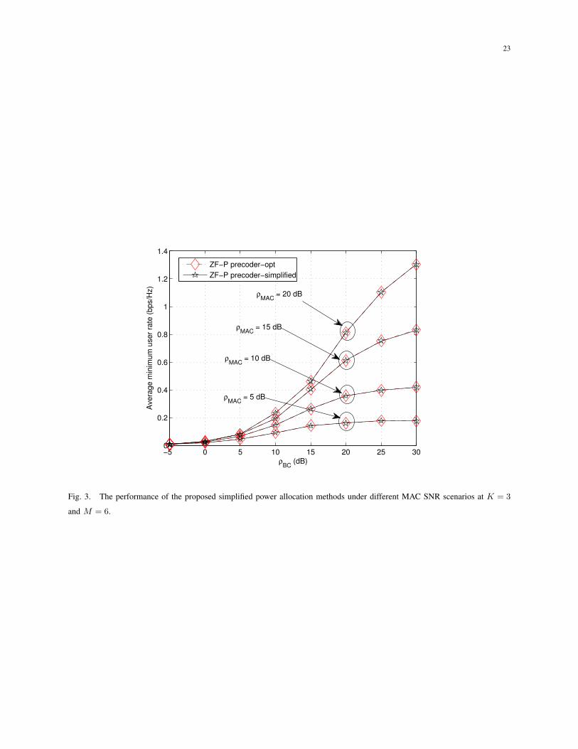
Fig. 3 shows the optimality of the solution obtained by the proposed simplified power allocation
method for the ZF-P precoding design. Although we have claimed that the applied relaxation can
only be ignored under the high MAC SNR conditions, the observations verify that the proposed
simplified power allocation method by Lemma 1 also works well in the low SNR scenarios. Thus,
without loss of generality, we next only use the simplified method for performance comparison.
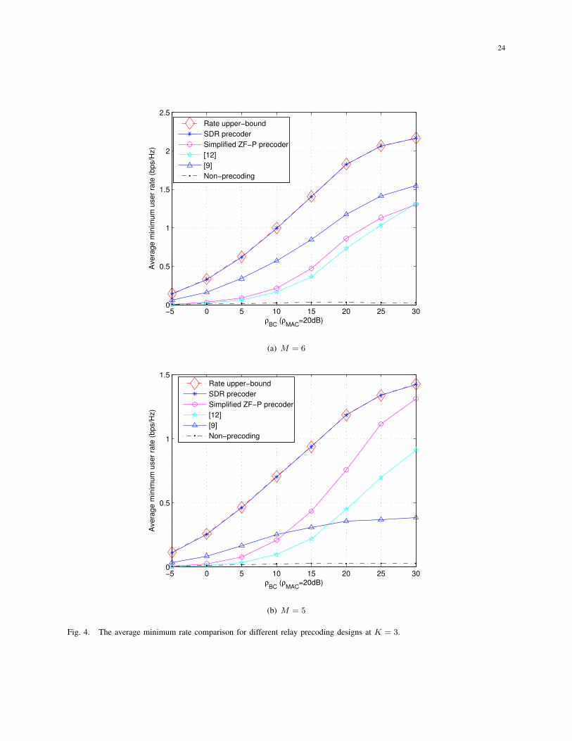
In Fig. 4(a) and Fig. 4(b), we compare the proposed designs with the existing methods in
[9] with MMSE design and in [12] with coherent combining of null-space vectors scheme in

17
terms of minimum user rate. Here we consider K = 3 user pairs with M = 5, 6 antennas at
the relay node. We observe that the SDR based precoding design significantly outperforms the
methods in [9], [12] for both M = 5 and M = 6. For the simplified ZF-P precoding scheme,
one can see that, at M = 6, it performs slightly better than [12] and performs worse than the
methods in [9]. This indicates that if the number of relay antennas is large enough, using the
relay precoder to completely eliminate the interference among all the users is more beneficial
than the scheme with network coding to achieve the user fairness. However, when with less relay
antennas, as shown in Fig. 4(b) where we set M = 5, the performance of [9] is significantly
degraded and becomes worse than the simplified ZF-P precoding scheme when ρBC is lager than
10 dB. Compared with [12], the proposed ZF-P is consistently better.
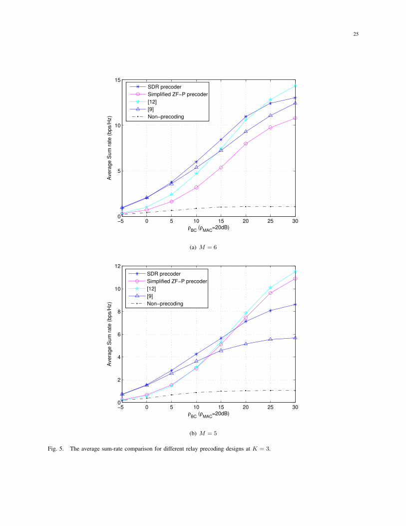
Besides the max-min fairness, we also present the sum-rate performance of the proposed
designs in comparison with existing designs in Fig. 5(a) and 5(b). We observe that the SDR
based precoding design not only performs well to achieve the user fairness, it can also obtain
good performance in sum rate. Since the objective of the simplified ZF-P precoding design is to
achieve the user fairness, it suffers gain loss in the sum rate when M = 6. However, when with
less relay antennas, i.e., M = 5, the sum rate difference between [12] and the simplified ZF-P
precoding design is significantly reduced and the simplified ZF-P precoding design significantly
outperforms [9] when ρBC ≥ 10 dB.
In Fig. 6, we further illustrate the system outage performance achieved by the proposed designs
for K = 3. Since the considered system is a multiuser system, we define that the system is in
outage if any of the users is in outage. The target transmission rate of each user is set to be
R = 0.5 bits/s/Hz. In Fig. 6, we can observe similar results as in Fig. 4. Namely, the SDR
based precoding always performs the best. Although the simplified ZF-P precoding is inferior
to [9] when M = 6, it begins to significantly outperform [9] when with less relay antennas at
M = 5. The curves in Fig. 6 also show that in general, the SDR based precoding obtains the
highest diversity order among all the considered schemes and that the simplified ZF-P precoding
almost achieves the same diversity order with [12]. When M = 6, [9] can achieve higher diversity
order than the simplified ZF-P precoding. However, when with less relay antennas, the achievable
diversity order of [9] is greatly reduced as shown in Fig. 6(b).
Based on these observations, we conclude that the proposed SDR based precoding can obtain
the best performance in both minimum user rate and system outage among all the considered

18
schemes. It also achieves good system sum-rate performance at any number of relay antennas.
Although from Table I, we see that the SDR based precoding has the highest design complexity,
its performance gain in both minimum user rate and system outage over the existing works is also
dramatic. We believe that such performance gain is worthwhile in certain scenarios where the
processing ability is not a limiting issue. When the number of relay antennas is just enough, the
proposed simplified ZF-P precoding method can provide a good balance between performance
and complexity.
VII. CONCLUSIONS
In this paper, we investigated the linear relay precoding to achieve the max-min user fairness
for multi-pair two-way MIMO relay systems. By using the bisection search, we first proposed to
convert the primal precoding design into a series of SDP optimization problems and then obtained
the final solution using semidefinite relaxation. This SDR-based precoding can achieve good
performance and is suitable for any number of relay antennas. Simulation results demonstrated
that it achieves significantly higher minimum user rate than existing precoding schemes while
maintaining reasonable sum-rate performance. We further proposed the ZF-based relay precoding
structure to eliminate inter-pair interference. The precoder optimization then reduces to a power
allocation problem. We solved the optimal power allocation through standard optimization tools.
Moreover, we presented a simplified power allocation method without performance degrada-
tion. Simulation results showed that this pair-wise ZF precoding scheme with simplified power
allocation is promising when the number of relay antennas is just enough.
REFERENCES
[1] R. Ahlswede, N. Cai, S.-Y. R. Li, and R. W. Yeung, “Network information flow,” IEEE Trans. Inf. Theory, vol. 46, no. 4,
pp. 1204–1216, 2000.
[2] S. Zhang, S. C. Liew, and L. L. Lam, “Physical layer network coding,” in ACM SIGCOM’06, Sept. 2006.
[3] B. Rankov and A. Wittneben, “Spectral efficient protocols for half-duplex fading relay channels,” IEEE J. Sel. Areas
Commun., vol. 25, no. 2, pp. 379–389, 2007.
[4] S. Katti, H. Rahul, W. Hu, D. Katabi, M. Medard, and J. Crowcroft, “Xors in the air: Practical wireless network coding,”
IEEE/ACM Trans. Netw., vol. 16, no. 3, pp. 497–510, 2008.
[5] M. Chen and A. Yener, “Multiuser two-way relaying: detection and interference management strategies,” Wireless
Communication, IEEE Trans. on, vol. 8, no. 8, pp. 4296–4305, 2009.
[6] K. Jitvanichphaibool, R. Zhang, and Y.-C. Liang, “Optimal resource allocation for two-way relay-assisted OFDMA,” IEEE
Trans. Veh. Technol., vol. 58, no. 7, pp. 3311–3321, 2009.
19
[7] C. Esli and A. Wittneben, “One- and two-way decode-and-forward relaying for wireless multiuser MIMO networks,” in
Proc. IEEE Global Telecommunications Conf. IEEE GLOBECOM 2008, 2008, pp. 1–6.
[8] ——, “Multiuser MIMO two-way relaying for cellular communications,” in Proc. IEEE 19th Int. Symp. Personal, Indoor
and Mobile Radio Communications PIMRC 2008, 2008, pp. 1–6.
[9] J. Joung and A. H. Sayed, “Multiuser two-way amplify-and-forward relay processing and power control methods for
beamforming systems,” IEEE Trans. Signal Process., vol. 58, no. 3, pp. 1833–1846, 2010.
[10] ——, “User selection methods for multiuser two-way relay communications using space division multiple access,” IEEE
Trans. Wireless Commun., vol. 9, no. 7, pp. 2130–2136, 2010.
[11] E. Yilmaz, R. Zakhour, D. Gesbert, and R. Knopp, “Multi-pair two-way relay channel with multiple antenna relay station,”
in Proc. IEEE Int Communications (ICC) Conf, 2010.
[12] C. Y. Leow, Z. Ding, K. K. Leung, and D. L. Goeckel, “On the study of analogue network coding for multi-pair, bidirectional
relay channels,” IEEE Trans. Wireless Commun., vol. 10, no. 2, pp. 670–681, 2011.
[13] Z. Ding, I. Krikidis, J. Thompson, and K. K. Leung, “Physical layer network coding and precoding for the two-way relay
channel in cellular systems,” IEEE Trans. Signal Process., vol. 59, no. 2, pp. 696–712, 2011.
[14] J. Zhang, F. Roemer, and M. Haardt, “Beamforming design for multi-user two-way relaying with MIMO amplify and
forward relays,” in Proc. IEEE Int Acoustics, Speech and Signal Processing (ICASSP) Conf, 2011, pp. 2824–2827.
[15] F. Roemer and M. Haardt, “Algebraic norm-maximizing (anomax) transmit strategy for two-way relaying with MIMO
amplify and forward relays,” IEEE Signal Process. Lett., vol. 16, no. 10, pp. 909–912, 2009.
[16] S. Boyd and L. Vandenberghe, Convex Optimization. Cambridge University Press, 2004.
[17] X. Zhang, Matrix analysis and applications. China, Tsinghua University Press, 2004.
[18] Z.-Q. Luo, W. kin Ma, A. M.-C. So, Y. Ye, and S. Zhang, “Semidefinite relaxation of quadratic optimization problems,”
IEEE Signal Process. Mag., vol. 27, no. 3, pp. 20–34, 2010.
[19] X. Tang and Y. Hua, “Optimal design of non-regenerative MIMO wireless relays,” IEEE Trans. Wireless Commun., vol. 6,
no. 4, pp. 1398–1407, 2007.
[20] F. Roemer, J. Zhang, M. Haardt, and E. Jorswieck, “Spectrum and infrastructure sharing in wireless networks: A case
study with relay-assisted communication,” in Future Network and MobileSummit 2010 Conference Proceedings. IIMC
International Information Management Corporation, 2010.
[21] M. Lobo, L. Vandenberghe, S. Boyd, and H. Lebret, “Applications of second-order cone programming,” Linear Algebra
and its Applications, vol. 284, pp. 193–228, 1998.
20
1iS
2iS
R
1ih
2ih
1ig
2ig
Fig. 1. Illustration of the multi-pair two-way relay system.
TABLE I
DESIGN COMPLEXITY COMPARISON AND RELAY ANTENNA REQUIREMENT
Design Complexity Relay Antenna Requirement
SDR-based precoding O((max(M, 2K)4√M log(1/ϵ)) · ⌈log2(t/e)⌉+ nrd) No
Optimal ZF-P precoding O((3K + 1)(K + 1)2(2K + 1)0.5 log(1/ϵ) · ⌈log2 ((minj,k cjk/djk)/e)⌉) M ≥ 2K − 1
Simplified ZF-P precoding O(2K) M ≥ 2K − 1
[9] O(1) No
[12] O(1) M ≥ 2K − 1
PLACE
PHOTO
HERE
Meixia Tao (S’00-M’04-SM’10) received the B.S. degree in electronic engineering from Fudan University,
Shanghai, China, in 1999, and the Ph.D. degree in electrical and electronic engineering from Hong Kong
University of Science and Technology in 2003. She is currently an Associate Professor with the Department
of Electronic Engineering, Shanghai Jiao Tong University, China. From August 2003 to August 2004, she
was a Member of Professional Staff at Hong Kong Applied Science and Technology Research Institute
Co. Ltd. From August 2004 to December 2007, she was with the Department of Electrical and Computer
Engineering, National University of Singapore, as an Assistant Professor. Her current research interests include cooperative
transmission, physical layer network coding, resource allocation of OFDM networks, and MIMO techniques.
Dr. Tao is an Associate Editor for the IEEE COMMUNICATIONS LETTERS and an Editor for the IEEE WIRELESS COMMU-
NICATIONS LETTERS. She was on the Editorial Board of the IEEE TRANSACTIONS ON WIRELESS COMMUNICATIONS from
2007 to 2011. She served as Track/Symposium Co-Chair for WPMC12, APCC09, ChinaCom09, IEEE ICCCN07, and IEEE
ICCCAS07. She has also served as Technical Program Committee member for various conferences, including IEEE INFOCOM,
IEEE GLOBECOM, IEEE ICC, IEEE WCNC, and IEEE VTC.

21
Dr. Tao is the recipient of the IEEE ComSoC Asia-Pacific Outstanding Young Researcher Award in 2009.
PLACE
PHOTO
HERE
Rui Wang received the B.S. degree from Anhui Normal University, Wuhu, China, in 2006, and the M.S.
degree from Shanghai University, Shanghai, China, in 2009 both in electronic engineering.
Currently he is pursuing his Ph.D. degree at the Institute of Wireless Communication Technology
(IWCT) in Shanghai Jiao Tong University. His research interests include digital image processing, cognitive
radio and signal processing for wireless cooperative communication.

22
−5 0 5 10 15 20 25 300
0.5
1
1.5
2
2.5
3
ρBC
(dB) (ρMAC
=20 dB)
Avera
ge m
inim
um
user
rate
(bps/H
z)
Upper−bound
SDRM = 4
M = 3
M = 2
(a) K = 2
−5 0 5 10 15 20 25 300
0.5
1
1.5
2
2.5
ρBC
(dB) (ρMAC
=20 dB)
Avera
ge m
inim
um
user
rate
(bps/H
z)
Upper−bound
SDR M = 6
M = 5
M = 4
M = 3
M = 2
(b) K = 3
Fig. 2. The performance of the proposed SDR-based precoding design at different relay antenna number for ρBC at ρMAC =
20dB.
23
−5 0 5 10 15 20 25 300
0.2
0.4
0.6
0.8
1
1.2
1.4
Avera
ge m
inim
um
user
rate
(bps/H
z)
ρBC
(dB)
ZF−P precoder−opt
ZF−P precoder−simplified
ρMAC
= 20 dB
ρMAC
= 15 dB
ρMAC
= 10 dB
ρMAC
= 5 dB
Fig. 3. The performance of the proposed simplified power allocation methods under different MAC SNR scenarios at K = 3
and M = 6.
24
−5 0 5 10 15 20 25 300
0.5
1
1.5
2
2.5
ρBC
(ρMAC
=20dB)
Avera
ge m
inim
um
user
rate
(bps/H
z)
Rate upper−bound
SDR precoder
Simplified ZF−P precoder
[12]
[9]
Non−precoding
(a) M = 6
−5 0 5 10 15 20 25 300
0.5
1
1.5
ρBC
(ρMAC
=20dB)
Avera
ge m
inim
um
user
rate
(bps/H
z)
Rate upper−bound
SDR precoder
Simplified ZF−P precoder
[12]
[9]
Non−precoding
(b) M = 5
Fig. 4. The average minimum rate comparison for different relay precoding designs at K = 3.
25
−5 0 5 10 15 20 25 300
5
10
15
ρBC
(ρMAC
=20dB)
Avera
ge S
um
rate
(bps/H
z)
SDR precoder
Simplified ZF−P precoder
[12]
[9]
Non−precoding
(a) M = 6
−5 0 5 10 15 20 25 300
2
4
6
8
10
12
ρBC
(ρMAC
=20dB)
Avera
ge S
um
rate
(bps/H
z)
SDR precoder
Simplified ZF−P precoder
[12]
[9]
Non−precoding
(b) M = 5
Fig. 5. The average sum-rate comparison for different relay precoding designs at K = 3.

26
−5 0 5 10 15 20 25 3010
−3
10−2
10−1
100
ρBC
(ρMAC
=20dB)
Outa
ge P
robabili
ty
SDR precoder
Simplified ZF−P precoder
[12]
[9]
(a) M = 6
−5 0 5 10 15 20 25 3010
−2
10−1
100
ρBC
(ρMAC
=20dB)
Outa
ge P
robabili
ty
SDR precoder
Simplified ZF−P precoder
[12]
[9]
(b) M = 5
Fig. 6. The outage performance comparison for different relay precoding designs with K = 3 at target user rate R = 0.5
bits/s/Hz.


![[EURASIP 2013] Linear Precoding in Distributed MIMO Systems With Partial CSIT](https://static.fdocuments.us/doc/165x107/577cd2281a28ab9e78953348/eurasip-2013-linear-precoding-in-distributed-mimo-systems-with-partial-csit.jpg)
![MIMO Wireless Linear Precoding - Tufts Universitymaivu/papers/SPM_MIMO_Wireless_Precoding.pdf[Using CSIT to improve link performance] [Mai Vu and Arogyaswami Paulraj] MIMO Wireless](https://static.fdocuments.us/doc/165x107/5aaa561a7f8b9a95188df246/mimo-wireless-linear-precoding-tufts-maivupapersspmmimowirelessprecodingpdfusing.jpg)

![Robust Precoding in Massive MIMO: A Deep Learning Approach · arXiv:2005.13134v1 [cs.IT] 27 May 2020 1 Robust Precoding in Massive MIMO: A Deep Learning Approach Junchao Shi, Student](https://static.fdocuments.us/doc/165x107/60d4a903db6c4b278a582b08/robust-precoding-in-massive-mimo-a-deep-learning-approach-arxiv200513134v1-csit.jpg)