
1. KOGA Project Concept - · 1. KOGA Project Concept 2. ... Wind, Temp., Air pressure Water Temp.,...
17
Transcript of 1. KOGA Project Concept - · 1. KOGA Project Concept 2. ... Wind, Temp., Air pressure Water Temp.,...

1. KOGA Project Concept
2. KOGA System Location
3. KOGA System Hardware
4. KOGA System Installation
5. Participate in PP-WET (Movie)
2
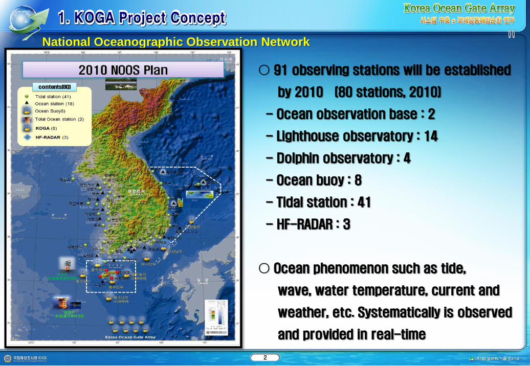
○ 91 observing stations will be established
by 2010 (80 stations, 2010)
- Ocean observation base : 2
- Lighthouse observatory : 14
- Dolphin observatory : 4
- Ocean buoy : 8
- Tidal station : 41
- HF-RADAR : 3
○ Ocean phenomenon such as tide,
wave, water temperature, current and
weather, etc. Systematically is observed
and provided in real-time
National Oceanographic Observation Network
3

4
Maritime
shippingTyphoon
Ocean
EnergyTsunami
Climate
Change
Numerical
Model
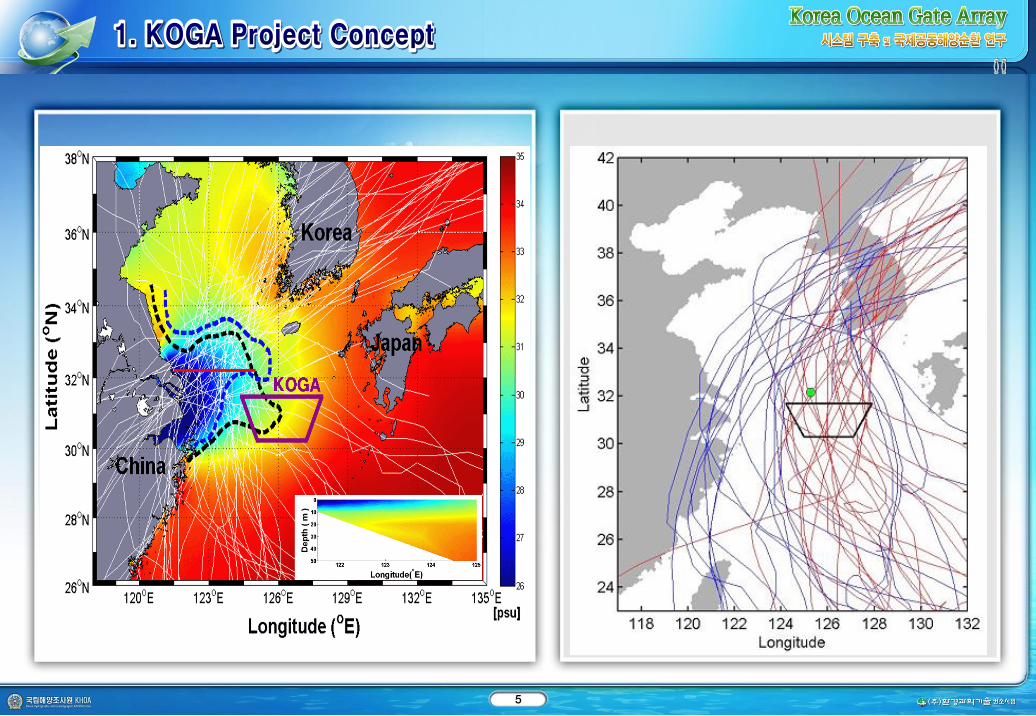
Main path of the typhoon affecting Korea
The branching area of the Tsushima Current from Kuroshio Current
Sea of detectable Earthquake occurred along Ryukyu Trench
Boundary Condition area of oceanography and meteorology Numerical Modeling
Entering Gateway of ship out to the Ocean
5

6
Installation Area of KOGA
Site Lat. Long Depth(m) Sediment Slope
koga06 32-00-04.115 127-02-40.528 118 sM Gentle
koga07 31-27-47.600 126-57-53.195 106 M Gentle
koga05 31-27-47.600 126-10-14.762 75 sM Gentle
koga01 31-27-47.600 125-01-49.757 55 sM Gentle
koga04 30-59-14.518 126-49-33.178 97 sM Gentle
koga08 30-59-14.518 126-09-10.731 86 sM Gentle
koga02 30-59-14.518 125-28-15.101 63 M Gentle
koga03 30-19-49.682 126-12-07.460 83 sM Gentle

7
KOGA_scripps
Wind, Temp., Air pressure
Water Temp., pressure, current,
Wave
Iridium(Satellite communication)
Remote Control Sys.(Data Communication:
two-way Iridium)
Acoustic Telemetry
KOGA_buoyWind direction, Wind speed, Temp., Air
pressure
Water Temp., Conductivity, Wave height,
Wave direction, Wave period
CO2, Hydrophone
KOGA_bottom(Trawl
Resistant Bottom
Mount)
Current profiler, Conductivity,
Water Temp., Tide, Wave..
8
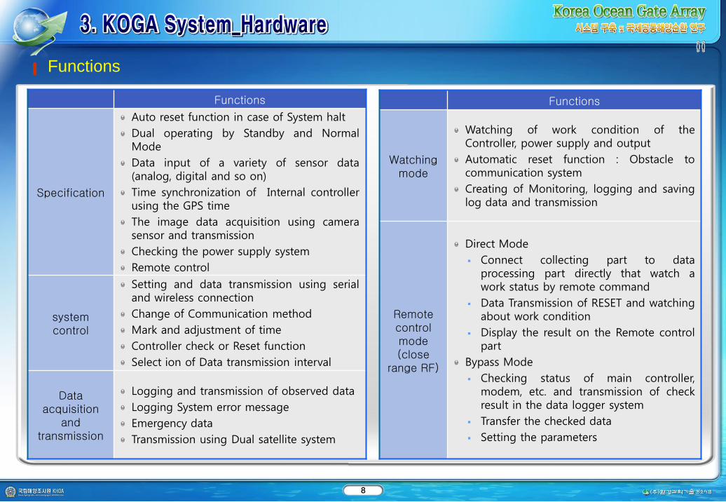
Functions
Functions
Specification
Auto reset function in case of System halt
Dual operating by Standby and NormalMode
Data input of a variety of sensor data(analog, digital and so on)
Time synchronization of Internal controllerusing the GPS time
The image data acquisition using camerasensor and transmission
Checking the power supply system
Remote control
system control
Setting and data transmission using serialand wireless connection
Change of Communication method
Mark and adjustment of time
Controller check or Reset function
Select ion of Data transmission interval
Data acquisition
and transmission
Logging and transmission of observed data
Logging System error message
Emergency data
Transmission using Dual satellite system
Functions
Watching mode
Watching of work condition of theController, power supply and output
Automatic reset function : Obstacle tocommunication system
Creating of Monitoring, logging and savinglog data and transmission
Remote control mode(close
range RF)
Direct Mode
Connect collecting part to dataprocessing part directly that watch awork status by remote command
Data Transmission of RESET and watchingabout work condition
Display the result on the Remote controlpart
Bypass Mode
Checking status of main controller,modem, etc. and transmission of checkresult in the data logger system
Transfer the checked data
Setting the parameters

9
KOGA Hardware Configuration
KOGA_Buoy configuration
KOGA_bottom(Underwater System)
KOGA_Buoy(Oversized)
Sensor
dome
Buoy
Hull Co 2 Equibrator
CT Sensor
Hippy
MOSE
ADCP
Underwater USN
Pop-Up
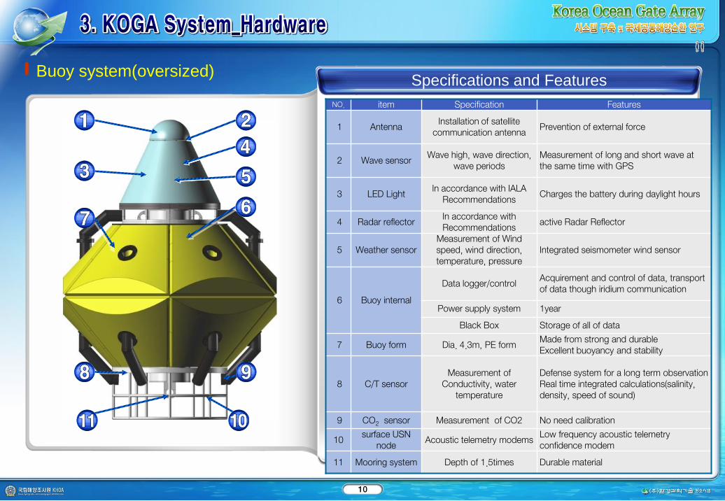
10
NO. item Specification Features
1 AntennaInstallation of satellite
communication antennaPrevention of external force
2 Wave sensorWave high, wave direction,
wave periodsMeasurement of long and short wave at the same time with GPS
3 LED LightIn accordance with IALA
Recommendations Charges the battery during daylight hours
4 Radar reflectorIn accordance with Recommendations
active Radar Reflector
5 Weather sensorMeasurement of Wind speed, wind direction, temperature, pressure
Integrated seismometer wind sensor
6 Buoy internal
Data logger/controlAcquirement and control of data, transport of data though iridium communication
Power supply system 1year
Black Box Storage of all of data
7 Buoy form Dia. 4.3m, PE formMade from strong and durableExcellent buoyancy and stability
8 C/T sensorMeasurement of
Conductivity, water temperature
Defense system for a long term observationReal time integrated calculations(salinity, density, speed of sound)
9 CO2 sensor Measurement of CO2 No need calibration
10surface USN
nodeAcoustic telemetry modems
Low frequency acoustic telemetry confidence modem
11 Mooring system Depth of 1.5times Durable material
Buoy system(oversized)Specifications and Features

11
Underwater systemSpecification sand Features
NO. Item Specification Features
1Emergency
TransponderUnderwater acoustic
transponder
To accommodate more batteries, and functions identicallyProviding three times the operational life
2Under water USN
nodeAcoustic telemetry
modemsLow frequency acoustic telemetry confidence modem
3Acoustic Doppler
current profiler(ADCP, RDCP)
Measurement of the water direction, water
speed, pressure, conductivity and
temperature for each layers
Broadband signal processing deliversvery low-noise data, resulting in unparalleleddata resolution and minimalpower consumption
4Submersible
Argos BeaconSatellite tracking and
alerting system
Transmit the signal through satellite communicationTo minimize corrosion never mount the pressure case to metal.
5Pop up Buoy
& A.R. Integration system
Underwater acoustic release system
Integrated marking buoy and A.R. system
6 TRBMTrawl resistant bottom
mountsWith Gimbals for ADCP, RDCP
7 Buoyancy form High density buoyancyHigh density buoyancy form for recovering TRBM
8 A.R. SystemAcoustic Releasing
system Released between TRBM and anchor by acoustic signal
9External
Battery PackPower supply system High performance battery (Low electric
discharge rate)

12
Buoy system(small)Specifications and Features
NO. Item Specification Features
1 Weather sensorMeasurement of Wind speed, wind direction, temperature,
pressureIntegrated seismometer wind sensor
2 AntennaInstallation of satellite
communication antennaPrevention of external force
3 Wave sensorWave high, wave direction,
wave periodsMeasurement of long and short wave at the same time with GPS
4 Buoy internal
Community/controller
Transmit the signal through satellite communicationTo minimize corrosion never mount the pressure case to metal.
barometer Waterproof
Power supply system 1year
5 Buoy form Dia. 0.73m, PE formMinimum of exposalPrevent of damage
6 Mooring system Automatic mooring system Integrated buoy-sensor-mooring system
7 ADCPMeasurement of water direction, water speed
High accuracy
8 P/T sensorMeasurement of temperature
and pressureData transmit by Inductive modem
9Underwater
releasing system
Acoustic Release Released by acoustic signal

13
Plan of construction and test
Item Content
Construction schedule
Cooperation : production of the buoy topside, trail construction and review of the construction propriety and then taking to pieces
Reconstruction after moving around the embargo
Land test and check the function realization
Move the installation ship
Test schedule
Select the test site on the south sea (depth : 80 -100)
Mooring and installation test using the ship
Realization of the observation system function
Test of the power consumption
Recovery test
Example of the Buoy
construction(July 2010)

14
Process of installation
1. TRBM installation 2. Sinker installation 3. Buoy installation
Using the self-mooring system
Connect the mooring system to
the TRBM using the A.R.
Balance themselves, safe
arrival down to sub-bottom
Recovery the A.R
Using the self-mooring system
Connect the mooring system to the sinker
using the A.R.
Balance themselves, safe arrival down to
sub-bottom
Recovery the A.R
Connect the buoy to mooring system
Buoy installation using a crane
Recovery of the Installing mooring line
using the vessel
Final test
The KOGA_small buoy installation
15


