1 John Magee 24 February 2014 CS 280: Network Layer: Virtual Circuits / Datagram Networks and...
31
1 John Magee 24 February 2014 CS 280: Network Layer: Virtual Circuits / Datagram Networks and What’s inside a Router? Most slides adapted from Kurose and Ross, Computer Networking 6/e Source material copyright 1996-2012 J.F Kurose and K.W. Ross
-
Upload
oliver-oneal -
Category
Documents
-
view
214 -
download
0
Transcript of 1 John Magee 24 February 2014 CS 280: Network Layer: Virtual Circuits / Datagram Networks and...
1
John Magee24 February 2014
CS 280:Network Layer:
Virtual Circuits / Datagram Networks
andWhat’s inside a Router?
Most slides adapted from Kurose and Ross, Computer Networking 6/e Source material copyright 1996-2012
J.F Kurose and K.W. Ross
Network Layer 4-2
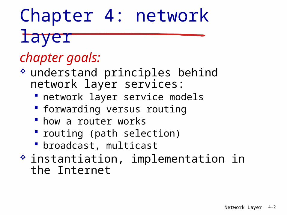
Chapter 4: network layer
chapter goals: understand principles behind network
layer services: network layer service models forwarding versus routing how a router works routing (path selection) broadcast, multicast
instantiation, implementation in the Internet
Network Layer 4-3
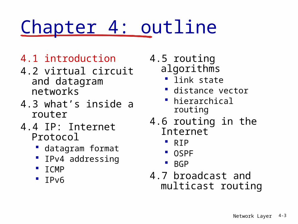
4.1 introduction4.2 virtual circuit and
datagram networks4.3 what’s inside a
router4.4 IP: Internet Protocol
datagram format IPv4 addressing ICMP IPv6
4.5 routing algorithms link state distance vector hierarchical routing
4.6 routing in the Internet RIP OSPF BGP
4.7 broadcast and multicast routing
Chapter 4: outline
Network Layer 4-4
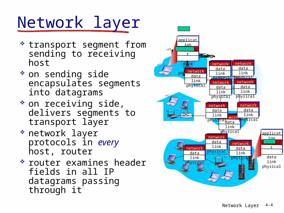
Network layer transport segment from
sending to receiving host
on sending side encapsulates segments into datagrams
on receiving side, delivers segments to transport layer
network layer protocols in every host, router
router examines header fields in all IP datagrams passing through it
applicationtransportnetworkdata linkphysical
applicationtransportnetworkdata linkphysical
networkdata linkphysical network
data linkphysical
networkdata linkphysical
networkdata linkphysical
networkdata linkphysical
networkdata linkphysical
networkdata linkphysical
networkdata linkphysical
networkdata linkphysical
networkdata linkphysicalnetwork
data linkphysical
Network Layer 4-5
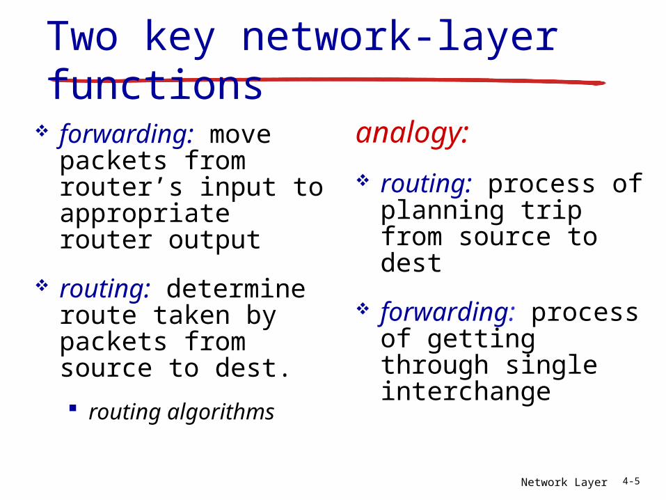
Two key network-layer functions
forwarding: move packets from router’s input to appropriate router output
routing: determine route taken by packets from source to dest.
routing algorithms
analogy:
routing: process of planning trip from source to dest
forwarding: process of getting through single interchange
Network Layer 4-6
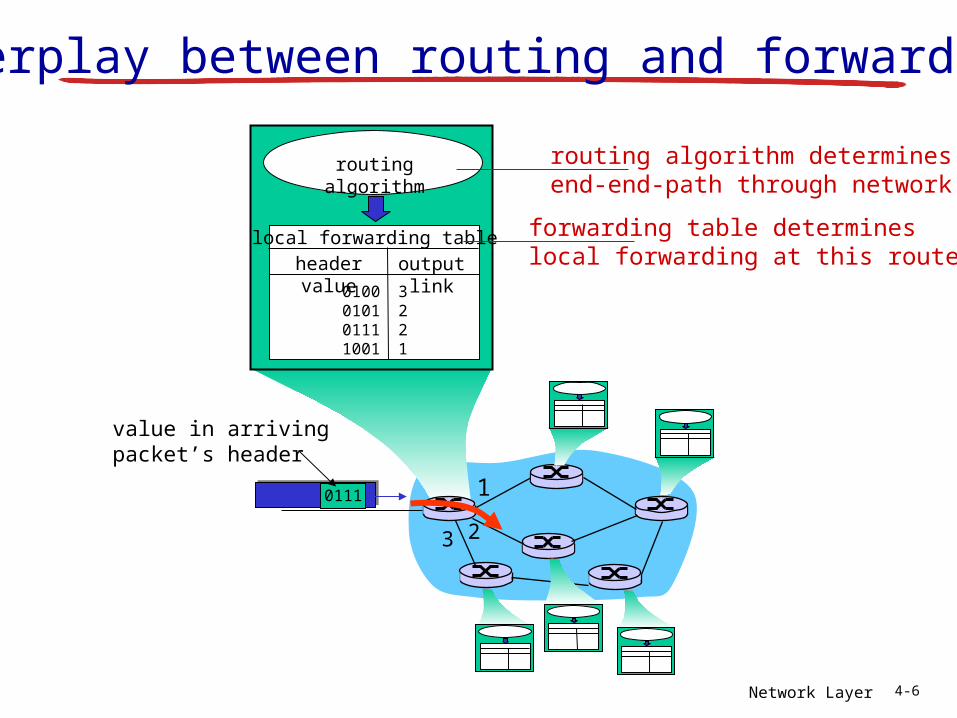
1
23
0111
value in arrivingpacket’s header
routing algorithm
local forwarding tableheader value output link
0100010101111001
3221
Interplay between routing and forwarding
routing algorithm determinesend-end-path through network
forwarding table determineslocal forwarding at this router
Network Layer 4-7
Connection setup
3rd important function in some network architectures: ATM, frame relay, X.25
before datagrams flow, two end hosts and intervening routers establish virtual connection routers get involved
network vs transport layer connection service: network: between two hosts (may also involve
intervening routers in case of VCs) transport: between two processes
Network Layer 4-8
Network service modelQ: What service model for “channel” transporting datagrams from sender to receiver?
example services for individual datagrams:
guaranteed delivery guaranteed delivery
with less than 40 msec delay
example services for a flow of datagrams:
in-order datagram delivery
guaranteed minimum bandwidth to flow
restrictions on changes in inter-packet spacing
Network Layer 4-9
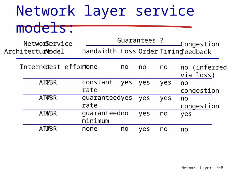
Network layer service models:
NetworkArchitecture
Internet
ATM
ATM
ATM
ATM
ServiceModel
best effort
CBR
VBR
ABR
UBR
Bandwidth
none
constantrateguaranteedrateguaranteed minimumnone
Loss
no
yes
yes
no
no
Order
no
yes
yes
yes
yes
Timing
no
yes
yes
no
no
Congestionfeedback
no (inferredvia loss)nocongestionnocongestionyes
no
Guarantees ?
Network Layer 4-10
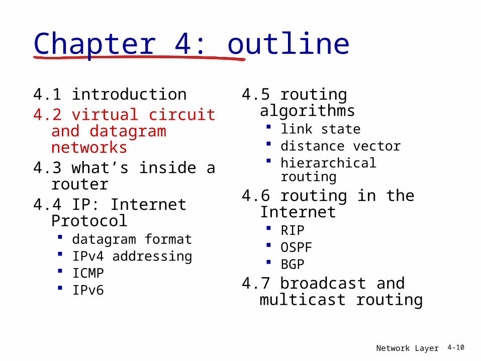
4.1 introduction4.2 virtual circuit and
datagram networks4.3 what’s inside a
router4.4 IP: Internet Protocol
datagram format IPv4 addressing ICMP IPv6
4.5 routing algorithms link state distance vector hierarchical routing
4.6 routing in the Internet RIP OSPF BGP
4.7 broadcast and multicast routing
Chapter 4: outline
Network Layer 4-11
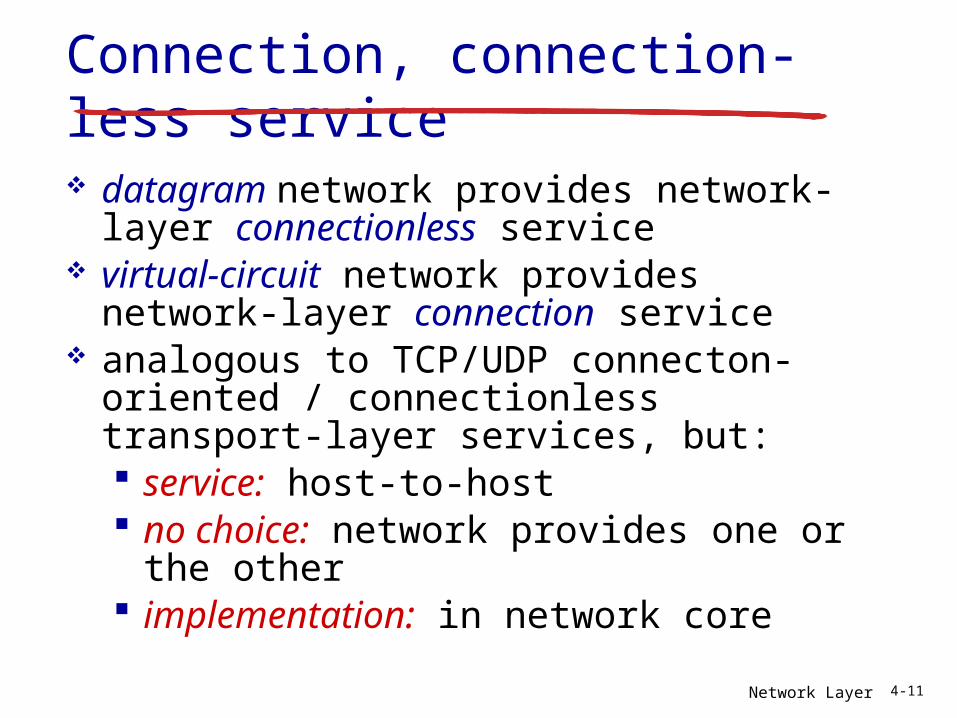
Connection, connection-less service datagram network provides network-
layer connectionless service virtual-circuit network provides network-
layer connection service analogous to TCP/UDP connecton-
oriented / connectionless transport-layer services, but: service: host-to-host no choice: network provides one or
the other implementation: in network core
Network Layer 4-12
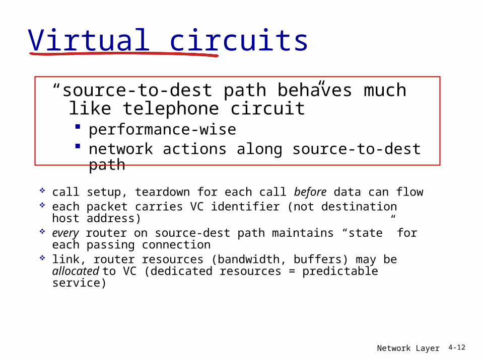
Virtual circuits
call setup, teardown for each call before data can flow each packet carries VC identifier (not destination host
address) every router on source-dest path maintains “state” for
each passing connection link, router resources (bandwidth, buffers) may be
allocated to VC (dedicated resources = predictable service)
“source-to-dest path behaves much like telephone circuit” performance-wise network actions along source-to-dest path
Network Layer 4-13
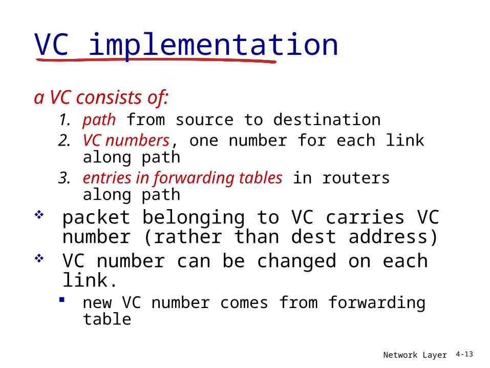
VC implementation
a VC consists of:1. path from source to destination2. VC numbers, one number for each link
along path3. entries in forwarding tables in routers
along path packet belonging to VC carries VC
number (rather than dest address) VC number can be changed on each
link. new VC number comes from forwarding
table
Network Layer 4-14
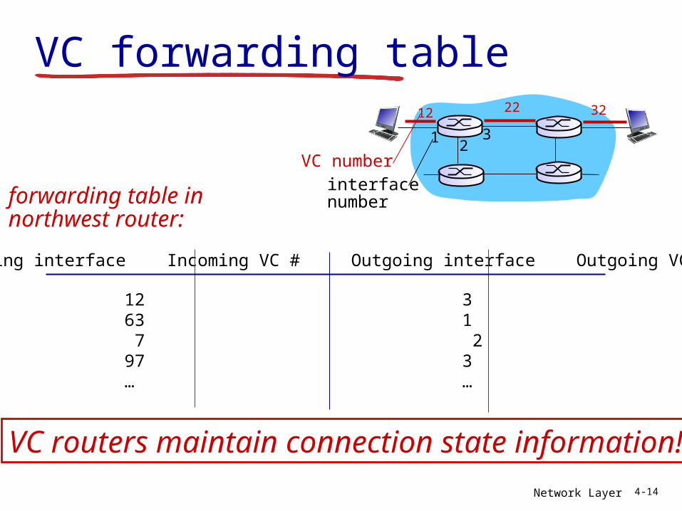
VC forwarding table12 22 32
12
3
VC numberinterfacenumber
Incoming interface Incoming VC # Outgoing interface Outgoing VC #
1 12 3 222 63 1 18 3 7 2 171 97 3 87… … … …
forwarding table innorthwest router:
VC routers maintain connection state information!
Network Layer 4-15
applicationtransportnetworkdata linkphysical
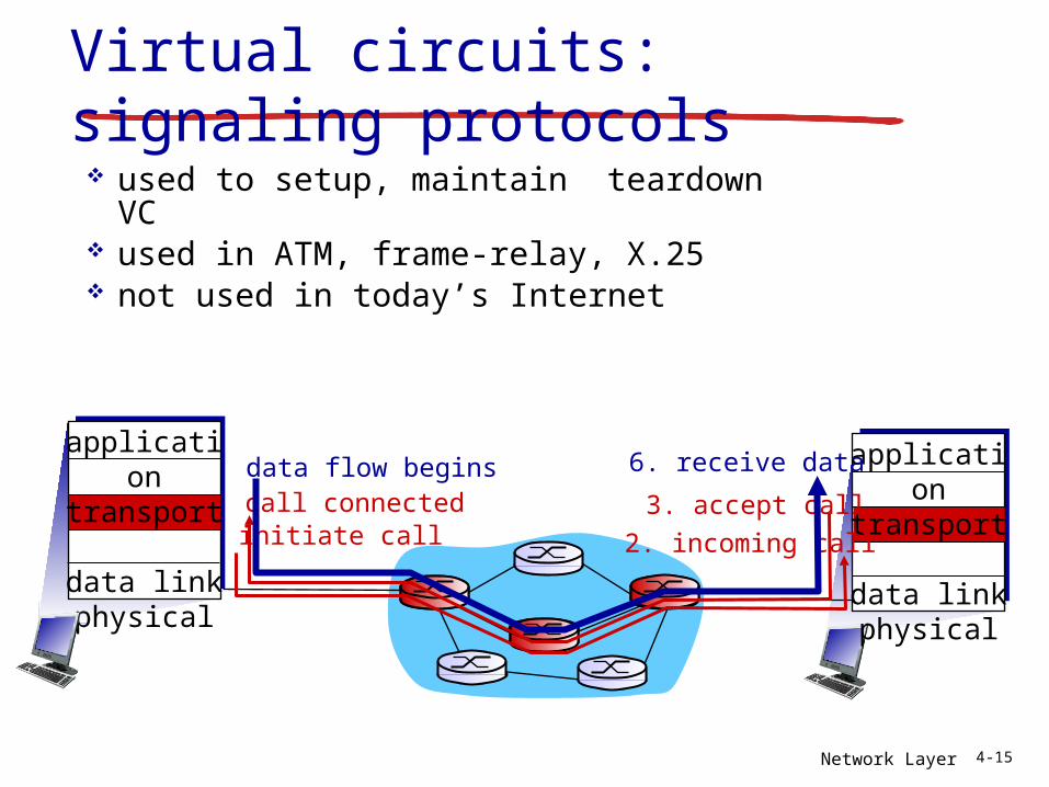
Virtual circuits: signaling protocols used to setup, maintain teardown VC used in ATM, frame-relay, X.25 not used in today’s Internet
1. initiate call 2. incoming call
3. accept call4. call connected5. data flow begins 6. receive data
applicationtransportnetworkdata linkphysical
Network Layer 4-16
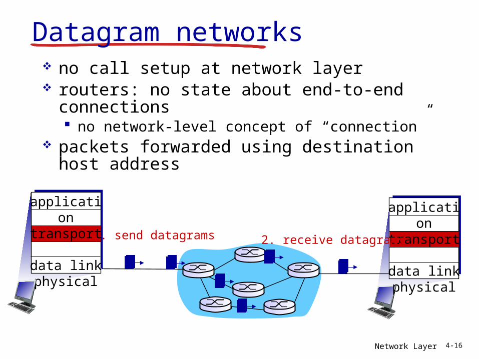
Datagram networks no call setup at network layer routers: no state about end-to-end
connections no network-level concept of “connection”
packets forwarded using destination host address
1. send datagrams
applicationtransportnetworkdata linkphysical
applicationtransportnetworkdata linkphysical
2. receive datagrams
Network Layer 4-17
1
23
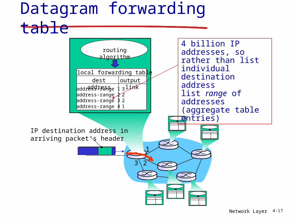
Datagram forwarding table
IP destination address in arriving packet’s header
routing algorithm
local forwarding tabledest address output
linkaddress-range 1address-range 2address-range 3address-range 4
3221
4 billion IP addresses, so rather than list individual destination addresslist range of addresses(aggregate table entries)
Network Layer 4-18
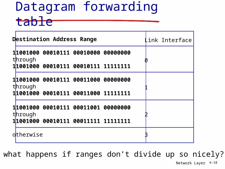
Destination Address Range
11001000 00010111 00010000 00000000through 11001000 00010111 00010111 11111111
11001000 00010111 00011000 00000000through11001000 00010111 00011000 11111111
11001000 00010111 00011001 00000000through11001000 00010111 00011111 11111111
otherwise
Link Interface
0
1
2
3
Q: but what happens if ranges don’t divide up so nicely?
Datagram forwarding table
Network Layer 4-19
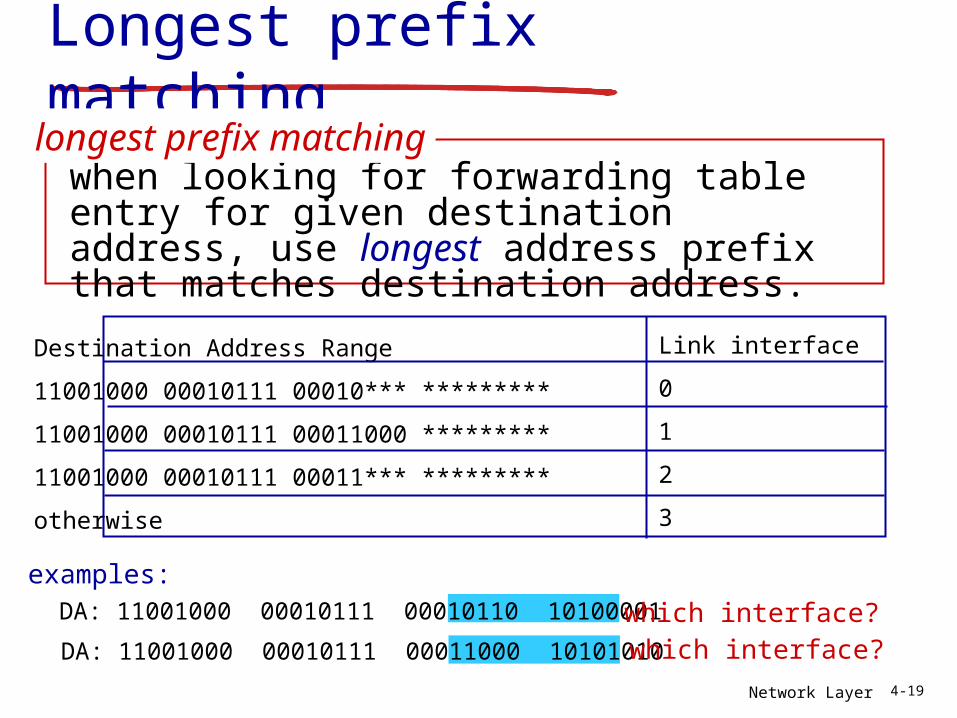
Longest prefix matching
Destination Address Range
11001000 00010111 00010*** *********
11001000 00010111 00011000 *********
11001000 00010111 00011*** *********
otherwise
DA: 11001000 00010111 00011000 10101010
examples:DA: 11001000 00010111 00010110 10100001 which interface?
which interface?
when looking for forwarding table entry for given destination address, use longest address prefix that matches destination address.
longest prefix matching
Link interface
0
1
2
3
Network Layer 4-20
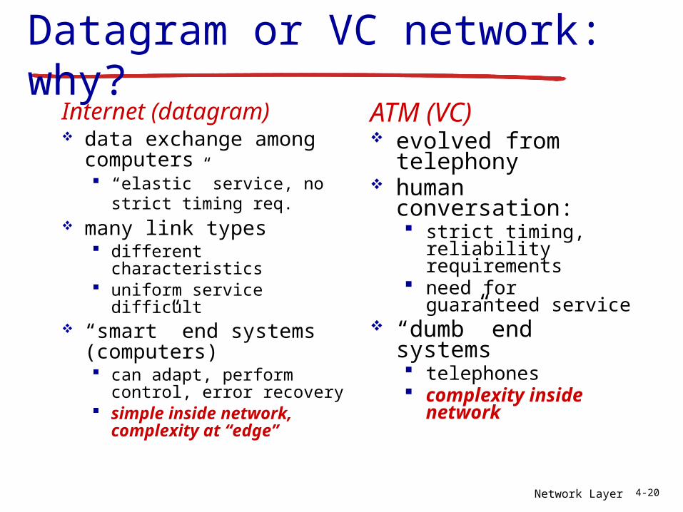
Datagram or VC network: why?
Internet (datagram) data exchange among
computers “elastic” service, no strict
timing req. many link types
different characteristics uniform service difficult
“smart” end systems (computers) can adapt, perform
control, error recovery simple inside
network, complexity at “edge”
ATM (VC) evolved from
telephony human conversation:
strict timing, reliability requirements
need for guaranteed service
“dumb” end systems telephones complexity inside
network
Network Layer 4-21
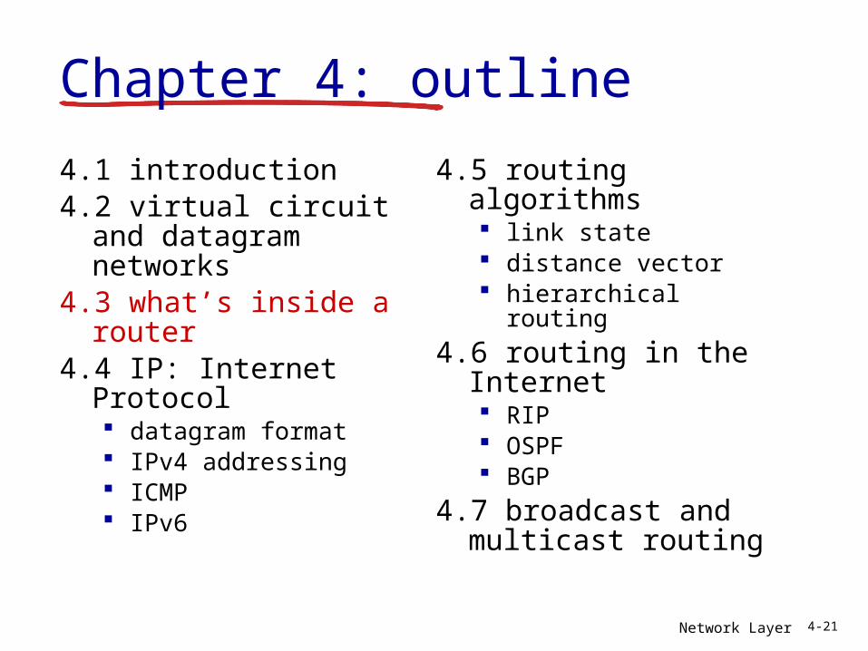
4.1 introduction4.2 virtual circuit and
datagram networks4.3 what’s inside a
router4.4 IP: Internet Protocol
datagram format IPv4 addressing ICMP IPv6
4.5 routing algorithms link state distance vector hierarchical routing
4.6 routing in the Internet RIP OSPF BGP
4.7 broadcast and multicast routing
Chapter 4: outline
Network Layer 4-22
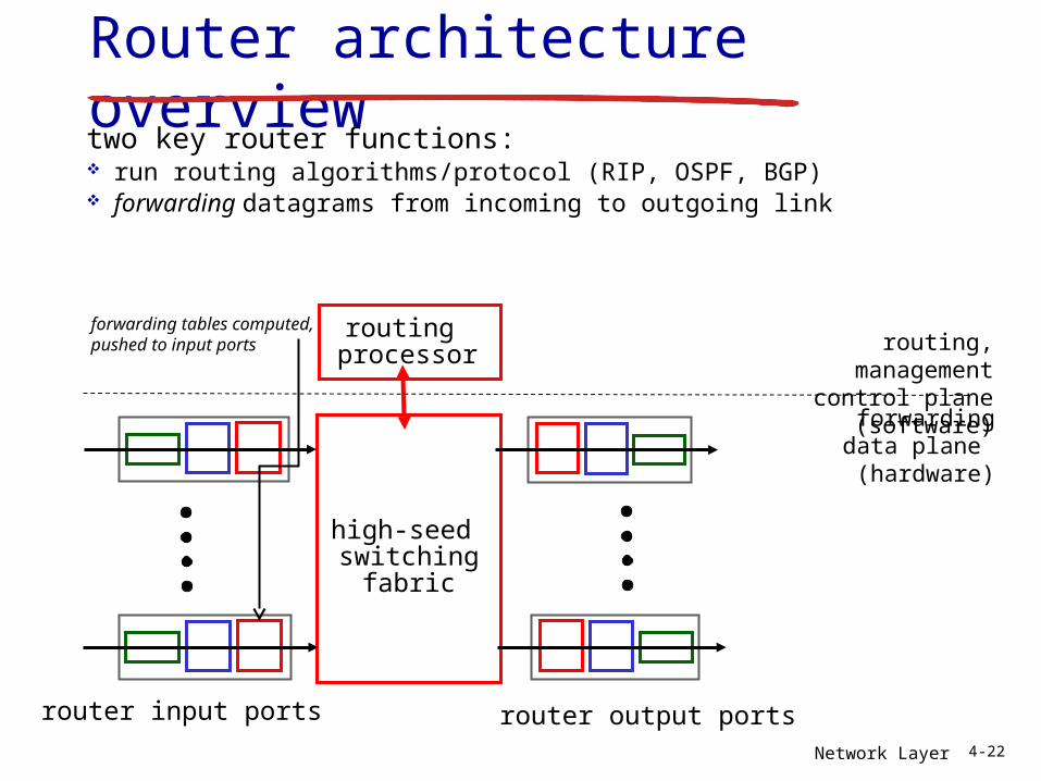
Router architecture overviewtwo key router functions: run routing algorithms/protocol (RIP, OSPF, BGP) forwarding datagrams from incoming to outgoing link
high-seed switching
fabric
routing processor
router input ports router output ports
forwarding data plane (hardware)
routing, managementcontrol plane (software)
forwarding tables computed,pushed to input ports
Network Layer 4-23
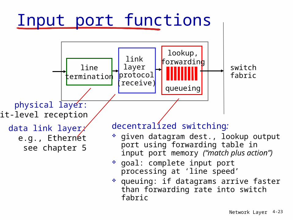
linetermination
link layer
protocol(receive)
lookup,forwarding
queueing
Input port functions
decentralized switching: given datagram dest., lookup output
port using forwarding table in input port memory (“match plus action”)
goal: complete input port processing at ‘line speed’
queuing: if datagrams arrive faster than forwarding rate into switch fabric
physical layer:bit-level reception
data link layer:e.g., Ethernetsee chapter 5
switchfabric
Network Layer 4-24
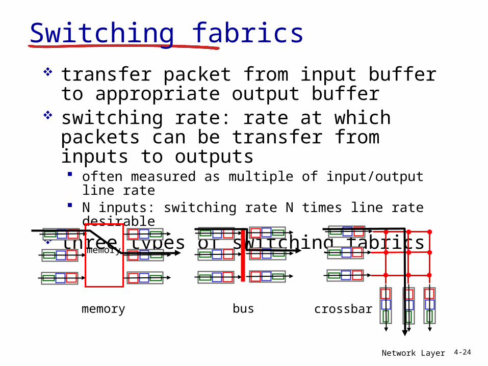
Switching fabrics transfer packet from input buffer to
appropriate output buffer switching rate: rate at which packets
can be transfer from inputs to outputs often measured as multiple of input/output line rate N inputs: switching rate N times line rate desirable
three types of switching fabrics
memory
memory
bus crossbar
Network Layer 4-25
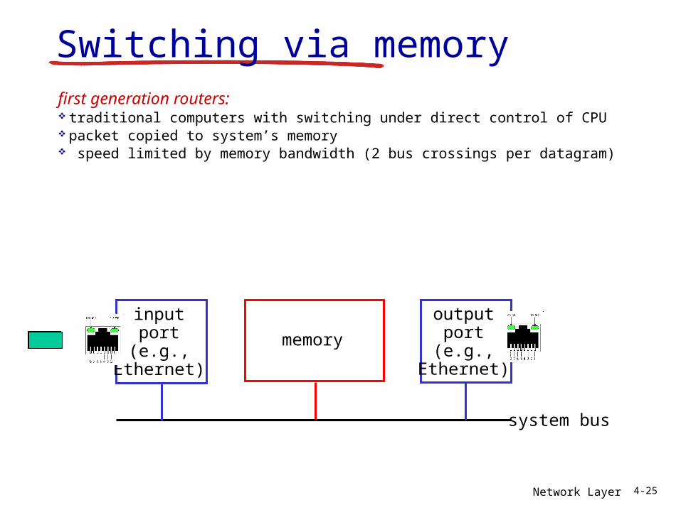
Switching via memoryfirst generation routers: traditional computers with switching under direct control of CPU packet copied to system’s memory speed limited by memory bandwidth (2 bus crossings per datagram)
inputport
(e.g.,Ethernet)
memory
outputport
(e.g.,Ethernet)
system bus
Network Layer 4-26
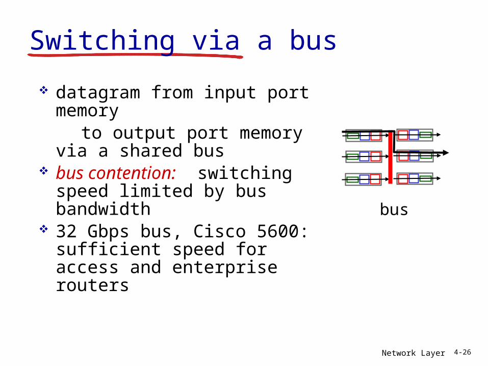
Switching via a bus
datagram from input port memory
to output port memory via a shared bus
bus contention: switching speed limited by bus bandwidth
32 Gbps bus, Cisco 5600: sufficient speed for access and enterprise routers
bus
Network Layer 4-27
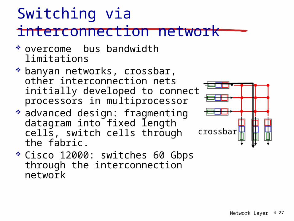
Switching via interconnection network overcome bus bandwidth
limitations banyan networks, crossbar,
other interconnection nets initially developed to connect processors in multiprocessor
advanced design: fragmenting datagram into fixed length cells, switch cells through the fabric.
Cisco 12000: switches 60 Gbps through the interconnection network
crossbar
Network Layer 4-28
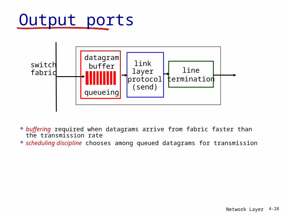
Output ports
buffering required when datagrams arrive from fabric faster than the transmission rate
scheduling discipline chooses among queued datagrams for transmission
linetermination
link layer
protocol(send)
switchfabric
datagrambuffer
queueing
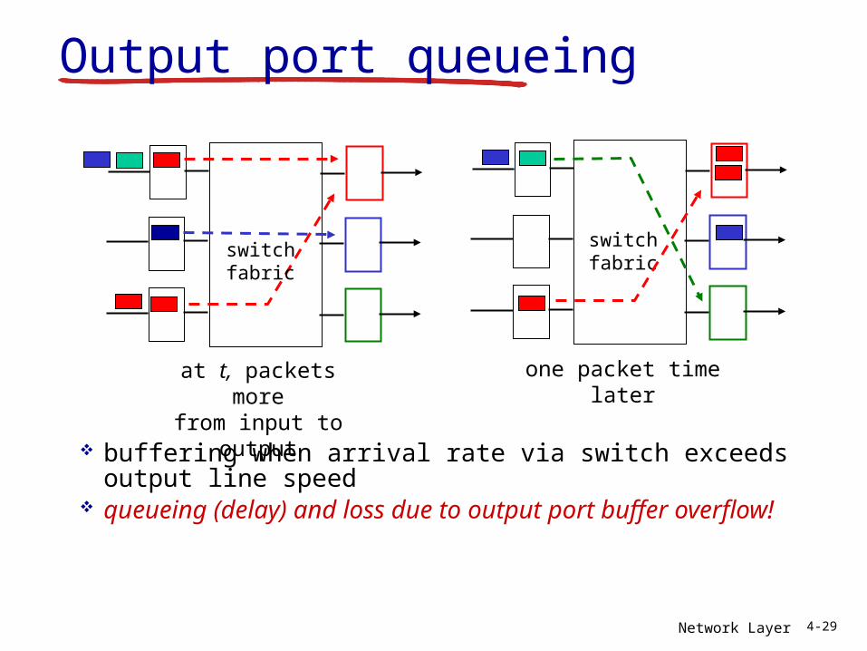
Network Layer 4-29
Output port queueing
buffering when arrival rate via switch exceeds output line speed
queueing (delay) and loss due to output port buffer overflow!
at t, packets morefrom input to output
one packet time later
switchfabric
switchfabric
Network Layer 4-30
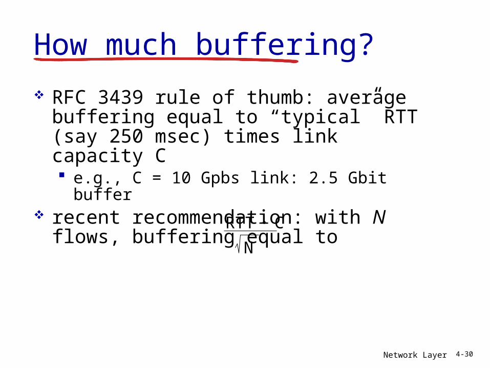
How much buffering?
RFC 3439 rule of thumb: average buffering equal to “typical” RTT (say 250 msec) times link capacity C e.g., C = 10 Gpbs link: 2.5 Gbit buffer
recent recommendation: with N flows, buffering equal to
RTT C.N
Network Layer 4-31
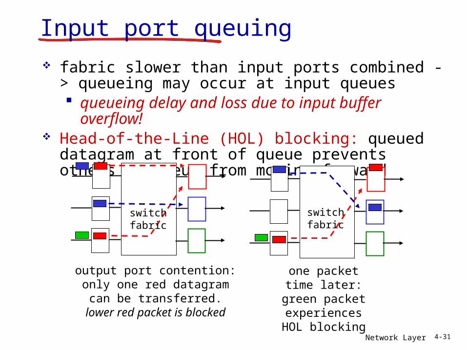
Input port queuing fabric slower than input ports combined ->
queueing may occur at input queues queueing delay and loss due to input buffer
overflow! Head-of-the-Line (HOL) blocking: queued
datagram at front of queue prevents others in queue from moving forward
output port contention:only one red datagram can
be transferred.lower red packet is blocked
switchfabric
one packet time later: green
packet experiences HOL
blocking
switchfabric