1. Introduction - me.umn. · PDF file1. Introduction Background PLC - Programmable Logic...
28
ME 4231 – Motion Control Lab 1. Introduction Background PLC - Programmable Logic Controller • Origin - GM in 1968 • Original goals: • programmable • communication capable • maintainable • reliable • compact • inexpensive • Additional features: • discrete & continuous control • MMI • PLC structure: Programming Language RLL - Relay Ladder Logic • History: RLL was documentation standard for relay panels • Relay terminology Program Terminal CPU / Memory I/O Modules NC Contact NO Contact Coil
Transcript of 1. Introduction - me.umn. · PDF file1. Introduction Background PLC - Programmable Logic...
ME 4231 – Motion Control Lab
1. Introduction
Background
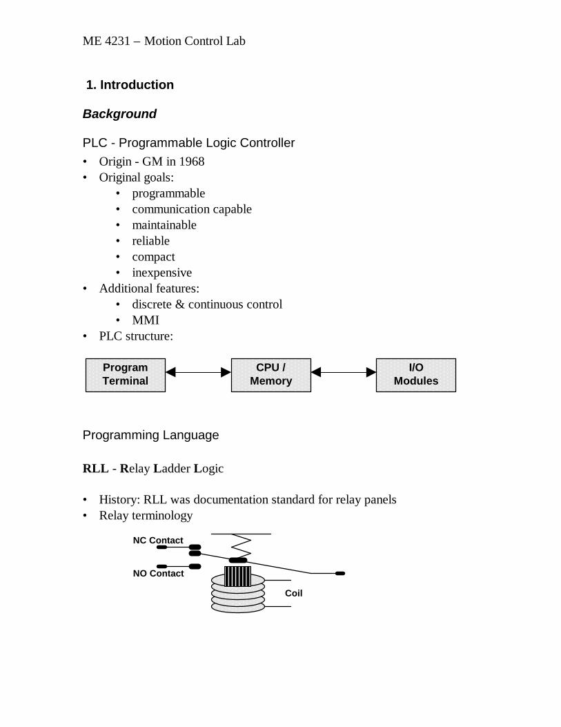
PLC - Programmable Logic Controller• Origin - GM in 1968• Original goals:
• programmable• communication capable• maintainable• reliable• compact• inexpensive
• Additional features:• discrete & continuous control• MMI
• PLC structure:
Programming Language
RLL - Relay Ladder Logic
• History: RLL was documentation standard for relay panels• Relay terminology
ProgramTerminal
CPU /Memory
I/OModules
NC Contact
NO Contact
Coil

ME 4231 – Motion Control Lab
• Programming elements• Normally Open (NO) contact
• Normally Closed (NC) contact
• Coil
• Connectors (shorts)
• Timer
• Counter
• “Relay” operation• A normally open (NO) contact passes power when the associated
coil (or input) is on.• A normally closed (NC) contact passes power when the associated
coil (or input) is off.• A given coil (or input) can be associated with any number of both
normally open and normally closed contacts.
• Timer / Counter operation• Timer runs, increasing the (integer) accumulated value, when accum
< preset & both inputs (“in” & “enable/reset”) are on.• Counter increases the accumulated value when accum < preset, the
bottom input “enable/reset” is on, and the top input “in” goes on.• Output (“out”) is on when accum = preset.• “Accum” is reset to zero when enable/reset is off.
preset
Tx.xxxaccum
in
enable/reset inverse out
out
preset
U/DCTRaccum
in
enable/reset inverse out
out

ME 4231 – Motion Control Lab
Example: Oscillator
Timing Diagram
Note: Gould-Modicon numbering convention:• 0xxxx: outputs (normally > 00012 are internal coils)• 1xxxx: inputs (normally 10001 through 10016)• 4xxxx: counter & timer values
00001
00101
00001
00001
00101
10001#0002
T1.040001
#0003
T1.040002
2 s 3 s 2 s 3 s
10001
00001
00101
ME 4231 – Motion Control Lab
2. RLL Design Strategy
Coffee Maker Example
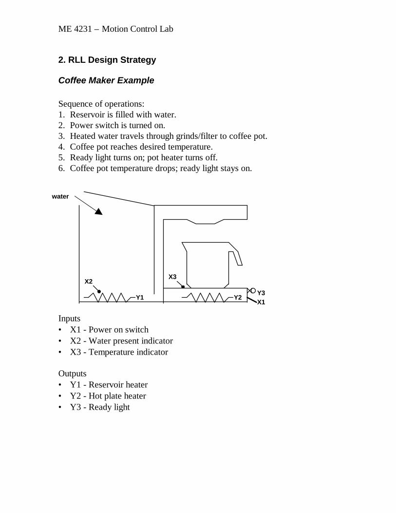
Sequence of operations:1. Reservoir is filled with water.2. Power switch is turned on.3. Heated water travels through grinds/filter to coffee pot.4. Coffee pot reaches desired temperature.5. Ready light turns on; pot heater turns off.6. Coffee pot temperature drops; ready light stays on.
Inputs• X1 - Power on switch• X2 - Water present indicator• X3 - Temperature indicator
Outputs• Y1 - Reservoir heater• Y2 - Hot plate heater• Y3 - Ready light
X2
Y2Y1X1Y3
X3
water

ME 4231 – Motion Control Lab
Coffee Maker: Timing Diagram
Coffee Maker: RLL Program
X1
X2
X3
Y1
Y2
Y3
X1
Y3
X3
X1
X2X1 Y1
X2 X3 Y2
Y3X2

ME 4231 – Motion Control Lab
Street Light Strategy
Timing Diagram
Divide problem into steps - how many steps?
Proposal: assign one internal coil to each step. Add these coils to the timingdiagram:
Green 1
Yellow 1
Red 1
Green 2
Yellow 2
Red 2
0 35 5540 60
Coil 1
Coil 2
Coil 3
Coil 4
0 35 5540 60

ME 4231 – Motion Control Lab
Program the internal coils first:
etc.
Program the outputs using the coils, referring to the timing diagram. Forexample:
etc.
Remaining problem is to reset the system correctly.
00102 (C2)
00104
00101
00104
10001#0035
T1.040001
#0005
T1.040002
00101 (C1)
00101
00101 Y1
00102 Y2

ME 4231 – Motion Control Lab
3. RLL Programming ExampleGiven the following RLL code and the operation of input 10001, complete thetiming diagram for coils 00101 and 00102.
Steam Cooker Example
Sequence of operations:1. The start button is momentarily closed, starting the pump.2. The tank fills, activating first the low-level, then the high-level sensor.
Then the pump stops.3. The steam valve opens, raising the temperature until the temperature
indicator is activated.4. Ten minutes after the desired temperature is reached, the steam shuts off
and the drain valve opens.5. The tank empties, de-activating first the high-level, then the low-level
sensor. Then the drain valve closes.6. Steps 1-5 are repeated.
00102
10001
00101
00101
10001#0003
T1.040001
#0002
UCTR40002
00101
10001
00101
001020 105
0 105
pump
steam drainY2 Y3
Y1
start
X4
X3- low level
X1- high level
X2temp

ME 4231 – Motion Control Lab
Inputs:• X1 - High level indicator switch (on = full)• X2 - Temperature indicator (on = hot)• X3 - Low level indicator (off = empty)• X4 - Start button (on = pushed - momentary)
Outputs:• Y1 – Pump• Y2 – Steam valve• Y3 – Drain valve
Steam Cooker Timing Diagram
X1
X2
X4
X3
Y2
Y3
Y1

ME 4231 – Motion Control Lab
RLL Program – Steam Cooker
Pump
Drain valve00003
10003
10002
00001
10004
#0600
T1.040001
0000110003 10001
10001 00003Steam valve
00002

ME 4231 – Motion Control Lab
4. RLL Programming Example (2)Given the following RLL code and the operation of input 10001, complete thetiming diagram for coils 00101 and 00102.
Packaging Device Example
Sequence of operations:1. Power is turned on, starting conveyor.2. Widget traveling on conveyor is detected.3. Solenoid activates pneumatic cylinder, loading widget into box.4. Cylinder reaches end of stroke and pauses.5. Cylinder returns to home position.6. Steps 2-5 are repeated until box is full (12 widgets).7. Conveyor stops and waits for restart button.
00102
10001
00101
00101
10001
#0002
T1.040001
0010100102
10001
00101
001020 105
0 105

ME 4231 – Motion Control Lab
Inputs:• X1 - Power On switch (momentary closed)• X2 - Stop switch (momentary open)• X3 - Cycle Start switch (momentary closed)• X4 - Photo detector (normally open)• X5 - Cylinder left limit switch (normally open)• X6 - Cylinder right limit switch (normally open)Outputs:• Y1 - Conveyor• Y2 - Cylinder right• Y3 - Cylinder left
Functional Requirements:1. X1 must remain closed for 2 seconds to turn on the machine. After 2
seconds, machine stays on when switch is released.2. The cycle start button X3 must be pushed to start the conveyor Y1.3. If X2 is pushed, machine turns and remains off until restarted with X1.4. Cylinder right Y2 is activated 0.2 seconds after part is detected (X4 is
opened), and remains on until X6 is closed.5. Cylinder left Y3 is activated 0.1 seconds after cylinder move right is
completed (X6 is closed), and remains on until X5 is closed.6. Steps 3 & 4 are repeated 12 times, and then the machine stops until the
cycle start button is pushed again.
X1 X2 X3
PowerOn
Stop CycleStart
air return
Y2 Y3
X5 X6
conveyor
Y1
widget X4
To box

ME 4231 – Motion Control Lab
Packaging Device Timing Diagram:
X1
X2
X4
X6
X5
X3
Y2
Y3
C1
C2
C3
C4
Y1

ME 4231 – Motion Control Lab
RLL Program: Packaging Device
00001
10003
00101
00101
10002
10001#0020
T0.140001
00101
00102
10006
10004#0002
T0.140002
00103
10005
10006#0001
T0.140003
10003
10006 00104#00012
UCTR40004
10005
00102 00104 00002
00103 00104 00003
Power On
Box Full
Part Ready
Part Loaded
00104 00001Conveyor
Cylinder Right
Cylinder Left

ME 4231 – Motion Control Lab
5. USING REGISTERS
In a timer or counter, there are two numbers that the PLC stores and refers to:• accum• presetWhen setting up a timer or counter, an address (4xxxx) must be supplied forthe accum value, since the program causes this number to change as the timeincrements. The preset may be either an address or a constant value - up tothis point we have used only constants for the preset.
Example: Timer using an address for the preset
Register table (access through register/edit menu):
Time: 0 1 2 3 4 5 6 7 800001 0 0 0 1 1 1 1 0 010001 1 1 1 1 1 1 1 0 040001 3 3 3 3 3 3 3 3 340002 0 1 2 3 3 3 3 0 0
Notes:• Registers 0xxxx and 1xxxx can only be 1 or 0.• Register 4xxxx can be any integer (max 32767)
10001
10001 0000140001
T1.040002
10001
00001
0 1 2 3 4 5 6 7 8

ME 4231 – Motion Control Lab
Steam Cooker Example
Time: 0 500 1000 1500 2000 2500 3000000010000200003100011000210003100044000140002 600 600 600 600 600 600 600
X1
X2
X4
X3
Y2
Y3
Y1
Pump
Drain valve00003
10003
10002
00001
10004
40002
T1.040001
0000110003 10001
10001 00003Steam valve
00002
0 500 1000 1500 2000 2500 3000

ME 4231 – Motion Control Lab
6. BLKM Programming
Understanding registers (especially accum) is necessary for MMIprogramming – the MMI program uses the register information to illustratethe process on the computer screen.
Using addresses for preset is mainly useful if it can be changed by theprogram. We will accomplish this with the BLKM command.
BLKM operation• The register values in the source registers are copied to the destination
registers each logic cycle while the “input” is on.• When the “input” is on and the registers have been copied, the “output” is
turned on.• “Source” refers to the address of the first register to be copied.• “Dest” refers to the address to which the first register is copied.• “Length”is the number of consecutive registers to be copied. For
example, if length = 3, the source register and the next two are copied tothe destination register and the next two.
source
destBLKM
length
input output

ME 4231 – Motion Control Lab
BLKM Example
1000210001 0010140021
40011BLKM
2
10002 10001 0010240031
40011BLKM
2
00103
00102
00101 00103
000010010340012
T1.040001
00103

ME 4231 – Motion Control Lab
Time: 0 1 2 3 4 5 610001 0 1 1 1 1 0 010002 0 0 1 1 0 0 00000100101001020010340001400114001240021 1 1 1 1 1 1 140022 2 2 2 2 2 2 240031 3 3 3 3 3 3 340032 4 4 4 4 4 4 4

ME 4231 – Motion Control Lab
Given the following RLL program, complete the timing diagram and fill in thetable of register values at t=10 seconds.
40001 40002 40021 40022 40051 40052 40061 40062
T=0 0 0 0 0 1 2 3 4T=10
00104
00104
00104
00102
00101
10001
10001
10001 00101
00102
#0003
T1.040001
40051
40021BLKM
2
0010340061
40021BLKM
2
00101 00104
0000140022
T1.040002
00103

ME 4231 – Motion Control Lab
10001
00101
001020 105
0 10500103
0 10500104
0 10500001
0 105
ME 4231 – Motion Control Lab
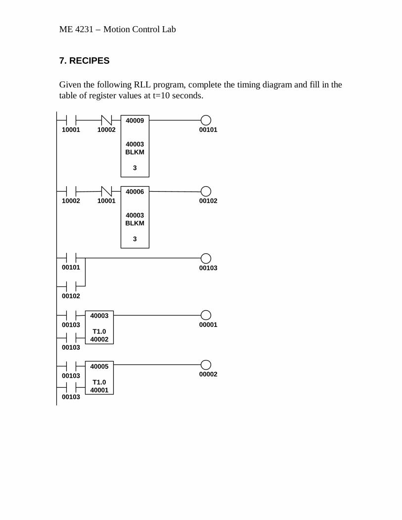
7. RECIPES
Given the following RLL program, complete the timing diagram and fill in thetable of register values at t=10 seconds.
00103
00103
00102
00101
10002
10002 0010140009
40003BLKM
3
00102
00103
0000140003
T1.040002
10001
1000140006
40003BLKM
3
00103
00103 0000240005
T1.040001

ME 4231 – Motion Control Lab
T=0 T=1040001 040002 040003 040004 040005 040006 140007 240008 340009 440010 540011 6
RECIPE EXAMPLE: Ice Cream Maker
Ingredients: Premix (eggs, cream, sugar, etc.), vanilla, strawberry, chocolate
Outputs:• Premix dispenser 00001• Vanilla dispenser 00002• Strawberry dispenser 00003• Chocolate dispenser 00004• Mixer 00005
Recipes:
Vanilla Strawberry ChocolatePremix 5 5 6Vanilla 1.5 .3 .2
Strawberry 0 1.3 0Chocolate 0 0 .5Mix Time 30 35 40
10001
00101
001020 105
0 10500103
0 10500001
0 10500002
0 105
10002

ME 4231 – Motion Control Lab
Initial Register Values:
Recipe Vanilla Strawberry Chocolate40101 0 40111 50 40121 50 40131 6040102 0 40112 15 40122 3 40132 240103 0 40113 0 40123 13 40133 040104 0 40114 0 40124 0 40134 540105 0 40115 30 40125 35 40135 40
Inputs:• Start button 10001• Select Vanilla 10002• Select Strawberry 10003• Select Chocolate 10004
00021
00001
00026
00023
10001
00021
0002140102
T0.140002
00021
000220002140101
T0.140001
00021
00021 00022
0000200021 00023

ME 4231 – Motion Control Lab
000240002140103
T0.140003
00021
0000300021 00024
000250002140104
T0.140004
000260000540105
T1.040005
00021
0000400021 00025
0000500022 00023 00024 00025 00026
00021
00029 00027
40111
40101BLKM
5
10002 00028
00029 00028
40121
40101BLKM
5
10003 00027
00028 00029
40131
40101BLKM
5
10004 00027

ME 4231 – Motion Control Lab
8. ExamplesGiven the following RLL program, complete the timing diagram and fill in thetable of register values at t=10 seconds.
RegisterT=0
T=10
40001 040002 040003 040011 240012 340013 440021 140022 240023 3
00101
00104
10001
00104
00102
00102
00101 00102
00103
40011
T1.040001
40021
40011BLKM
3
0000140013
UCTR40003
00104
0010340012
T1.040002
10001 0010100102
1000101
0 5
1000102
0 5
1000104
0 5
1000001
0 5
10001
001030 5 10

ME 4231 – Motion Control Lab
Given the following RLL program, complete the timing diagram and fill in thetable of register values at t=10 seconds.
RegisterT=0
T=10
40001 040002 040003 340004 440005 540006 140007 240008 340009 340010 040011 040012 0
00101
00104
0010210001
00102
00102
00101 00102
00103
40011
T1.040001
40009
UCTR40002
0000140006
40010BLKM
3
0010240003
40010BLKM
3
10001
10001 00101
00103
10001
1000101
0 5
1000102
0 5
1000104
0 5
1000001
0 5
10001
001030 5 10
00103

ME 4231 – Motion Control Lab
9. REVIEW
Given the following RLL program, complete the timing diagram and fill in thetable of register values at t=10 seconds.
RegisterT=0
T=10
40001 040002 040003 040011 140012 140021 440022 740031 340032 2
00104
10001
00104
00101
10001
10001
00102 00101
00102
40021
T1.040001
40031
40021BLKM
2
0010340021
40011BLKM
2
0000140022
UCTR40003
00104
0010340012
T1.040002
10001
1000101
0 5
1000102
0 5
1000104
0 5
1000001
0 5
001030 5 10