1. Historical Development of SSDMs -...
26
Chapter 1 – Historical Development of SSDMs 16 April, 1999 Notes 1 1. Historical Development of SSDMs 1.1. In Days of Yore The development of software system design methods has been something of a melting pot. The earliest programmable computers were used by mathematicians and physicists for solving very difficult problems (e.g. Bletchley Park which cracked the Enigma code and the Manhattan Project which developed the atom bomb). Later on other sciences like chemistry and astronomy would make use of the new digital computers. Engineers would use computers for solving design problems. Out of this emerged the so-called discipline of computer science which found its own uses for the ever larger machines. Figure 1 As computers became more powerful and more groups were able to use them, so more and more people developed software to run on the machines. The development of the transistor allowed computer memories to grow rapidly; consequently installed software also grew in size and complexity. By the time
Transcript of 1. Historical Development of SSDMs -...

Chapter 1 – Historical Development of SSDMs
16 April, 1999
Notes
1
1. Historical Development ofSSDMs
1.1. In Days of Yore
The development of software system design methods has been something of amelting pot. The earliest programmable computers were used bymathematicians and physicists for solving very difficult problems (e.g. BletchleyPark which cracked the Enigma code and the Manhattan Project whichdeveloped the atom bomb). Later on other sciences like chemistry andastronomy would make use of the new digital computers. Engineers would usecomputers for solving design problems. Out of this emerged the so-calleddiscipline of computer science which found its own uses for the ever largermachines.
Figure 1
As computers became more powerful and more groups were able to use them, somore and more people developed software to run on the machines. Thedevelopment of the transistor allowed computer memories to grow rapidly;consequently installed software also grew in size and complexity. By the time

Software Systems Planning & Design
Last modified :
Notes
2
large commercial operations such as banks and insurance companies set up theirearly data processing departments the size of software programs had grown somuch that the new third generation languages (3GL) were developed to helpmanage the growing source code size.
Out of all this emerged different styles and practices for designing and writingcomputer programs. Naturally, some approaches were more methodical andrigorous than others. With the increasing problems of software development andmaintenance in the 1960s and '70s (eloquently described by Frederick Brooks1)came an acceptance that some "structured" approach was needed. The early '70ssaw the emergence of so-called "structured programming" which Jackson'scelebrated JSP method2 coming along in 1975.
We are now in the position of being able to choose from a range of differentmethods each designed to meet specific needs within the software developmentindustries.
Figure 2 The SSDM Domain
A good general purpose design method should aim to address all stages of thesystem development lifecycle. As we shall see, not all methods attempt toaddress every aspect.
1.2. Early methods
The development of methods of systems design has followed a path which hasbeen much criticised, wrongly in our view. Methods have evolved which haveallowed the building of systems of considerable complexity and utility. Themajor problem is that user requirements for change have occurred at analarming rate and hardware technology has progressed at a rate which hasexceeded many expectations and has in fact fuelled many of the requests forchange. Add to this the growing realisation that change is necessary for rapidbusiness growth and is at least easier with computer technology, and it isreadily seen what has put computer systems to the test. The result is that manymethods have not facilitated change, at least not at the rate which is expected ofthem.
The very earliest methods assumed a fairly simplistic life cycle and a fairlycommon pattern of:
• Data capture, followed by
• Data validation, followed by
• Ordering of ‘valid’ data, followed by
• Updating a master file, followed by
1 Brooks, F.P. The Mythical Man Month (Anniversary Edition), Addison-Wesley, 1995.2 Jackson, M.A., Principles of Program Design, Academic Press, 1975.

Chapter 1 – Historical Development of SSDMs
16 April, 1999
Notes
3
• Extraction of required information from the master file.
Later systems merely combined one or more of the above processes. Theproblems of design within such a pattern are:
• What data are required to be kept in the master file(s)? – (the trick here wasto anticipate the information requirements);
• How, when and where to capture and check the basic systems data?;
• How many processes are required in maintaining the systems data andproducing the necessary business information?;
• Matching hardware and systems software to the anticipated applicationsoftware.
The problems were not normally very difficult to solve in a static situation, butbecome enormous in a highly dynamic business environment. Why?
• Because new data requirements tended to necessitate a very large numberof systems changes most particularly in the software;
• New processes tended to affect existing ones often in unpredictable ways;
• The business environment has a much more complex structure than thesimple notion of collect data and transform it into information.
1.3. Evolution
Very rapidly systems analysts/designers started to use a variety ofdiagrammatic aids to describe existing and new systems (not that this was newin itself—in the business world, Organisation and Methods analysts have used anumber of different charting methods for many years). These, in the main, bothclarified the specification of systems and their implementation—when theywere up-to-date. Modern CASE (Computer Aided Software Engineering) toolsusing quite sophisticated graphics techniques aim to eliminate this problem.
While tools were being developed (comparatively slowly), the software designaspects of computer systems concentrated at first on the notions of modularity,top-down development and step-wise refinement culminating in the almostuniversally accepted if ill-defined ‘structured programming’ which was thenextended into various forms of structured systems analysis and design.Although many of the methods overlap and terminology is by no meansuniversally accepted we can at least recognise three basic categories of methodworthy of study:
• Data flow-orientated design;
• Data structure-orientated design, and
• Object-orientated design.
Of these, you will be most familiar with the first two. We shall be reviewingthese and developing a deeper understanding of one of the most specificmethods in the second category (JSD). It is possible to view JSD as having alargely object orientated flavour, and we shall attempt to bring this out.
1.4. Methods/Methodologies
One definition of a methodology is “a collection of procedures, techniques, toolsand documentation aids which will help the systems developers in their efforts toimplement a new system”.

Software Systems Planning & Design
Last modified :
Notes
4
The objectives of methodologies often differ greatly. The following list gives sixreasonable objectives.
1. To record accurately the requirements for an information system.The users must be able to specify their requirements in a way which boththey and the systems developers will understand, otherwise the resultantinformation system will not meet the needs of the users.
2. To provide a systematic method of development in such a way thatprogress can be effectively monitored. Controlling large scale projects isnot easy, and a project which does not meet its deadlines can have seriouscost implications for the organisation. The provision of checkpoints and welldefined stages in a methodology should ensure that project planningtechniques can be effectively applied.
3. To provide an information system within an appropriate time limitand at an acceptable cost. Unless the time spent using some of thetechniques included in some methodologies is limited, it is possible to devotean enormous amount of largely unproductive time attempting to achieveperfection. A methodology reflects pragmatic considerations.
4. To produce a system which is well documented and easy tomaintain. The need for future modifications to the information system isinevitable as a result of changes taking place in the organisation. Thesemodifications should be made with the least effect on the rest of the system.This requires good documentation.
5. To provide an indication of any changes which need to be made asearly as possible in the development process. As an information systemprogresses from analysis through design to implementation, the costsassociated with making changes increases. Therefore the earlier the changesare effected, the better.
6. To provide a system which is liked by those people affected by thatsystem. The people affected by the information system may include clients,managers, auditors, and users. If a system is liked by them, it is more likelythat the system will be used and be successful.
1.5. Stages in SSDM development
Just as we can trace the development of programming languages from firstgeneration languages through to today's fourth-generation environments, so wecan map a generational development of systems methods.
1.5.1. First generation methods
In the first-generation methods of the 1960s developers tended to rely on asingle technique and modelling tool, although various techniques and toolsexisted for varied sets of problems (see the melting pot earlier). These earlymethods made use of the so-called structured techniques associated withprogram design. These centred around functional decomposition as a way ofreducing complexity, a form of divide et impera. Structured design becameingrained and almost innate and spawned the development of techniques suchas data-flow diagramming.
Despite rapid technological changes, there is much inertia in the softwareindustry and many organisations did not adopt any form of structured analysisand design until the 1980s.

Chapter 1 – Historical Development of SSDMs
16 April, 1999
Notes
5
1.5.2. Second generation methods
If the first generation models were data- or process-oriented, the more maturesecond generation models placed much more emphasis on the construction andchecking of models. The aim was to provide a smoother path from initialrequirements gathering and specification through to design andimplementation. So, we see life-cycle models as being integrated much moreinto the design methods. The models used were seen sequential with eachindividual model addressing different stages in the life cycle. Thus, the firstmodel constructed would aims to capture system requirements in policy terms(i.e., what must the system do). This description would then be elaborated onand refined in later stages to show how these requirements could be realisedusing available technology. The logical/physical model approach of SSADM is agood example of this.
Where first generation methods tended to model a system from a singleviewpoint, e.g. looking only at data or only at process, second generationmethods recognised that both data and function are equally important aspectsof a single system.
1.5.3. Third generation methods
In the second generation of methods, although models are used, the view ofthem is still rather low level. That is, a 2G method tends to deal with individual,discrete diagrams. Issues about how analysis and design units fit together andinteract tended to be ignored.
In 1983, with the introduction of Jackson System Development, we see theemergence of the third generation of system design methods. In JSD we have amore holistic approach to system design. The second generation methods,although taking a multi-viewpoint model-based approach stillcompartmentalised and dealt with individual diagrams and models. In the thirdgeneration we see more concern with the system as a whole (from policystatement right down to implementation) rather than with its different parts.
We see third generation methods attempting to focus on the 'real world' of thesystem; much attention is given to the essential policy and purpose of therequired system. Any models constructed support the transition from problemstatement through to implementation without losing sight of this high-levelview.
1.6. The Conventional (NCC) Approach
The conventional approach advocated most lucidly by the NCC has beendescribed in detail elsewhere. Essentially it consists of the so called ‘waterfallmodel’ life-cycle of:
• Feasibility study;
• System investigation;
• Systems analysis;
• Systems design;
• Implementation;
• Review and maintenance;
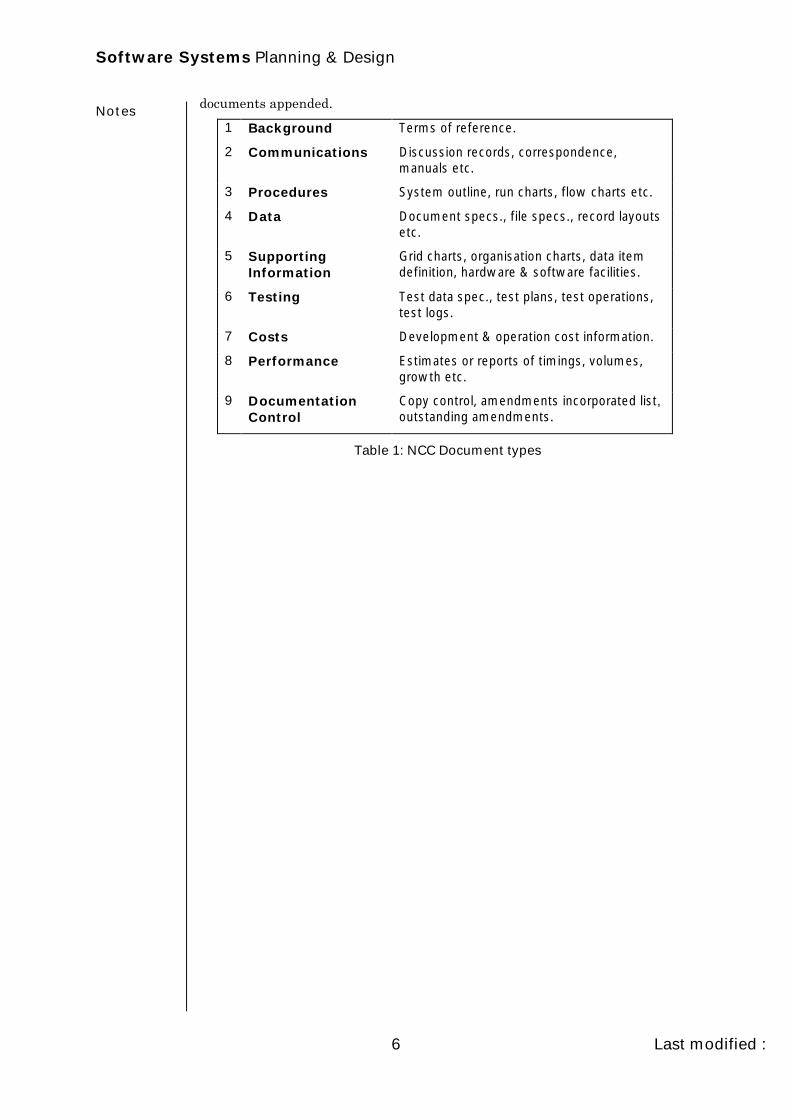
and was characterised by attempts to produce technical and user documentationusing standard forms and check lists. The underlying document categories areas shown in Table 1 and illustrated by the Poly Fleet Hire Case Study example
Software Systems Planning & Design
Last modified :
Notes
6
documents appended.
1 Background Terms of reference.
2 Communications Discussion records, correspondence,manuals etc.
3 Procedures System outline, run charts, flow charts etc.
4 Data Document specs., file specs., record layoutsetc.
5 SupportingInformation
Grid charts, organisation charts, data itemdefinition, hardware & software facilities.
6 Testing Test data spec., test plans, test operations,test logs.
7 Costs Development & operation cost information.
8 Performance Estimates or reports of timings, volumes,growth etc.
9 DocumentationControl
Copy control, amendments incorporated list,outstanding amendments.
Table 1: NCC Document types

Chapter 1 – Historical Development of SSDMs
16 April, 1999
Notes
7
The major criticisms of this approach were:
• Failure to meet the needs of management: Although systems developedby this approach often successfully deal with such operational processing aspayroll and the various accounting routines, middle management and topmanagement have been largely ignored by computer data processing. Thereis a growing awareness by managers that computers ought to be helping theorganisation to meet its corporate objectives.
• Unambitious systems design: Producing a computer system that mirrorsthe current manual system is bound to lead to unambitious systems whichmay not be as beneficial as more radical systems.
• Models of processes are unstable: The conventional methodologyattempts to improve the way that the processes in businesses are carriedout. However, businesses do change, and processes need to changefrequently to adapt to new circumstances in the business environment.Because computer systems model processes, they have to be modified orrewritten frequently. It could be said therefore that computer systems,which are ‘models’ of processes, are unstable because the real worldprocesses themselves are unstable.
• Output driven design leads to inflexibility: The outputs that thesystem is meant to produce are usually decided very early in thedevelopment process. Design is ‘output driven’ in that once the output isagreed, the inputs are decided and the processes to convert input to outputcan be designed. However, changes to required outputs are frequent andbecause the system has been designed from the outputs backwards, changesin outputs usually necessitate a very large change to the system design.
• User dissatisfaction: Sometimes systems are rejected as soon as they areimplemented, often because the user requires more flexibility than thecomputer system has been designed to give. Users have found it difficult tounderstand technical matters which are often given far more attention thanthe underlying business problems.
• Problems with documentation: Although claimed to be one of the majorbenefits of the NCC approach, it has been criticised for being too technical,too easy to leave until too late, too easy to forget altogether and too easy toforget to update.
• Incomplete systems: Exceptions are frequently ignored because they aretoo expensive, and often not diagnosed or simply forgotten.
• Application backlog: Some users literally have to wait for years for asystem to be implemented. Others simply do not bother asking.
• Maintenance workload: Keeping operational systems going whether theyhave been designed well or badly will nearly always take first placesometimes leading to ‘patches’ upon ‘patches’. The maintenance workload isin most cases an increasing one.

Software Systems Planning & Design
Last modified :
Notes
8
1.7. Exercises
1. From your own practical experience, describe the disadvantages of theconventional approach to systems development.
2. From the point of view of management, what are the major drawbacks of theconventional approach?
3. What major benefits can be attributed to the N.C.C. standards approach tosystems development?
4. In your opinion, are the criticisms given above fair? Explain.
5. Using the Poly Fleet Hire documents identify the car registration numberfield and comment on the implications of an increase in the length of thisfield.
6. To what extent are the criticisms of this method dependent upon its being amanual documentation approach and, hence, would be ameliorated in amachine implementation?

Chapter 2 – Jackson System Development
16 April, 1999
Notes
9
2. Jackson System Development
2.1. An Overview
2.1.1. Extension of JSP
Jackson System Development (JSD) was developed as a superset, or anenlargement of Jackson Structured Programming (JSP). Whereas JSP is amethod essentially for designing and developing single programs, JSD takes theprocess a stage further by allowing the designer to build complete computersystems of communicating sequential programs. JSD is significantly orientedtowards effective software production and hence its critics say it does notsufficiently address feasibility and cost justification.
2.1.2. Theoretical Foundations
JSD is founded on the principle that the development of a system shouldconsider the real world subject matter about which the system is to computeand produce information and should construct a formal model of that subjectmatter, before turning attention to the functional requirements of the system.The most relevant aspect of real world subject matter is when somethinghappens to it and it is this aspect of happening (or the occurrence of an action)which the system developer should be most interested in understanding whenstarting a development project.
2.1.3. Real World Modelling
JSD is ideal for developing systems in whose real world subject matter it isimportant to recognise the occurrence of actions within a time dimension.Control systems, embedded systems, data processing and information systemsall fall into this class. The central aspect of JSD is the modelling of the realworld and the use of the resultant model as the basis for later developmentstages.
2.1.4. Limitations
JSD requires that the problem have a time dimension. This implies that certainsystems (such as a census) cannot be modelled using JSD.
2.1.5. JSD and Maintainability
Jackson claims that it is easier to build maintainable systems using JSDbecause the initial model of the real world is a stable basis for development,being less likely to change than the functions subsequently added to it. Shouldadditional functionality be required then a model created using JSD is easier toadd to than a model based on hierarchical decomposition of functionalrequirements. This is because the initial JSD model does not consider thefunctional requirements.
2.1.6. JSD Stages
JSD identifies three phases which broadly relate to the system specification,

Software Systems Planning & Design
Last modified :
Notes
10
design and construction stages of the software lifecycle. These are:
1. The Modelling Phase;
2. The Network Phase;
3. The Implementation Phase.
The first of these, the modelling stage, comprises the main thrust of the methodand is the most widely used aspect of the method in industry.
2.2. Modelling Phase
In the modelling phase, the developer identifies those actions of interest in theapplication domain. An action is simply an instantaneous happening, such asthe arrival of a customer order or the point at which somebody’s account isopened. For each action, a list of data attributes can be defined. For example, thepurchase of a book would have the attributes, book title, author, price, etc.
The next step within the phase is to take each action and try to put it in timeorder, under a given entity name, so that each action relates to an entity.
2.2.1. The entity in JSD
An entity is something in the real world that performs actions on the system orsuffers actions from the system.
2.2.2. The Steps
1. From analysis notes, interviews and documentation draw up a list of actionswhich may be found in phrases, verbs and nouns.;
2. Describe actions with one or two sentences of English and list actionsattributes;
3. Allocate actions to entities;
4. Create preliminary action sequence in entity life histories;
5. Review entities to check: entity boundaries are correct, and no separate livesexist (marsupial entities);
6. Describe entity life histories as a model process with a process structurediagram (a process structure diagram follows the same conventions as forJSP);
7. Define entity attributes, the type and updating actions.
2.2.3. Documentary Output
1. Candidate list of actions and entities and reasons for any rejected items;
2. Final list of actions and entities;
3. Action descriptions and associated attributes;
4. An entity/action cross reference;
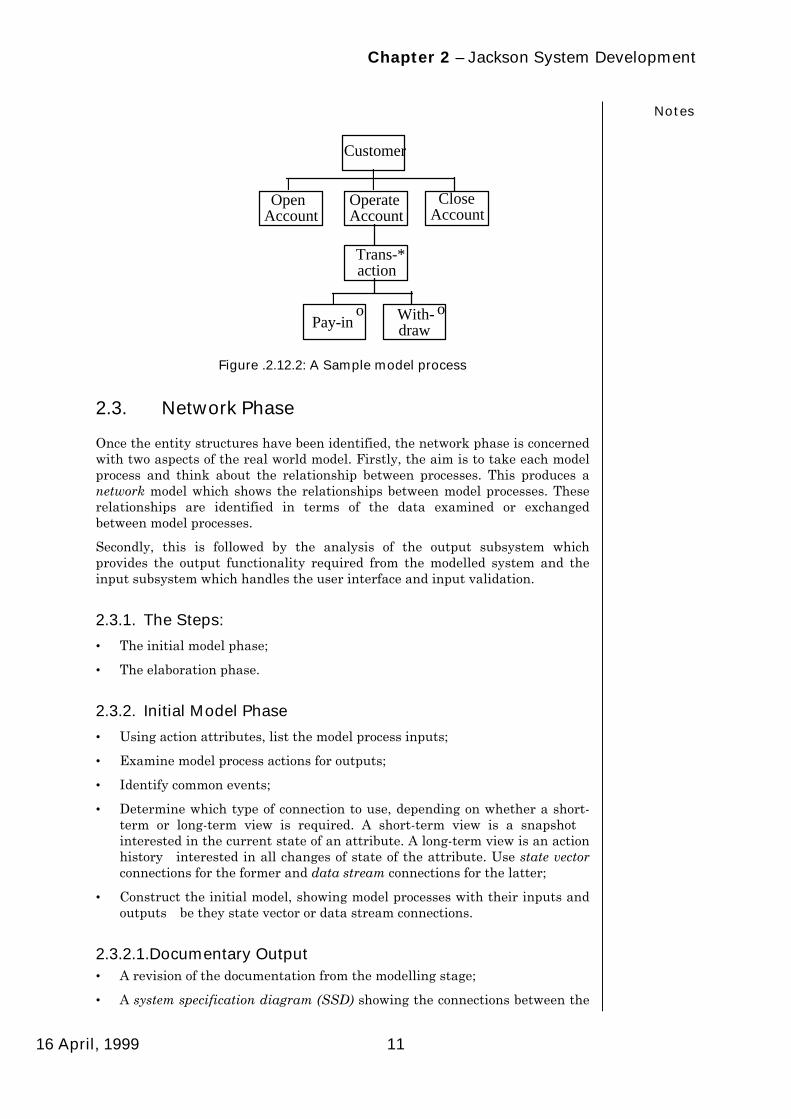
5. At least one process structure diagram for each entity. Figure 1-1 is anexample of a process structure diagram or model process for the entityCUSTOMER with each elementary component representing an action thecustomer performs;
6. The Structure Text (schematic logic).
Chapter 2 – Jackson System Development
16 April, 1999
Notes
11
Customer
Open Account
Operate Account
Close Account
Trans- action
Pay-in With- draw
*
o o
Figure .2.12.2: A Sample model process
2.3. Network Phase
Once the entity structures have been identified, the network phase is concernedwith two aspects of the real world model. Firstly, the aim is to take each modelprocess and think about the relationship between processes. This produces anetwork model which shows the relationships between model processes. Theserelationships are identified in terms of the data examined or exchangedbetween model processes.
Secondly, this is followed by the analysis of the output subsystem whichprovides the output functionality required from the modelled system and theinput subsystem which handles the user interface and input validation.
2.3.1. The Steps:
• The initial model phase;
• The elaboration phase.
2.3.2. Initial Model Phase
• Using action attributes, list the model process inputs;
• Examine model process actions for outputs;
• Identify common events;
• Determine which type of connection to use, depending on whether a short-term or long-term view is required. A short-term view is a snapshot—interested in the current state of an attribute. A long-term view is an actionhistory—interested in all changes of state of the attribute. Use state vectorconnections for the former and data stream connections for the latter;
• Construct the initial model, showing model processes with their inputs andoutputs—be they state vector or data stream connections.
2.3.2.1. Documentary Output• A revision of the documentation from the modelling stage;
• A system specification diagram (SSD) showing the connections between the

Software Systems Planning & Design
Last modified :
Notes
12
external reality and the realised model.
2.3.3. Elaboration Phase:
The elaboration phase adds the functionality required from the system to theSSD. Once we have designed the majority of our system we then add the newfunctionality to cover the user requirements. This new functionality is a set ofnew processes or amendments to existing model processes to incorporate thefunctionality. These new processes are known as functions or functionalprocesses. There are four types of functional process: embedded functions, outputfunctions, interactive functions and filter functions.
Embedded Functions: These alter an existing model process. If no structuralchange is required then they may be embedded into an existing model process.They usually consist of the addition of variables, elementary operations and soforth to an existing model process. Small sub-trees may be added provided thestructural integrity of the model process is maintained. Any number of newvariables and elementary operations may be added but nothing must be done tochange the time ordering of the model processes actions. They may be connectedto the rest of the SSD by either data stream or state vector connection.
Output Functions: These are similar to embedded functions in that they arepresent to fulfil some other function or user requirement. They are modelled asseparate processes. Consider the embedded function which, by the addition ofsome actions, sends data for printing or screen output. Obviously there needs tobe a report formatting process. The output function receives the raw data fromthe embedded function and then formats it for output. Output processes mustfrequently inspect the state vector of their connected processes and are usually ofa report writing or query screen nature. Since most state vectors are inimplementation terms files many database query programs are in effect outputfunctions. Since most output functions are usually of a query nature andtherefore stimulated by user demand rather than at a given time, state vectorsare the obvious form of connection. When the user demands to see something itis the current state that is required, not what happens to be next in the buffer ofa data stream. However, data streams may be used if the query is of amandatory monitor nature. Output functions usually have to inspect the statevectors of many processes and usually in a strict order, query functions tend tobe complex.
Interactive Functions: This type of function is also an individual process,usually because of the number of tasks involved in the type of user requirementwhich leads to the need for the function. They are the most complex form offunction. Interactive functions are so called because they interact with thesystem and/or user; they gather information from the user and/or other systems,process it and feed it back into the system. The connections to the rest of thesystem are usually data streams and usually involve many new and changedactions being embedded into existing processes. Data streams are used ratherthan state vectors because the processing of data is usually in some mandatorysequence.
Because of the complex nature of interactive functions they are necessarilylarge, forming complete sub-systems in their own right. Although they carry outthe requirements of a complex interactive user function (either with the systemor the user) they should be built as if they are systems i.e. we use most, if not all,of the stages of the development cycle, starting with the requirements capturestage.
Filter Functions: These are used to filter out invalid data from or within thesystem. Filter function literally filter input data to the processes connected tothe outside world or other sources of potentially invalid data. Filter functions

Chapter 2 – Jackson System Development
16 April, 1999
Notes
13
are always connected to other processes via data streams which enforce arequired closely coupled relationship. Filter functions reduce the complexity ifthe model processes by modelling most of the bad data possibilities.
Timing Constraints: There are a number of ways that timing constraints canbe added to the model. the analysis of the system will have identified thoseprocesses which need constraint. For example, we need to be able to schedulewhen a report is required; we may need to synchronise groups of processes andso on. If more than one data stream is inputting into a process and the order inwhich data arrives is not important then the data streams can be rough merged.However, data may be required more quickly from one data stream thananother, in which case some control needs to be exerted.
The overall objective of adding time constraints to the system is to bring aboutsynchronisation between processes and within processes. At the network levelsynchronisation effectively makes an otherwise concurrent system behavesequentially. It is worth remembering that individual processes are designed asessentially sequential whilst the network model is primarily concurrent.Therefore, the sequential flow of control is theoretically uninhibited, the onlyconstraints being the speed of the processor (which is an implementationproblem), and the availability of data external to the process.
Consider a process that is processing input dataóeventually it must producesome output. When does it produce this output? At a given time? how muchdata must it process first? Which input data is vital, which is optional? We couldgo on. The most critical aspect of these varieties is time. Time is entered into thesystem like any other piece of data—but always as a data stream—this isknown as a time grain marker (TGM). TGMs are sent to a process as a separatespecialised data stream and are read as input records. The process looks fortheir arrival before some action is allowed to occur. A frequent use of TGMs isthe control of rough merged data streams. Rough merged data streams exhibitno favouritism to any of the constituent data streams, and if one is writingfaster than the other then it will tend to get more attention—TGMs can controlthis state of affairs.
Documentary Output:
• A SSD showing the extra functional processes, their connections with themodel processes and their connections with each other. Figure 2.3 is asample SSD showing the process CUSTOMER connected to the processACCOUNT by a data stream connection; and the process BALANCE REPORTconnected to ACCOUNT by a state vector
Customer AccountDS
Balance Report
SV
Figure 2.3: A Sample System Specification Diagram
• Elaboration of the model process documentation (structure diagram with

Software Systems Planning & Design
Last modified :
Notes
14
operations allocated and list of operations) to show extra local variables andcalculations used for embedded output or to hold information for state vectorinspection;
• The structure and text of the extra functional processes;
• A concise statement of access paths on state vectors defined by functionalprocesses.
2.4. Implementation Phase
In this phase the SSD, which is viewed as a network of concurrentlycommunicating processes, is transformed into a sequential design that may beimplemented on one or more processors. This process is known as scheduling.this is followed by further detailed design and coding.
The steps of this stage are:
• Divide the SSD into scheduling groups according to system requirements ofdistributed processing, hardware and user interface needs;
• Add a scheduler process for each scheduling group;
• Start with system inputs and invert input processes as subprocesses of hescheduler;
• Following data stream connections in the SSD, invert the nearestneighbours to input processes as the next subprocess level and continueuntil output is reached
• Add buffers for fixed merges and show access paths to processes;
• Add state vector files and show access paths to processes;
• Convert process specifications to inverted form by changing writes and readsto calls and exit-programs;
• Assign elementary operations and conditions to program components;
• Ad further details to elementary operations and conditions in pseudo code oras statements in the target language.
2.4.1. Documentary Output:
• A set of informal timing constraints on the implementation;
• Elaboration of process structure diagrams;
• A system implementation diagram (SID).

Chapter 2 – Jackson System Development
16 April, 1999
Notes
15
2.5. JSD Notation
Fixed Merge
Rough Merge
Clock Clock Process
Connection 1: Many
Connection 1:1
TGM Time Grain Marker
DS Data Stream
SV State Vector
Customer Entity/Process
2.6. Exercises
1. Why might JSD be called a method involving composition rather than themore usual decomposition?
2. Why might it be better to expend a good deal of time in the modelling phaserather than attempt to establish system functions early on?
3. Why do we say that JSD is a superset of JSP, rather than a front end to it?
4. What do you understand by the notion of time ordered entities?

Software Systems Planning & Design
Last modified :
Notes
16

Chapter 3 – JSD Modelling — Underlying Ideas
16 April, 1999
Notes
17
3. JSD Modelling — UnderlyingIdeas
3.1.1. The Scope of JSD
Jackson system Development (JSD) can be used to develop systems in whosereal world subject matter it is important to recognise the occurrence of eventswithin a time dimension. Control systems, embedded systems, data processingand information systems all fall within this category. A central aspect of JSD isthe modelling of the real world and the use of the resultant model as the basisfor later development stages.
3.1.2. Towards More Maintainable Systems
"The JSD insistence on starting development by explicitly modelling the realworld ensures that the system user’s view of reality is properly embodied in thespecification and, eventually, in the structure of the system itself. The developedsystem can then be expected to allow easy enhancement for functions consistentwith this view of reality" 1
Jackson claims that it is easier to build maintainable systems using JSDbecause the model of the real world is a stable basis for development, being lesslikely to change that the functions built upon it. That is to say that customersand their actions rarely change, but the way in which these actions areperformed changes more frequently. The system developer and the user canmore easily agree on a set of system functions to be supported either in originaldevelopment or later maintenance because the system embodies the model andthe model defines a set of possible functions. By contrast, a system which is notbased on an explicit model of reality means that new functions may bearbitrarily cheap or expensive to implement.
3.2. Modelling the Real World
3.2.1. Modelling Before Functions
Traditionally system development starts by considering the functionalrequirements of the proposed system; often each major system function isorganised in a hierarchy of processes connected by data flows. The developmentof systems using JSD starts by building a model of the real world whichprovides the subject matter of the system. the model is a realisation of anabstract description of the real world—a kind of simulation. The function of thesystem are added to the model and the systems can produce a display of thestate of the model or the occurrences of certain events which can be used forinformation or control purposes.
Consider the following example:
‘A car hire firm has recently installed a terminal which is used torecord the dates when cars are hired out and returned. When acar is taken out the registration number is keyed in with a prefix‘[‘ to indicate ‘taken out’ and the date (in the form of number of
1M.A. Jackson, 'System Development', Prentice-Hall, 1983, pp. 11.

Software Systems Planning & Design
Last modified :
Notes
18
days since system commission date) is automatically added.When a car is returned the registration number is keyed in withthe prefix ‘]’ and the date is again automatically added. Themanager wants the following information from the system: thenumber of separate hire contracts and the average number ofdays fro which a car is on hire’
The functions of such a simple management reporting system are (ignoring thepossible argument that data acquisition is itself a function):
i. Compute the information;
ii. Output it in a simple form.
The computation consists of three parts:
i. Count the number of separate hire contracts (i.e. count the transactionsbeginning with ‘[‘);
ii. Total the number of days when cars are hired;
iii. Compute the average.
This could be represented in structured English as:
BEGIN initialise number of contracts and total days = zero; get first transaction; WHILE not end of transactions DO IF car taken out (code = ‘[‘) THEN number of contracts := number of contracts + 1; total days := total days—taken out date; ELSE total days + brought in date; get next transaction; Print number of contracts; IF number of contracts not = zero THEN print average duration (total days / number of contracts);END
Examine the above solution to see if it works. Note, it is rather simple minded inthe sense that the management information will only be produced when alltransaction data are available and all cars are returned.
i. Now specify the changes that would be required if the manager now wanteda further report giving the longest period of hire.
ii. Now specify the changes that would be required if the manager wanted twoseparate reports one for hire periods of less than a week and one for a weekor longer.
iii. What changes would be required to allow the system to be run at any time(i.e. when there are cars outstanding)?
These changes are difficult without a complete rewrite because the systemreflects the computer expert’s interests in algorithms to compute efficiently totalelapsed time and does not consider the user’s main concern—the time forindividual contract hire periods. The real world of the manger is about contractsand their duration; a model of this real world would have revealed this andimplied possible functions some of which would have been realised when themanager made his information requests which were all about contract hireperiods.
Using JSD we would model a contract and ask questions about what happens toit. We then obtain events, apply time ordering and use the results as a model

Chapter 3 – JSD Modelling — Underlying Ideas
16 April, 1999
Notes
19
process upon which to build possible functions.
3.2.2. Simulation of Objects in the Real World
Many software systems can be usefully regarded as simulation of their realworld subject matter. embodied in such a system is a discrete simulation of thebehaviour of objects in the real world. The information and control objects of thesystem are in fact derived from the internal behaviour and state of thesimulation but are interpreted as having validity in the real world. Thus we caninspect the state of the model to gain information.
Consider the traditional payroll system. The real world for this system isemployees of the organisation, the work they do, the holidays they take, theirarrival at the place of work and their departure from it, their promotions, theirincreasing age as the years go by, and so on. The essential outputs of the systemare payslips and pay cheques, management reports about total pay, amount ofovertime worked, perhaps also about productivity, and taxation and returns tosuch bodies as the Inland Revenue.
3.2.3. The Validity of the Outputs
The validity of the outputs is only to the extent that the systems is running avalid simulation of the real world. If there are no simulated apprentices in thesystem, then there should not be any output in respect of apprentices.conversely, when a real employee goes on holiday then a simulated employeealso goes on simulated holiday in the computer system. In this case we areentitled to count the occurrences of the simulated holidays and draw inferencesabout real world holidays. Note here the similarity in concept to that of theobject oriented paradigm where real world objects have their lives modelled andtraced by system objects.
3.3. The Need for a High Quality Model
3.3.1. Accuracy for the Intended Purpose
The quality and value of an information or control system will depend veryheavily on the accuracy of the simulation for the intended purposes. If wesimulate the hours spent in the work place by events such as ‘Jones has spent 6hours at work today’, we will be able to draw correct inferences about the totalhours spent provided we wait until the end of the day. However, we will not beable to draw correct inferences during the working day about who is or who isnot presently at work unless we simulate the arrivals and departures of theemployees as they happen. Then, of course, we could inspect the state of the‘Jones’ process and ascertain whether he is at work, and if so how long he hasbeen there.
3.3.2. The Model Must be Understood by Users
The model must also be understood by the people who are to use its outputs. Adisparity between the understanding of the users of the systems and the systembuilders will lead to a loss of value in the information produced. Hence, thesimulation must reflect the real world as the users of the information systemsee and understand it. In JSD communication between the developer and theuser is improved because the developer is seem to be seeking knowledge fromthe user’s point of view. A description of what the user already knows precededinvention of functional or technical novelties i.e. clever ways of simulating

Software Systems Planning & Design
Last modified :
Notes
20
events in the real world. However, we must be aware that different system userswill have different perceptions of the system. These differences being causedboth by their differing viewpoints and personal subjectivity—these differingviews are known as roles.
3.3.3. Models of the Real World
It is of the up most importance in building software systems of the kind we areconsidering here to take the greatest care in describing the real world and themodel or simulation that will be built on the basis of that description. JSDconcentrates heavily on modelling in the same sense that an architectural modelis a model of a real building, or a map is a model of a real terrain. This is notmodelling the system itself, or modelling some existing manual or mechanisedsystem that is to be replaced, or modelling the behaviour of the system;seventual users, but modelling the real world, the subject matter about which thesystem computes, and in the context of which its outputs are to be interpreted.
3.3.4. Careful Modelling
The model of the real world must be made in the most careful way using thedescriptive languages and concepts that are best suited to the subject matterbecause this model will furnish the basis of the system’s ability to serve itsultimate purpose, the production of useful and valid information and controloutputs.
3.4. Data Modelling
3.4.1. The Entity Relationship Model
One of the sets of languages and concepts often used for modelling the real worldis that offered by some form of data modelling such as the entity relationshipmodel. Here, in essence we describe the real world by describing the entities tobe found there, their attributes and the relationships which exist among them.
For example, if we are concerned with a world in which we engage inconstruction projects using items obtained from various suppliers, we mightdefine a relation SIP (Supplier—Item—Project):
SIP: SUPPLIER ITEM PROJECTS123456 I678 P543210S123456 I789 P543210S123456 I678 P379106 .. .. .. .. .. ..
A tuple in the relation SIP such as (S123456, I678, P543210) means thatsupplier S123456 is-a-supplier of item I678 to project P543210.
What exactly does is-a-supplier mean? If a catastrophe occurs in project P, andwe want to warn all of the project suppliers that we might be suing then fordamages, should we warn every supplier who has a tuple in this relation inwhich the column has the value P? (Why might this not be valid?) If the designof the project’s product is changed, and we want to request specification changesfrom suppliers of affected items, which suppliers must be told? To answer theseand other similar questions we would naturally discuss the meaning of therelation in terms of events. We might say that a supplier S is-a-supplier of item Ifor project P if S has been put on the approved list for I for project P and has notbeen removed from the list; or if S has delivered at least one batch of item I to
Chapter 3 – JSD Modelling — Underlying Ideas
16 April, 1999
Notes
21
project P; or if item I has been ordered from supplier S on at least one occasionfor project P, even if it has not yet been delivered. From this it can be seen howcrucial time-ordering is to interpretation.
3.4.2. Real world events
The natural way to understand the meaning of the relation is to consider thereal world events that affect it, and the natural way to explain the relation is interms of those events. It follows that in this example the occurrences of eventsare more basic that the existence of the relation, and that our modelling shouldstart from the events. This will be true generally in systems whose real worldsexhibit the occurrence of events within a time-ordering: where there are events,where there is a time dimension, we need to start there.
3.5. Events in JSD
A JSD event is thought of as atomic: we do not decompose events into sub-events and we think of them as being instantaneous, occurring at a particularmoment in time. This is, of course, an abstraction: our description of the realworld will, necessarily, ignore some aspects and details of reality. This iscomparable to the logical data structures used in JSP which ignore detail not ofdirect interest to the problem. To use a simple and well known illustration, thelending of a nook by a lending library may be described in a JSD model as anevent; but the reality is more complex, because there is a whole microcosmichistory from the moment the borrower takes the cook from the shelf and beginsto browse in order to decide whether to borrow it up to the time the book isplaced in the library’s checkout desk and then, eventually, handed to theborrower to take home. we abstract from these complexities at a single point intime.
3.5.1. Event Attributes
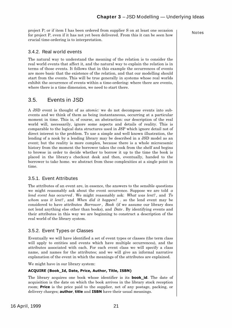
The attributes of an event are, in essence, the answers to the sensible questionswe might reasonably ask about the event occurrence. Suppose we are told ‘alend event has occurred’. We might reasonably ask: ‘What was lent?’, and ‘Towhom was it lent?’, and ‘When did it happen?’ . so the lend event may beconsidered to have attributes ‘Borrower’, ‘Book’ (if we assume our library doesnot lend anything else other than books), and ‘Date’. By identifying events andtheir attributes in this way we are beginning to construct a description of thereal world of the library system.
3.5.2. Event Types or Classes
Eventually we will have identified a set of event types or classes (the term classwill apply to entities and events which have multiple occurrences), and theattributes associated with each. For each event class we will specify a classname, and names for the attributes; and we will give an informal narrativeexplanation of the event in which the meanings of the attributes are explained.
We might have in our library system:
ACQUIRE (Book_Id, Date, Price, Author, Title, ISBN)
The library acquires one book whose identifier is its book_id. The date ofacquisition is the date on which the book arrives in the library stock receptionroom; Price is the price paid to the supplier, net of any postage, packing, ordelivery charges; author, title and ISBN have their usual meanings.

Software Systems Planning & Design
Last modified :
Notes
22
CATALOGUE (Book_Id, Date, Class)
The librarian enters one book in the library catalogue, date is the date of entryinto the catalogue; class is the Dewey Decimal number plus the first 3characters of the author’s name; Book_Id is the identifier of the book entered inthe catalogue.
LEND (Book_Id, Member_Id, Resvn_Id, Date)
A book, whose identifier is Book_Id, is lent to the member whose membershipnumber us Member_Id; date is the date of removal of the book from thelibrary’s premises; Resvn_Id is the identifier of the relevant reservation if thecook is borrowed against a previous reservation.
There may be many other definitions of event classes. Naturally, it will beappropriate to hold these definitions in some kind of development database(such as Speedbuilder q.v).
3.5.3. The Importance of Events
Three points need to be made about the importance of events in JSD:
1. Our initial description of the real world is in terms of ‘what happens’. Webegin by describing the classes of events of interest. In the kind of real worldwe are talking about—and most real worlds for information and controlsystems are of this kind—this is the most natural and direct description togive;
2. By listing event classes in this way, we are beginning to define the scope ofthe eventual system: the system will, in principle, be able to produce anyoutputs that can be deduced from knowledge of the occurrences of the eventsof the defined kinds and no other outputs;
3. We give an informal narrative description of each event class to provide thenecessary link between the formal systems specification we are making andthe real world itself as understood and experienced by our users andcustomers. such a link between formal and informal is always needed unlessthe real world is itself a formal object or system.
3.6. Objects, Entities and Event Orderings
3.6.1. Choosing Entity (or Object) Classes
A description of the real world in terms of events only is likely to be veryincomplete. Most often we will also want to describe the objects or entities thatpersist over time and that take part in the events: in the library we will want todescribe at least books and members and perhaps other objects or entities too. Inmany cases we can recognise quite easily some or even all of the entity classesthat we need to describe; but we will often find ourselves in doubt whether toinclude some particular candidate in the list of entity or object classes. This isarguably the hardest part of JSD. For that reason, and also because it is anilluminating exercise, we will approach the problem of choosing entity or objectclasses strictly on the basis of the set of event classes we have alreadyconstructed.
3.6.2. Event History
If we consider the set of all possible ‘traces’ of events in the real world (where atrace is an ordered history of particular event occurrences), we may ask whether

Chapter 3 – JSD Modelling — Underlying Ideas
16 April, 1999
Notes
23
any regularities of ordering can be observed to be true of all traces. In particularwe may ask this question about sets of events that share a particular attributevalue: for example, about the set of events that all have the Book_Id valueB4567, or the set of events that all have the Member_Id value M123. Whenconsidering such a set we will often be led to observe quite definite regularitiesof ordering: for example, that book B4567 must necessarily be ACQUIREDbefore it is LENT, and that LEND and RETURN events must alternate, and thatvarious other ordering regularities also hold. We can express such regularitiesas ‘time-orderings of events’, for which a suitable notation is available in thetextural and diagrammatic forms of regular expressions used in JSP programdesign.
3.6.3. Entity Diagrams
Figure 3.1 shows a book in our imaginary library: it expresses the time-orderings that are true in the particular real world are considering here, and weare assuming that our user (who knows all about the world of the library), hasgiven us the information on which the diagram is based and has confirmed thatwe have used that information correctly. N.b., Observe that the diagrammingrules for JSP apply equally to JSD
Book
Acquire Catalogue Useful Life
Loan
Lend Return
*
Sell
Figure 3.1: An entity structure diagram
3.6.4. Identifying Entities
The fact that this is a time-ordering in the real world is a direct indication thatbooks must be regarded as entities in our real world description. Somethingabout the real world constrains LEND and RETURN events for a given Book_Idvalue to alternate: that something is, of course, the nature of the LEND andRETURN events and the physical nature of books. Books are entities that havestates and these states change when books take part in events. Consider, bycontrast, the absence of time-ordering for a particular value of the processattribute. We will not find that ACQUIRE events at price X must precede, orfollow, or alternate with, SELL events at price X: there is no constraint at all onthe orderings of events with the attribute price = X. We may confidently assert,therefore, that in the world of our library, price is not an entity class, and thatwe will not wish to speak of price objects or price entities. (Of course, we aremaking sensible assumptions for purposes of explanation; there is no reason

Software Systems Planning & Design
Last modified :
Notes
24
why in some other real world, prices should not be entities or objects and havesignificant time-ordering2 ).
3.7. Entity Attributes
3.7.1. Entity States
Having identified, perhaps, books, members, and reservations as significantentity classes in our tiny library world we can turn our attention to describingtheir states. The state of an entity is recorded, essentially, in the values of itsentity record fields or, in object-oriented parlance, its instance variables. As afirst step towards defining the system’s information outputs we may askourselves what information we want each class of entity to store in its entitystate. This information is essentially just a summary record of the entity’s eventhistory; we record it because we do not want to record all event occurrences overthe whole life of the system, and we do not want to be forced to analyse acomplete event history to answer every request for information.
3.7.2. Specifying Entity Attributes
In JSD we specify entity attributes and their meanings in terms of the events wehave already specified in the context of the time-orderings we have alreadygiven for the entities. Suppose, for example, we wish to specify an attribute ofbook that we may call ‘loan-count’: it is simply a count of the number of timesthe book has been lent. We would specify ‘loan-count’ by saying how its value isdetermined by the events in the life of a book: it is zero when the book is initiallyACQUIRED and its increment by one on each LEND event. Or should it beincremented by one on each RETURN event instead? The decision is one that weand our user may take freely in the light of the expected use to which thisinformation will be put; but however the decision is made we will have anunambiguous and clearly agreed specification of what ‘loan-count’ means.
A slightly more subtle example of the same point arises with an attribute in-the-library. We want to be able to ask of any book ‘is it in the library?’ and we needto be sure that we and the users of the system have the same understanding ofwhat ‘in-the-library’ means. We achieve this certainty by specifying the value of‘in-the-library’ at every point in the history of a book and so eliminate thepossibility of misunderstanding altogether. An example of a possiblemisunderstanding might be: Is a book ‘in-the-library’ when it is out on loan?
3.8. Exercises
1. Why is it claimed that JSD facilitates systems maintenance? If the claim istrue, what is its significance?
2. How would you explain the statement ‘a JSD model is a realisation of anabstract description of the real world’?
3. Use a simple (?!) payroll system to show how validity of the systems outputsis crucially affected by the quality of the model or simulation of the realworld.
2 In computerised stock market trading a 'stop-loss' event is triggered by a price event.

Chapter 3 – JSD Modelling — Underlying Ideas
16 April, 1999
Notes
25
4. If the system’s developer and the user have different understandings of thecomputer system’s behaviour any information produced is suspect. Is thisstatement true? Does JSD do anything to help overcome this problem?
5. In what sense are JSD models models of the real world? With what type ofmodels should they not be confused?
6. Explain why the entity relationship model may not be ideal in some cases.
7. What is a JSD event?
8. How might we identify event attributes?
9. How might we advantageously define events?
10. How important is it to start a requirements analysis by considering theevents of the system?
11. What will a time-ordering of events allow us to produce?
12. How might a JSD entity be recognised?
13. What is an entity attribute? Give some examples.
14. How might we clarify the definition of an entity attribute?

Software Systems Planning & Design
Last modified :
Notes
26