1 Half Inch Cover and Spine - plans.shshotelus.net Hotel Projects/Home2 Suites - Flowood MS... ·...
65
Transcript of 1 Half Inch Cover and Spine - plans.shshotelus.net Hotel Projects/Home2 Suites - Flowood MS... ·...


Detail Bill of Material Page 1 of 1
Project Name: Home 2 Flowood Negotiation No: MH880916X6K3 General Order No:
Alternate No: 0002
Item No. Qty Product Description 1 Switchboards Pow-R-Line CSwitchboard, Front Access/ Front and Rear Align,
Type 1, 208Y/120V 3-Phase 4-Wire, 3000 Aluminum, Minimum Interrupting Rating: 100kA, Bus Bracing Rating: 100kA
Designation MDP
Qty List of Materials 1 Pow-R-Line C 1 Service Entrance Label 2 Structure Bus Bracing - 100 kA 1 3000 Amp AL Main Structure 31 Nameplate 1 Digitrip RMS520 LSI - Standard 1 Vertical Isol. Barrier (Service Entrance) 1 Switchboard ID Nameplate 1 3000 Amp AL Distribution Structure 21 Mechanical Terminals: (1) #6-300 kcmil 30 Thermal Mag Trip - Standard 2 Shunt Trip (48-127Vac) 1 3000A 3P Magnum SB Brkr SBS-C30 [Fixed-Manual], Trip 3000 A,
RMS520 LSI, (8) 3/0-750 kcmil, Mechanical, Bottom
16 225A 3P [EDH 225A Frame], Trip 225 A, Thermal Mag, (1) #6-300 kcmil, Mechanical
4 225A 3P [EDH 225A Frame], Trip 225 A, Thermal Mag, (1) #4-4/0, Mechanical
5 200A 3P [EDH 225A Frame], Trip 200 A, Thermal Mag, (1) #6-300 kcmil, Mechanical
3 100A 3P [HFD 225A Frame], Trip 100 A, Thermal Mag, (1) #14-1/0, Mechanical
1 300A 3P [HKD 400A Frame], Trip 300 A, Thermal Mag, (1) 250-500 kcmil, Mechanical
1 300A 3P [HKD 400A Frame], Trip 300 A, Thermal Mag, (2) 2/0-250 kcmil, Mechanical
Eaton Selling Policy None applies.
All orders must be released for manufacture within 90 days of date of order entry. If approval drawings are required, drawings must be returned
approved for release within 60 days of mailing. If drawings are not returned accordingly, and/or if shipment is delayed for any reason, the price of the
order will increase by 1.0% per month or fraction there of for the time the shipment is delayed.

Switchboard General InformationPow-R-Line C - SpecificationsQuantity: 1Alignment: Front Access/ Front and Rear AlignService: 208Y/120V 3-Phase 4-Wire Minimum Interrupt Rating: 100 kA
Bus SpecificationsBus Amps: 3000 Bus Bracing Rating: 100kANeutral Amps: 3000Bus Material: Aluminum Heat TestGround Bus Material: Aluminum .25 X 3.0 Ground Bus Bolted To Frame, (1) #6-350 kcmil Ground Lug
Incoming InformationIncoming Entry: Bottom Incoming Location: LeftIncoming Qty & Size: Terminals, Mechanical, (8) 3/0-750 kcmil, Bottom
Structure SpecificationsService EntranceEnclosure Type: Type 1Nameplates: Mastic - White with Black letters
Enclosure propertiesStruct # Description/Modifications1 Bottom incoming main device (Incoming Main Device/MLO Section)
Vertical isolating barrier2 50x chassis mounted feeders (Feeder Structure)
NEG-ALT Number
PREPARED BY DATE
APPROVED BY DATE
VERSION
REVISION DWG SIZE
JOB NAME
DESIGNATION
TYPE
G.O.
DRAWING TYPE
ITEM SHEET
The information on this document is created by Eaton Corporation. It is disclosed in confidence and it is only to be used for the purpose in which it is supplied.
MH880916X6K3-0002
TROY VANHOESEN 1/18/2017
8.0.14.0
0 DwgA
Eaton SumterSCHome 2 FlowoodMDP
Switchboards CustAppr
1 of 6

1Front View
Power Flow
Floor Plan
StructDepthWidth
3036
2 *
Total of 2 Structures, Total Weight of 2064 Weight-Lbs.Total of 2 Structures, Total Width of 81 Inches
3045
See 1A32043 ForFloor Plan Detail
Top/BottomCable Exit
29 30
27 28
25 26
23 24
21 22
19 20
17 18
15 16
13 14
11 12
9 10
7 8
5 6
3 4
1 2
Rear
24.00
30
2.50
3.00
12.00
39
2.50
3.00
Structure 1 2Ship-InchesShip-MM
81.002057
Wdth-InchesWdth-MM
36.00 45.00914 1143
Depth(Inner)-In.Depth(Inner)-MM
30.00 30.00762 762
Depth(Outer)-In.Depth(Outer)-MM
30.00 30.00762 762
Height-InchesHeight-MM
90.00 90.002286 2286
Weight-Lbs.(Est.)Weight-Kg.(Est.)
800 1264362 573
NEG-ALT Number
PREPARED BY DATE
APPROVED BY DATE
VERSION
REVISION DWG SIZE
JOB NAME
DESIGNATION
TYPE
G.O.
DRAWING TYPE
ITEM SHEET
The information on this document is created by Eaton Corporation. It is disclosed in confidence and it is only to be used for the purpose in which it is supplied.
MH880916X6K3-0002
TROY VANHOESEN 1/18/2017
8.0.14.0
0 DwgA
Eaton SumterSCHome 2 FlowoodMDP
Switchboards CustAppr
2 of 6

Switchboard Units InformationStr# Unit Description/Modifications Nameplate
1 MDP208Y/120V 3PH 4W3000A 100K AIC
Main Breaker - Ind Mtd-3000A 3P Magnum SB Brkr SBS-C30 [Fixed-Manual], Trip 3000A.RMS520 LSI, 100 % ratedTerminals, Mechanical, (8) 3/0-750 kcmil, Bottom
MAIN BREAKER
21 Feeder Breaker - Chassis Mtd-300A 3P [HKD 400A Frame], Trip 300A.Thermal Mag
Terminals, Mechanical, (1) 250-500 kcmilPANEL HAC
Neutral Terminal, (1) #4-500 kcmil
2 Feeder Breaker - Chassis Mtd-300A 3P [HKD 400A Frame], Trip 300A.Thermal MagTerminals, Mechanical, (2) 2/0-250 kcmil
PANEL RF
Neutral Terminal, (2) #6-350 kcmil
3 Feeder Breaker - Chassis Mtd-100A 3P [HFD 225A Frame], Trip 100A.Thermal MagTerminals, Mechanical, (1) #14-1/0
PANEL PL
Neutral Terminal, (1) #14-1/0
4 Feeder Breaker - Chassis Mtd-100A 3P [HFD 225A Frame], Trip 100A.Thermal MagTerminals, Mechanical, (1) #14-1/0
SPARE
Neutral Terminal, (1) #14-1/0
5 Feeder Breaker - Chassis Mtd-200A 3P [EDH 225A Frame], Trip 200A.Thermal MagTerminals, Mechanical, (1) #6-300 kcmil
PANEL OL
Neutral Terminal, (1) #6-350 kcmil
6 Feeder Breaker - Chassis Mtd-100A 3P [HFD 225A Frame], Trip 100A.Thermal MagTerminals, Mechanical, (1) #14-1/0
SPARE
Neutral Terminal, (1) #14-1/0
7 Feeder Breaker - Chassis Mtd-200A 3P [EDH 225A Frame], Trip 200A.Thermal MagTerminals, Mechanical, (1) #6-300 kcmil
PANEL CA
Neutral Terminal, (1) #6-350 kcmil
8 Feeder Breaker - Chassis Mtd-200A 3P [EDH 225A Frame], Trip 200A.Thermal MagTerminals, Mechanical, (1) #6-300 kcmil
PANEL LDY
NEG-ALT Number
PREPARED BY DATE
APPROVED BY DATE
VERSION
REVISION DWG SIZE
JOB NAME
DESIGNATION
TYPE
G.O.
DRAWING TYPE
ITEM SHEET
The information on this document is created by Eaton Corporation. It is disclosed in confidence and it is only to be used for the purpose in which it is supplied.
MH880916X6K3-0002
TROY VANHOESEN 1/18/2017
8.0.14.0
0 DwgA
Eaton SumterSCHome 2 FlowoodMDP
Switchboards CustAppr
3 of 6

Neutral Terminal, (1) #6-350 kcmil
9 Feeder Breaker - Chassis Mtd-200A 3P [EDH 225A Frame], Trip 200A.Thermal MagTerminals, Mechanical, (1) #6-300 kcmil
PANEL CB
Neutral Terminal, (1) #6-350 kcmil
10 Feeder Breaker - Chassis Mtd-200A 3P [EDH 225A Frame], Trip 200A.Thermal MagTerminals, Mechanical, (1) #6-300 kcmil
PANEL K
Neutral Terminal, (1) #6-350 kcmil
11 Feeder Breaker - Chassis Mtd-225A 3P [EDH 225A Frame], Trip 225A.Thermal MagTerminals, Mechanical, (1) #4-4/0
ELEVATOR #1
Shunt Trip: 48-127VacNeutral Terminal, (1) #6-350 kcmil
12 Feeder Breaker - Chassis Mtd-225A 3P [EDH 225A Frame], Trip 225A.Thermal MagTerminals, Mechanical, (1) #4-4/0
ELEVATOR #2
Shunt Trip: 48-127VacNeutral Terminal, (1) #6-350 kcmil
13 Feeder Breaker - Chassis Mtd-225A 3P [EDH 225A Frame], Trip 225A.Thermal MagTerminals, Mechanical, (1) #4-4/0
PANEL 1A
Neutral Terminal, (1) #6-350 kcmil
14 Feeder Breaker - Chassis Mtd-225A 3P [EDH 225A Frame], Trip 225A.Thermal MagTerminals, Mechanical, (1) #6-300 kcmil
PANEL 3D
Neutral Terminal, (1) #6-350 kcmil
15 Feeder Breaker - Chassis Mtd-225A 3P [EDH 225A Frame], Trip 225A.Thermal MagTerminals, Mechanical, (1) #4-4/0
PANEL 1B
Neutral Terminal, (1) #6-350 kcmil
16 Feeder Breaker - Chassis Mtd-225A 3P [EDH 225A Frame], Trip 225A.Thermal MagTerminals, Mechanical, (1) #6-300 kcmil
PANEL 4A
Neutral Terminal, (1) #6-350 kcmil
17 Feeder Breaker - Chassis Mtd-225A 3P [EDH 225A Frame], Trip 225A.Thermal MagTerminals, Mechanical, (1) #6-300 kcmil
PANEL 2A
Neutral Terminal, (1) #6-350 kcmil
NEG-ALT Number
PREPARED BY DATE
APPROVED BY DATE
VERSION
REVISION DWG SIZE
JOB NAME
DESIGNATION
TYPE
G.O.
DRAWING TYPE
ITEM SHEET
The information on this document is created by Eaton Corporation. It is disclosed in confidence and it is only to be used for the purpose in which it is supplied.
MH880916X6K3-0002
TROY VANHOESEN 1/18/2017
8.0.14.0
0 DwgA
Eaton SumterSCHome 2 FlowoodMDP
Switchboards CustAppr
4 of 6

18 Feeder Breaker - Chassis Mtd-225A 3P [EDH 225A Frame], Trip 225A.Thermal MagTerminals, Mechanical, (1) #6-300 kcmil
PANEL 4C
Neutral Terminal, (1) #6-350 kcmil
19 Feeder Breaker - Chassis Mtd-225A 3P [EDH 225A Frame], Trip 225A.Thermal MagTerminals, Mechanical, (1) #6-300 kcmil
PANEL 2C
Neutral Terminal, (1) #6-350 kcmil
20 Feeder Breaker - Chassis Mtd-225A 3P [EDH 225A Frame], Trip 225A.Thermal MagTerminals, Mechanical, (1) #6-300 kcmil
PANEL 4B
Neutral Terminal, (1) #6-350 kcmil
21 Feeder Breaker - Chassis Mtd-225A 3P [EDH 225A Frame], Trip 225A.Thermal MagTerminals, Mechanical, (1) #6-300 kcmil
PANEL 2B
Neutral Terminal, (1) #6-350 kcmil
22 Feeder Breaker - Chassis Mtd-225A 3P [EDH 225A Frame], Trip 225A.Thermal MagTerminals, Mechanical, (1) #6-300 kcmil
PANEL 4D
Neutral Terminal, (1) #6-350 kcmil
23 Feeder Breaker - Chassis Mtd-225A 3P [EDH 225A Frame], Trip 225A.Thermal MagTerminals, Mechanical, (1) #6-300 kcmil
PANEL 2D
Neutral Terminal, (1) #6-350 kcmil
24 Feeder Breaker - Chassis Mtd-225A 3P [EDH 225A Frame], Trip 225A.Thermal MagTerminals, Mechanical, (1) #6-300 kcmil
PANEL 5A
Neutral Terminal, (1) #6-350 kcmil
25 Feeder Breaker - Chassis Mtd-225A 3P [EDH 225A Frame], Trip 225A.Thermal MagTerminals, Mechanical, (1) #6-300 kcmil
PANEL 3A
Neutral Terminal, (1) #6-350 kcmil
26 Feeder Breaker - Chassis Mtd-225A 3P [EDH 225A Frame], Trip 225A.Thermal MagTerminals, Mechanical, (1) #6-300 kcmil
PANEL 5C
Neutral Terminal, (1) #6-350 kcmil
NEG-ALT Number
PREPARED BY DATE
APPROVED BY DATE
VERSION
REVISION DWG SIZE
JOB NAME
DESIGNATION
TYPE
G.O.
DRAWING TYPE
ITEM SHEET
The information on this document is created by Eaton Corporation. It is disclosed in confidence and it is only to be used for the purpose in which it is supplied.
MH880916X6K3-0002
TROY VANHOESEN 1/18/2017
8.0.14.0
0 DwgA
Eaton SumterSCHome 2 FlowoodMDP
Switchboards CustAppr
5 of 6

27 Feeder Breaker - Chassis Mtd-225A 3P [EDH 225A Frame], Trip 225A.Thermal MagTerminals, Mechanical, (1) #6-300 kcmil
PANEL 3C
Neutral Terminal, (1) #6-350 kcmil
28 Feeder Breaker - Chassis Mtd-225A 3P [EDH 225A Frame], Trip 225A.Thermal MagTerminals, Mechanical, (1) #6-300 kcmil
PANEL 5B
Neutral Terminal, (1) #6-350 kcmil
29 Feeder Breaker - Chassis Mtd-225A 3P [EDH 225A Frame], Trip 225A.Thermal MagTerminals, Mechanical, (1) #6-300 kcmil
PANEL 3B
Neutral Terminal, (1) #6-350 kcmil
30 Feeder Breaker - Chassis Mtd-225A 3P [EDH 225A Frame], Trip 225A.Thermal MagTerminals, Mechanical, (1) #6-300 kcmil
PANEL 5D
Neutral Terminal, (1) #6-350 kcmil
NEG-ALT Number
PREPARED BY DATE
APPROVED BY DATE
VERSION
REVISION DWG SIZE
JOB NAME
DESIGNATION
TYPE
G.O.
DRAWING TYPE
ITEM SHEET
The information on this document is created by Eaton Corporation. It is disclosed in confidence and it is only to be used for the purpose in which it is supplied.
MH880916X6K3-0002
TROY VANHOESEN 1/18/2017
8.0.14.0
0 DwgA
Eaton SumterSCHome 2 FlowoodMDP
Switchboards CustAppr
6 of 6

CA08104001E For more information, visit: www.eaton.com/consultants
21.0-9September 2011
Switchboards—Low Voltage
Sheet 21
i
ii
1
2
3
4
5
6
7
8
9
10
11
12
13
14
15
16
17
18
19
20
21
Pow-R-Line C SwitchboardsGeneral Description—Pow-R-Line C, Front- or Rear-Access, Group-Mounted Feeders
009
Pow-R-Line C SwitchboardsMeets NEMA Standard PB-2 and UL 891.
Construction Details■ 6000A main bus maximum■ Front accessible—main sections
front- and/or side-access■ Front- and rear-access; main
sections front- and/or side-access■ Feeder devices group-mounted■ Sections rear-aligned or front- and
rear-aligned
Main Devices, Individually Mounted■ Molded-case circuit breakers,
400–2500A, fixed-mounted■ Insulated-case circuit breakers,
Magnum SB, 800–5000A, fixed and drawout
■ Air power circuit breakers, Magnum™ DS, 800–5000A, fixed or drawout
■ Air power circuit breakers with current limiting fuses, Magnum DSL, 800–5000A
■ Bolted pressure switches, 800–5000A, fixed
■ Fusible switches, 400–1200A, fixed
Feeder Devices, Group-Mounted■ Molded-case circuit breakers,
15–1200A■ Fusible switches, 30–1200A
Feeder Devices,Individually Mounted■ Molded-case circuit breakers,
800–2500A, fixed■ Insulated-case circuit breakers,
Magnum SB, 800–5000A, fixed and drawout
■ Air power circuit breakers, DS and Magnum DS, 800–4000A, fixed and drawout
■ Bolted pressure switches, 800–1600A, fixed
Selective CoordinationSelectively coordinated systems dictated by code and customer mandates may be achieved with Eaton switchboards to either 0.1 or 0.01 seconds as mandated by codes and/or customers. Refer to Tab 1, Section 1.4 for additional details.
Note: For selection and layout guidelines, please reference Page 21.1-1.
Pow-R-Line C Switchboard
For a complete product specification in CSI format, see Eaton’s Product Specification Guide . . . . . . . . . . . . . Section 16429

21.0-10
For more information, visit: www.eaton.com/consultants CA08104001E
September 2011
Switchboards—Low Voltage
Sheet 21
i
ii
1
2
3
4
5
6
7
8
9
10
11
12
13
14
15
16
17
18
19
20
21
Pow-R-Line C SwitchboardsGeneral Description—Pow-R-Line C, Front-Access, Group-Mounted Feeders
010
Features■ Eaton’s circuit breaker ratings up to
200 kAIC■ Trip units that integrate Eaton’s
Arcflash Reduction Maintenance System™ reduces potential arc flash available
■ Integral ground fault protection available in electronic trip units from 15–5000A
■ Electronic trip units that integrate zone selective interlocking capabilities available in molded-case, insulated-case and air power circuit breaker
■ Available with circuit breakers and fusible switches on the same chassis
The Single Chassis Design Provides Device Flexibility
■ UL listed and labeled. Meets NEC and NEMA standards
■ Eaton microprocessor-based metering devices are standard when metering is specified. Conventional metering is available. IQ and Power Xpert devices can provide a communications capability. See Tab 3
■ Optional integral surge protective device (SPD) is available in Pow-R-Line C switchboards, when specified. See Tab 34
■ Aluminum, copper or silver-plated copper bus
■ A full range of device modifications is available
■ Available in NEMA Type 1 and 3R enclosures, UL listed
Modifications■ Ground fault protection on mains
and distribution devices■ Coordination with other Eaton
divisions for busway and transformer connections
Type 1 Pow-R-Line C Features
� Customer metering.� Utility metering compartment.� Surge protective device.
� Main breaker (Magnum SB).� Cable pull and termination space.
Table 21.0-1. Pow-R-Line C Group-Mounted SwitchboardsVoltage: 240–480–600 Vac, 250 VdcMains: 400–6000A
� 5000A bolted pressure switches are not UL listed.� Third-party witness tested at 30 cycles.
�
�
��
�
Main Device Type
Amperes Short-CircuitSymmetrical Rating (kA)
Molded-case circuit breakersInsulated-case circuit breakers, Magnum SBAir power circuit breakers, Magnum DSAir power circuit breakers with CL fuses, DSL
400–2500800–5000
800–5000
14–200 30–100
200
Bolted pressure switchesFusible switchesMain lugs only
800–5000 �
400–1200400–6000
200200Rating determined by overcurrent protective device
Feeder Device Type
Amperes Short-Circuit Rating (kA)
Molded-case circuit breakersFusible switchesStacked—main with branch devices
15–1200 30–1200400–2500
10–200200 18–200
Magnum SB up to two highMagnum DS up to two high �
800–2000800–2000
30–100 30–100

21.0-2
For more information, visit:
www.eaton.com/consultants
CA08104001E
September 2011
Switchboards—Low Voltage
Sheet
21
i
ii
1
2
3
4
5
6
7
8
9
10
11
12
13
14
15
16
17
18
19
20
21
General Description
002
Application Considerations and Definitions
Eaton’s Pow-R-Line
®
family of distribution switchboards incorporates new design concepts that fit the ever-increasing need for applications on high short circuit systems, while retaining maximum flexibility, safety and convenience throughout the line.
Front Access
Front-access switchboards align at the rear, enabling them to be placed against a wall (Type Pow-R-Line C™ front accessible). If the main section is deeper than others, due to physical size of the main device, the necessary offset in lineup will occur in front, and the main section will be accessible from the side as well as from the front. Eaton also offers front accessible switchboards that align at the front and rear.
Rear Access
Rear-access switchboards align at the front and the rear. Bus maintenance and cable entry and exit require rear access. There are two types of rear accessible switchboards. Both types use the same incoming utility and/or main structures. The first type uses group-mounted feeder devices with panel construction (Type Pow-R-Line C rear accessible). The second type uses individually compartmentalized feeder devices with load side insulated bus bar extensions (Type Pow-R-Line
i
).
Individually Mounted
Larger overcurrent protective devices (OCPD) may be individually mounted. In most cases, this means that the OCPD is mounted vertically in the switchboard and is connected via bus bar. All insulated case circuit breakers, power air circuit breakers and bolted pressure contact switches are individually mounted. Molded-case circuit breakers 600A and above may be individually mounted when used as a main or as a feeder device feeding other OCPD within a section or adjacent sections.
Compartmentalized Feeder and Branch Devices
Compartmentalized molded-case circuit breakers and fusible switches provide additional isolation. Individually mounted molded-case circuit breakers and fusible switches through 1200A are available in a compartmentalized, rear-access,
rear-connected switchboard. See Pow-R-Line
i
switchboards in this section for details.
Standard Switchboard Height
Standard Pow-R-Line switchboard height is 90.00 inches (2286.0 mm). Contact Eaton for special heights.
Group Mounting
Group-mounted circuit protective devices are an assembly of units mounted on a panelboard type chassis. Units may be molded-case breakers, fusible switches, customer metering and surge protective devices.
A main molded-case breaker or main fusible switch, within the sizes listed for panelboard design, can be included in the panel-mounted assembly in lieu of a separate, individually mounted unit.
Space Only for Future Devices Group-Mounted Construction
Where space only for future circuit protective devices is required, the proper space and a blank filler plate will be supplied. Connections and mounting hardware are not included.
Provision for Future Devices
Where provisions for future circuit protective devices are required, space for the device, corresponding vertical bus, device connectors and the necessary mounting hardware will be supplied.
Bus Bar System
Standard bus in the switchboards is tin-plated aluminum. Copper, silver-plated copper or tin-plated copper are also available.
Main bus and sub-main buses meet UL
®
and NEMA
®
standards for temperature rise on all Pow-R-Line switchboards. Special density rated bus is available.
Overcurrent Devices
To properly select and size overcurrent devices for use in a switchboard, the allowable temperature rise must be taken into account as to its effect on the tripping characteristics of the devices in question per UL 891.
Accordingly, the NEC
®
requires overcurrent devices to be rated not less than 125% of the continuous load they are protecting. To comply with this, an 80% derating factor must be used with all overcurrent devices such as molded-case
breakers and FDPW fusible switches unless they are tested and listed for application at 100% of the rating. All Magnum type breakers and bolted pressure switches are 100% rated.
Short-Circuit Rating
Standard bus and connectors on all switchboards are rated for use on systems capable of producing up to 65,000A rms symmetrical short-circuit current at the incoming terminals.
Increased bus short-circuit ratings equal to that of connected switchboard devices, up to 200,000A rms symmetrical, are available in most Pow-R-Line C switchboards when approved main devices are installed. UL labeled switchboard sections are marked with their applicable short-circuit rating.
When air power circuit breakers are used as feeder devices in a switchboard, these devices may experience up to a 30-cycle (1/2 second) delay if the instantaneous setting is turned off. Eaton has qualified our low voltage switchboards when air power circuit breakers are used as feeders (and mains) to 30 cycles. This rating is not recognized under the UL 891 standard. However, Eaton has witness tested the structure bussing with a qualified National Recognized Testing Laboratory (NRTL) at 30 cycles (1/2 second) up to 100 kAIC symmetrical.
Provision for Busway Entrance and Exit
Busway connections to switchboard sections include cutout and drilling in the top of the switchboard with riser connections from the switchboard device or bus, up to the point where the bus duct enters the switchboard. No connections are furnished external to the switchboard.
In all transactions involving busway attached to switchboards, it is essential that information regarding orientation of the busway with respect to the front of the switchboard be supplied to the coordinating assembly plant.
On Pow-R-Line C switchboards, a solid bus bar is used to connect the bus duct to the individually mounted main device, main or sub-main switchboard bus, or vertical main bus of panel-mounted circuit protective device panels.
Busway fed by group-mounted branch devices are cable connected.
Aluminum riser connections are standard. Copper- or silver-plated copper is available as an option.

CA08104001E For more information, visit:
www.eaton.com/consultants
21.0-3
September 2011
Switchboards—Low Voltage
Sheet
21
i
ii
1
2
3
4
5
6
7
8
9
10
11
12
13
14
15
16
17
18
19
20
21
General Description
003
Transitions
Transition structures are required for connecting switchboards to the secondary of power center transformer (fluid filled), motor control centers, and for other special switchboard configurations such as “L” or “U” shaped lineups. In some applications, an extra structure complete with connections is required; in others, where switchboard depth and space permit, only the connection conductors are required. Refer to Eaton for these applications.
Auxiliary Structures
These are normally mounted adjacent to service structures or distribution structures, and used where incoming service or feeder conductors require additional space or facilities not included in the standard switchboard, such as:
1. Mounted adjacent to a topconnected service structure and used as a cable pull structure where service conductors are brought in underground. Auxiliary structures are the same depth and height as the service structure, and are wide enough to accommodate the incoming cables.
2. Mounted adjacent to a service structure and used as a bus transition compartment for running riser bus from the load-side of the service structure up to top outgoing bus duct connection when distribution structures are not required. Auxiliary structures are the same depth and height as service structures.
In addition to the above applications, auxiliary structures may be mounted adjacent to a distribution structure and used as a structure for lighting panel or other device that may be cable-connected to a branch circuit device in the distribution structure. Dimensions are compatible with the arrangements required.
Switchboards Used as Service Equipment
Service equipment is the electrical equipment that constitutes the main control and means of power cutoff the electric service (normally Power Company supply) brought into the building.
Where switchboards are to be used as service equipment, certain NEC and UL requirements apply that necessitate modifications not normally supplied in switchboards.
The following is a summary of the requirements that are pertinent to the application of a switchboard for service equipment:
A. A switchboard with main lugsonly (no main disconnect) must be designed so that all circuits in the switchboard can be disconnected from the supply source by the operation of no more than six operating handles (breaker or switch).
Switchboard equipped with main disconnect devices are not subject to the above six disconnect limitation, as the entire board can be de-energized with the main disconnect device.
Ground fault protection of equipment must be provided for solidly grounded wye electrical services of more than 150V to ground, but not exceeding 600V phase-to-phase for each service disconnecting means rated 1000A or more.
B. For testing purposes, means are also required to disconnect the switchboard neutral bus from the
grounded service neutral conductor
(single-phase, three-wire; and three-phase, four-wire systems). To comply with this requirement, a removable link (solid bar) is provided in the switchboard neutral bus. This link is generally located near the point where the main feeders enter the switch-board or in the area of the main disconnect device where one is provided.
To further comply with NEC and UL requirements, a separate bonding strap is connected from the neutral bus to the switchboard frame. This bonding connection is located on the line side of the removable neutral link, maintaining a service ground to the switchboard frame when the test link is removed. See
Figure 21.0-1
.
Figure 21.0-1. Neutral Link
UL labeling will clearly indicate service equipment listed switchboards.
Ø1 Ø2 Ø3 N
N
Ø1
Ø2
Ø3
To StationGround
NeutralLink
BondingStrap
EquipmentGround Bus
Switchboard Frame

21.0-4
For more information, visit:
www.eaton.com/consultants
CA08104001E
September 2011
Switchboards—Low Voltage
Sheet
21
i
ii
1
2
3
4
5
6
7
8
9
10
11
12
13
14
15
16
17
18
19
20
21
General Description
004
Underwriters Laboratories Requirements and Labeling
The basic requirement for obtaining a UL label on a switchboard, is that all the component devices (breakers, switches, and so on) in the switchboard assembly are UL listed. In addition, the switchboard must comply with all applicable provisions of UL 891.
Today’s modern electrical systems require that switchboards offer a wide selection of electrical devices, many of which do not fall within the scope of UL listed devices. Therefore, the conditions under which a switchboard may be labeled are limited.
Listed below are several important guidelines for consideration when aUL label is specified:
1. UL nameplates, where applicable, are supplied for each vertical structure rather than one common nameplate for the complete switchboard lineup. Where all of the component devices in the switchboard are UL listed and all applicable provisions of UL 891 are met, each of the switchboard sections may be labeled.
2. Individual vertical structures of a switchboard may be labeled where they comply with UL requirements, although other vertical structures in the same switchboard lineup may not meet the UL standards, and will not be labeled.
3. All Pow-R-Line C switchboards are UL labeled when all mounted devices are UL listed.
Alternate Power Source Capabilities
Multiple solutions are available to accommodate alternate power sources available. Due to the large number of customer and system requirements, details are not provided in this guide. Eaton offers solutions that include main-main configuration and main-tie-main configurations. Automatic transfer equipment, including UL 1008 listed transfer switches and other automatic transfer schemes, are available.
Automatic Transfer Equipment
For continuity of service, automatic transfer equipment between two incoming sources may be required. This equipment transfers the load upon failure of the normal (or preferred) source to the standby (or alternate) source. Upon restoration of the normal source, the load is automatically transferred back to it. To accomplish this, electrically operated main protective devices (and bus tie devices, if required) must be employed. Additional relays also are required to detect source voltage failure and to transfer control
power, when required. A manual selector
switch is usually provided to select the mode of operation—automatic or manual transfer.
Seismic Qualification
Refer to
Tab 1
for information on seismic qualification for this and other Eaton products.

CA08104001E For more information, visit: www.eaton.com/consultants
26.1-1October 2015
Power Circuit Breakers & Insulated-Case Circuit Breakers
Sheet 26
26
Low Voltage Power/Insulated-Case Circuit Breakers—Magnum DS and SB003
Magnum Low Voltage Power Circuit Breakers for Global ApplicationMagnum low voltage power circuit breakers enable comprehensive solutions to meet and exceed the unique and wide-ranging require-ments of today’s global power distribution systems. This powerful circuit breaker offering is designed for ultimate custom configuration and application flexibility, with the needs of the power distribution equipment user and the electrical equipment manufacturer in mind.
StandardsMagnum DS circuit breakers meet or exceed all applicable requirements of ANSI Standards C37.13, C37.17, C37.50 and CSA.
See Tab 20 for ANSI/UL 1558 low voltage drawout switchgear application considerations, including system voltage and frequency, continuous current ratings, ambient temperature, altitude, and other unusual environmental and operating conditions.
See Tab 21 for UL 891 switchboard application considerations, ratings and layouts.
Three Product FamiliesMagnum consists of three product families; each provides specific rating features and approvals to optimize performance when applied in power distribution equipment and custom enclosures:
Magnum DS Low Voltage Power Circuit Breakers for ANSI/UL 1558 Rated Switchgear Applications■ Up to 635 Vac■ 200–6000 A continuous■ 42–200 kA interrupting
Magnum DS Low Voltage Power Circuit Breaker Family ANSI Rated for Switchgear Applications
Magnum SB Low Voltage Insulated-Case Circuit Breakers for UL 891 Switchboard Applications■ Up to 635 Vac■ 200–6000 A continuous■ 50–150 kA interrupting
Magnum SB Low Voltage Insulated-Case Circuit Breaker FamilyUL Rated for Switchboard Applications
Magnum IEC Rated Air Circuit Breakers for IEC Rated Switchboard Applications■ Up to 690 Vac■ 200–6300 A continuous■ 40–105 kA Icu/Ics
Magnum IEC Rated Low Voltage Air Circuit Breaker Family for IEC Switchboard Applications
For more information on Magnum IEC air circuit breakers, please visit www.eaton.com/electrical.

26.1-2
For more information, visit: www.eaton.com/consultants CA08104001E
October 2015
Power Circuit Breakers & Insulated-Case Circuit Breakers
Sheet 26
26
Low Voltage Power/Insulated-Case Circuit Breakers—Magnum DS and SB004
All Magnum Breaker Types—Features, Benefits and Functions■ Interruption ratings up to 200 kA
with current limiting performance and low current let-through to reduce damaging energy to down-stream equipment at high fault levels or with high short-time ratings for increased selectivity
■ Short-time ratings up to 130 kA to maximize system coordination and selectivity
■ Four physical frame sizes (narrow, standard, double narrow and double) to promote breaker application in compact modular enclosures
■ Continuous current ratings from 800–6000 A with 100% rating at 40 °C and no derating on most rat-ings up to 50 °C in a properly sized and ventilated enclosure
■ Fixed breaker mounting configurations with horizontal and optional vertical and front connected terminal connections
■ Drawout breaker mounting configurations with cassette and optional safety shutters
■ Three- and four-pole breaker configurations
■ Through-the-door design for human interface with the breaker compartment door closed
■ Two-step stored energy mechanism for manually and electrically operated breakers
■ Digitrip™ RMS Trip Unit family protection with four models each providing increasing levels of protection and feature options for coordination, information and diagnostics:❑ Microprocessor-based rms sensing❑ Basic to programmable over-
current protection and alarms❑ Local display for information,
status and diagnostics❑ Ampere, voltage and
power metering❑ Power quality, harmonics
and waveform capture❑ Communications with translators
to common protocols❑ Zone selective interlocking for
improved coordination❑ Integral Arcflash Reduction
Maintenance System™❑ Breaker health monitoring
■ Field-installable accessories (UL listed) common across the breaker frames and designed to be easily installed in the field to service or modify the breaker atthe point of use
■ Secondary terminal contacts mounted at the top front of the breaker and away from the primary voltage areas for improved safety and access. Finger-safe terminal blocks accommodate ring-tongue or spade type terminals as standard
Through-the-Door Design for Human Interface with the Breaker Compartment Door Closed
High Technology Microprocessor-Based Digitrip RMS 1150+ Trip Unitsare Available with Advanced Features Like Programmable Overcurrent Settings, Power Metering, Power Quality and Communications

CA08104001E For more information, visit: www.eaton.com/consultants
26.1-3October 2015
Power Circuit Breakers & Insulated-Case Circuit Breakers
Sheet 26
26
Low Voltage Power/Insulated-Case Circuit Breakers—Magnum DS and SB005
Breaker Features on Front CoverThe controls and indicators are functionally grouped on the breaker faceplate to optimize the human interface, visibility and ease of use. For maximum safety, a modern, through-the-door design permits access to the breaker levering system, trip unit, controls and indicators with the door closed.
a Mechanical trip flag pop-out indicator (optional)—redInterlocked indicator requiringmanual reset is also available
b Accessory viewing windows for:
❑ Shunt Trip Attachment (STA)❑ Spring Release device (SR)❑ Undervoltage Release (UVR)
device or second STA
c Digitrip RMS trip unit (Model 520Mshown) protected by clear cover
d Contact status indicators:
❑ OPEN—green❑ CLOSED—red
e Spring status indicators:
❑ Charged—yellow❑ Discharged—white
f Push OFF (open) pushbutton—red
g Push ON (close) pushbutton—green
h Manual spring charging handle for manually charging the stored energy springs
i Mechanical operations counter (optional)
j Key off lock (optional)
k Padlockable levering device shutter for drawout breakers
l Color-coded position indicator for drawout breakers:
❑ CONNECT—red❑ TEST—yellow❑ DISCONNECT—green
Magnum DS Drawout Breaker
Accessory Viewing Windows Visibly Confirm the Breaker Shunt Trip, Spring Release, UVR Installation and Their Control Voltage Rating
Through-the-Door Design for Human Interface with the Breaker Compartment Door Closed, for Example, Manually Charging the Stored Energy Springs
Drawout Breaker Levering Can be Accomplished with the Compartment Door Closed without the Need for a Special Levering Tool
c a b
d
ef
g
h
i
j
k
l

26.1-4
For more information, visit: www.eaton.com/consultants CA08104001E
October 2015
Power Circuit Breakers & Insulated-Case Circuit Breakers
Sheet 26
26
Low Voltage Power/Insulated-Case Circuit Breakers—Magnum DS and SB006
Breaker Internal FeaturesMagnum circuit breakers are designed for ease of access for inspection, modification and maintenance at the point of use. The breaker front cover is easily removed with four captive bolts, revealing the modular internal breaker features.
a Secondary terminal points for internal standardized breaker wiring connections
b Breaker accessory mounting deck with three positions for mounting:
❑ Shunt Trip Attachment (STA)❑ Spring Release device (SR)❑ Undervoltage Release (UVR)
device or second STA
c Digitrip RMS Trip Unit (Model 1150+ shown)
d Spring charging motor (optional) for electrically charging the stored energy springs
e Manual spring charging handle for manually charging the stored energy springs
f Padlockable levering device shutter for drawout breakers
g Color-coded position indicator fordrawout breakers:
❑ CONNECT—red❑ TEST—yellow❑ DISCONNECT—green
h Secondary contact blocks for connection to external cell control wiring
i Removable arc chute covers for easy access to breaker main contacts
j Primary finger cluster disconnect-ing contacts for drawout breaker are mounted on the breaker element for ease of access for inspection and maintenance
Note: Some competitors mount the primary finger clusters inside the cell, requiring shutdown of the switchgear for inspection and maintenance.
k Current sensor viewing windows to view and confirm breaker sensor rating
l Rigid frame housing (thermoset composite resin) providing increased strength and durability
Magnum Drawout Breaker Front View with Front Cover Removed Showing Easy Access to the Breaker Internal Devices
Magnum Drawout Breaker Rear View Showing Primary Disconnecting Finger Clusters Mounted on the Breaker for Ease of Inspection
b
c
d
e
f
g
a
kl j
i
h

CA08104001E For more information, visit: www.eaton.com/consultants
26.1-13October 2015
Power Circuit Breakers & Insulated-Case Circuit Breakers
Sheet 26
26
Insulated-Case Circuit BreakersMagnum SB Insulated-Case Circuit Breakers
015
Magnum SB Low Voltage Insulated-Case Circuit Breakers
Magnum SB Low Voltage Insulated-Case Circuit Breakers are Designed for the Performance and Economic Requirements of UL 891 Switchboards
Typical Magnum SB Low Voltage Insulated-Case Circuit Breaker Nameplate
Magnum SB is a low voltage insulated-case circuit breaker family designed for the performance and economic requirements of UL 891 switchboards.
■ Magnum SB insulated-case circuit breakers have Interruption ratings up to 100 kA at 635 Vac with continu-ous current ratings up to 6000 A
■ Magnum SB insulated-case circuit breakers have lighter-duty short-time current ratings and fixed internal instantaneous trips on most ratings, which is characteristic of UL 489 molded-case breakers commonly used in UL 891 switch-boards. This provides for greater economy and excellent coordination and selectivity for most commercial applications
■ Fixed internal instantaneous trips are included on all SB insulated-case circuit breakers rated 3200 A and below to provide an extra safety factor by reducing the energy let-through to downstream circuits at the maximum instantaneous trip point and to facilitate feeder circuit breaker protection in UL 891 switch-boards with 3-cycle bus bracing
■ Magnum SBSE current limiting power circuit breakers have 150 kA interrupting ratings at 480 Vac with continuous current ratings up to 5000 A. The short-time current rating is 30 kA for standard frame and 50 kA for double frame breakers
UL and ANSI Test CertificationsMagnum SB meets or exceeds the applicable ANSI, NEMA, UL and CSA standards, including:
■ ANSI C37.13 (low voltage AC power circuit breakers used in enclosures)
■ ANSI C37.16 (preferred ratings, related requirements, and application recommendations for low voltage power circuit breakers and AC power circuit breakers)
■ ANSI C37.17 (trip devices for AC and general purpose DC low voltage power circuit breakers)
■ ANSI C37.50 (test procedures for low voltage AC power circuit breakers used in enclosures)
■ UL 1066 (standard for low voltage AC and DC power circuit breakers used in enclosures)
■ NEMA SG3 (this standard adopts ANSI C37.16 in its entirety)
Comprehensive Enclosure SolutionsMagnum SB has proven performance in Eaton manufactured switchboards with the following test certifications:
■ UL 891 (Drawout Magnum SB and Pow-R-Line C low voltage switchboards)
■ UL, CSA 22.2.31 low voltage assemblies
Approvals■ UL listed: Magnum SB breaker
UL File E52096 and cassette UL File E204565

26.1-14
For more information, visit: www.eaton.com/consultants CA08104001E
October 2015
Power Circuit Breakers & Insulated-Case Circuit Breakers
Sheet 26
26
Insulated-Case Circuit BreakersMagnum SB Insulated-Case Circuit Breakers
016
Magnum SB Switchboard Class Insulated-Case
Magnum SB Low Voltage Insulated-Case Circuit Breaker Family UL Rated for Switchboard Applications
Table 26.1-5. Magnum SB Switchboard Class Insulated-Case Low Voltage Air Circuit Breakers
1 Interrupting ratings shown based on breaker equipped with integral Digitrip RMS trip unit. These interruption ratings are based on the standard duty cycle consisting of an open operation, a 15 second interval and a close-open operation, in succession, with delayed tripping in case of short-delay devices. The standard duty cycle for short time ratings consists of maintaining the rated current for two periods of 1/2 seconds each, with a 15 second interval of zero current between the two periods.
2 Magnum SBSE current limiting power circuit breaker with fast opening contacts.3 Not released.4 Product to be tested. Contact Eaton for product rating.
Frame
Amperes
Breaker
Type
Catalog
Number
Frame
Type
rms Symmetrical Current Ratings kA 50/60 Hz 1 Poles
Available
Available Current
Sensor and Rating
Plugs for Digitrip RMS
Trip Unit (Establishes
Breaker In Rating)
Interrupting
at 254 Vac
Interrupting
at 508 Vac
Interrupting
at 635 Vac
Short-Time
Withstand
Rating
Fixed Internal
Instantaneous
Trip
800 SBN-508SBN-608SBN-C08
NarrowNarrowNarrow
5065
100
5065
100
354265
202020
18 x In18 x In18 x In
3, 43, 43, 4
200, 250, 300, 400, 600, 800
SBS-608SBS-808SBS-C08SBS-H08SBS-E08 23
StandardStandardStandardStandardStandard
6585
100130200
6585
100130150
658585
13065
2020202030
18 x In18 x In18 x In18 x In30
3, 43, 43, 433
1200 SBN-512SBN-612SBN-C12
NarrowNarrowNarrow
5065
100
5065
100
354265
252525
18 x In18 x In18 x In
3, 43, 43, 4
200, 250, 300, 400, 600, 800, 1000, 1200
SBS-612SBS-812SBS-C12SBS-H12SBS-E12 2
StandardStandardStandardStandardStandard
6585
100130200
6585
100130150
658585
13065
2525252530
18 x In18 x In18 x In18 x In30
3, 43, 43, 433
1600 SBN-516SBN-616SBN-C16
NarrowNarrowNarrow
5065
100
5065
100
354265
303030
18 x In18 x In18 x In
3, 43, 43, 4
200, 250, 300, 400, 600, 800, 1000, 1200, 1600
SBS-616SBS-816SBS-C16SBS-H16SBS-E16 2
StandardStandardStandardStandardStandard
6585
100130200
6585
100130150
658585
13065
3030303030
18 x In18 x In18 x In18 x In30
3, 43, 43, 433
2000 SBN-620SBN-C20
NarrowNarrow
65100
65100
6565
3535
18 x In18 x In
3, 43, 4
200, 250, 300, 400, 600, 800,
SBS-620SBS-820SBS-C20SBS-H20SBS-E20 2
StandardStandardStandardStandardStandard
6585
100130200
6585
100130150
658585
13065
3535353530
18 x In18 x In18 x In18 x In30
3, 43, 43, 433
1000, 1200, 1600, 2000
2500 SBS-625SBS-825SBS-C25SBS-H25
StandardStandardStandardStandard
6585
100130
6585
100130
658585
130
45454545
18 x In18 x In18 x In18 x In
3, 43, 43, 43
200, 250, 300, 400, 600, 800, 1000, 1200, 1600, 2000, 2500
SBS-E25 2 Double 200 150 4 50 50 3

CA08104001E For more information, visit: www.eaton.com/consultants
26.1-15October 2015
Power Circuit Breakers & Insulated-Case Circuit Breakers
Sheet 26
26
Insulated-Case Circuit BreakersMagnum SB Insulated-Case Circuit Breakers
017
Table 26.1-5. Magnum SB Switchboard Class Insulated-Case Low Voltage Air Circuit Breakers (Continued)
1 Interrupting ratings shown based on breaker equipped with integral Digitrip RMS trip unit. These interruption ratings are based on the standard duty cycle consisting of an open operation, a 15 second interval and a close-open operation, in succession, with delayed tripping in case of short-delay devices. The standard duty cycle for short time ratings consists of maintaining the rated current for two periods of 1/2 seconds each, with a 15 second interval of zero current between the two periods.
2 Magnum SBSE current limiting power circuit breaker with fast opening contacts.3 Breaker applied in a tested fan cooled enclosure.4 Product to be tested. Contact Eaton for product rating.
Frame
Amperes
Breaker
Type
Catalog
Number
Frame
Type
rms Symmetrical Current Ratings kA 50/60 Hz 1 Poles
Available
Available Current
Sensor and Rating
Plugs for Digitrip RMS
Trip Unit (Establishes
Breaker In Rating)
Interrupting
at 254 Vac
Interrupting
at 508 Vac
Interrupting
at 635 Vac
Short-Time
Withstand
Rating
Fixed Internal
Instantaneous
Trip
3000 SBS-630SBS-830SBS-C30SBS-H30
StandardStandardStandardStandard
6585
100130
6585
100130
658585
130
50505050
18 x In18 x In18 x In18 x In
3, 43, 43, 43
200, 250, 300, 400, 600, 800, 1000, 1200, 1600, 2000, 2500, 3000
SBS-E30 2 Double 200 150 4 50 50 3
4000 SBS640 Double 65 65 65 65 18 x In 3, 4 2000, 2500, 3000, 4000
SBN640 Double Narrow
65 65 65 65 18 x In 3, 4
SBS-840SBS-C40SBS-H40
DoubleDoubleDouble
85100130
85100130
85100130
727272
18 x In18 x In18 x In
3, 43, 43
SBN-840
SBN-C40
Double NarrowDouble Narrow
85
100
85
100
65
65
72/65
72/65
18 x In
18 x In
3, 4
3, 4
SBS-E40 2 Double 200 150 4 50 50 3, 4
5000 SBS-850SBS-C50SBS-H50SBS-E50 23
DoubleDoubleDoubleDouble
85100130200
85100130150
851001304
85909050
18 x In18 x In18 x In50
33, 433
2500, 3000, 4000, 5000
6000 SBS-C60 3 Double 100 100 100 100 18 x In 3, 4 3000, 4000, 5000, 6000
SBS-H60 Double 130 130 130 100 18 x In 3
26.1-16
For more information, visit: www.eaton.com/consultants CA08104001E
October 2015
Power Circuit Breakers & Insulated-Case Circuit Breakers
Sheet 26
26
Breaker-Mounted OptionsMagnum DS and SB Breaker-Mounted Options
018
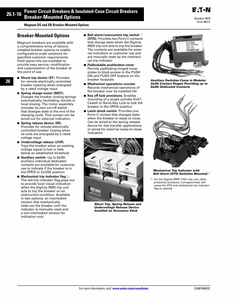
Breaker-Mounted OptionsMagnum breakers are available with a comprehensive array of factory-installed breaker options to enable configured-to-order solutions for specified customer requirements. Field option kits are available to provide easy service, modification and customization of the breaker at the point of use.
■ Shunt trip device (ST). Provides for remote electrically controlled breaker opening when energized by a rated voltage input
■ Spring charge motor (MOT).Charges the breaker closing springs automatically, facilitating remote or local closing. The motor assembly includes its own cut-off switch that changes state at the end of the charging cycle. This contact can be wired out for external indication
■ Spring release device (SR). Provides for remote electrically controlled breaker closing when its coils are energized by a rated voltage input
■ Undervoltage release (UVR). Trips the breaker when an existing voltage signal is lost or falls below an established threshold
■ Auxiliary switch. Up to 6a/6b auxiliary individual dedicated contacts are available for customer use to indicate if the breaker is in the OPEN or CLOSE position
■ Mechanical trip indicator flag 1. The red trip indicator flag pops out to provide local visual indication when the Digitrip RMS trip unit acts to trip the breaker on an overcurrent condition. Available in two options: an interlocked version that mechanically locks out the breaker until the indicator is manually reset and a non-interlocked version for indication only
■ Bell alarm/overcurrent trip switch 1 (OTS). Provides two Form C contacts that change state when the Digitrip RMS trip unit acts to trip the breaker. The contacts are available for exter-nal indication or customer use and are manually reset by the mechani-cal trip indicator
■ Padlockable pushbutton cover. Permits padlocking hinged cover plates to block access to the PUSH ON and PUSH OFF buttons on the breaker faceplate
■ Mechanical operations counter. Records mechanical operations of the breaker over its installed life
■ Key off lock provisions. Enables mounting of a single cylinder Kirk®, Castell or Ronis Key Lock to lock the breaker in the OPEN position
■ Latch check switch. Provides one Form C contact that changes state when the breaker is ready to close. Can be wired to the spring release device for fast transfer applications or wired for external ready-to-close indication
Shunt Trip, Spring Release and Undervoltage Release Device Installed on Accessory Deck
Auxiliary Switches Come in Modular 2a/2b Contact Stages Providing up to 6a/6b Dedicated Contacts
Mechanical Trip Indicator with Bell Alarm (OTS) Switches Mounted 1
1 For the Digitrip RMS 1150+ trip unit, other protective functions, if programmed, will cause the OTS and mechanical trip indicator flag to operate.

26.1-22
For more information, visit: www.eaton.com/consultants CA08104001E
October 2015
Power Circuit Breakers & Insulated-Case Circuit Breakers
Sheet 26
26
Microprocessor Trip UnitsSelection Guide—Magnum DS and SB Digitrip Trip Units
024
Table 26.1-6. Digitrip Trip Units for Magnum DS and SB ANSI/UL Rated Power Circuit Breakers
1 Over and undervoltage alarm or trip, over and underfrequency alarm or trip, voltage unbalance alarm or trip, reverse power trip, and phase rotation alarm are included.
2 1200 A maximum ground fault setting per UL/NEC®.
3 Test set for secondary injection.
Legend: In = Rating Plug and Sensor Rating.Ir = Long Delay Pickup setting.
Trip Unit Type Digitrip 520 Digitrip 520M Digitrip 520MC Digitrip 1150+ 1
Ampere rangeInterrupting rating at 480 V rms sensing
200–6000 A42–200 kA Yes
200–6000 A42–200 kAYes
200–6000 A42–200 kAYes
200–6000 A42–200 kAYes
Protection and CoordinationProtection Ordering options
Fixed rating plug (In)Overtemperature trip
LI, LSI, LSIGYesYes
LSI, LSIG, LSIAYesYes
LSI, LSIG, LSIAYesYes
LSI, LSIG, LSIAYesYes
Long delayprotection (L)
Long delay pickup Long delay time I2t at 6 x Ir Long delay time I4t IEEE curves
0.4–1.0 x (In)2–24 secondsNoNo
0.4–1.0 x (In)2–24 secondsNoNo
0.4–1.0 x (In)2–24 secondsNoNo
0.4–1.0 x (In)2–24 seconds1–5 secondsYes
Long delay thermal memoryHigh load alarm
YesNo
YesNo
YesNo
Yes0.5–1.0 x (Ir)
Short delayprotection (S)
Short delay pickup Short delay time I2t at 8 x Ir Short delay time flatShort delay time ZSI
200–1000% x (Ir) and M1100–500 ms100–500 msYes
200–1000% x (Ir) and M1 100–500 ms100–500 msYes
200–1000% x (Ir) and M1100–500 ms100–500 msYes
200–1000% x (Ir) and M1100–500 ms100–500 msYes
Instanta-neousprotection (I)
Instantaneous pickupMaking current releaseOff position
200–1000% x (In) and M1YesLSI and LSIG
200–1000% x (In) and M1YesYes
200–1000% x (In) and M1YesYes
200–1000% x (In) and M1YesYes
Groundfaultprotection (G) 2
Ground fault alarmGround fault pickupGround fault delay I2t at 0.625 x In
No25–100% x (In)100–500 ms
Yes25–100% x (In) 100–500 ms
Yes25–100% x (In)100–500 ms
Yes24–100% x (In)100–500 ms
Ground fault delay flatGround fault ZSIGround fault thermal memory
100–500 msYesYes
100–500 msYesYes
100–500 msYesYes
100–500 msYesYes
Disable ground fault protection No No No No
Neutral protection (N) Model LSI Model LSI Model LSI Model LSI
System DiagnosticsCause-of-trip LEDsMagnitude of trip information
Yes No
YesYes
Yes Yes
Yes Yes
Remote signal contactsProgrammable contacts
NoNo
Yes No
Yes No
YesYes
System MonitoringDigital displayCurrent (% ) full scale sensor
NoNo
4-character LCDYes ±2%
4-character LCDYes ±2%
24-character LEDYes ±1%
Voltage (%) L to L Power and energy (%) Apparent power kVA and demand
NoNoNo
NoNoNo
NoNoNo
Yes ±1%Yes ± 2%Yes
Reactive power kVARPower factorCrest factor
NoNoNo
NoNoNo
NoNoNo
YesYesYes
Power quality—harmonics% THD, waveform capture
NoNo
NoNo
NoNo
YesYes
System CommunicationsTypePower supply in breaker
NoN/A
NoOptional
INCOMStandard
INCOM/TripLinkStandard
Additional FeaturesTrip log (three events)Electronic operations counter
NoNo
NoNo
NoNo
YesYes
Testing method 3Waveform capture
Test setNo
Test setNo
Test setNo
Integral and test setYes
Arcflash Reduction Maintenance SystemBreaker health monitorProtective relay functions
NoNoNo
NoNoNo
YesNoNo
Yes YesYes 1

CA08104001E For more information, visit: www.eaton.com/consultants
26.1-25October 2015
Power Circuit Breakers & Insulated-Case Circuit Breakers
Sheet 26
26
Magnum DS and SBTechnical Data
027
Table 26.1-7. Magnum DS and SB Breaker Control Device Application Guide—Vdc
Table 26.1-8. Compact Spring Charge Motor
Table 26.1-9. Magnum DS and SB Breaker Control Device Application Guide—Vac
Breaker Control Device
Nominal Voltage
24 Vdc 32 Vdc 48 Vdc 125 Vdc 250 Vdc
Shunt Trip (ST)
Operational voltage range Power consumption (inrush) Opening time
Trip circuit70–110%(required for 35 ms)Seconds
17–26 Vdc250 watts35 ms
—34–53 Vdc250 watts35 ms
77–138 Vdc450 watts35 ms
154–275 Vdc450 watts35 ms
Spring Release (SR)
Operational voltage rangePower consumption (inrush) Closing time
Close circuit70–110%(required for 200 ms)Seconds
17–26 Vdc250 watts35 ms
—34–53 Vdc250 watts35 ms
77–138 Vdc450 watts35 ms
154–275 Vdc450 watts35 ms
Spring Charge Motor (MOT)
Operational voltage rangeAmps (running)Amps (inrush)Power consumptionCharging time
85–110% voltageRunning% of running
Seconds
20–26 Vdc16.0 A200%400 watts2.5 sec
—41–53 Vdc7.5 A600%400 watts2.5 sec
94–138 Vdc3.0 A600%400 watts2.5 sec
187–275 Vdc1.3 A600%350 watts2.5 sec
Undervoltage Release (UVR)
Operational voltage rangeDrop-out voltage rangePower consumption (inrush)Power consumption (continuous)Opening time
85–110% voltage30–60% voltageRequired for 200 msRequired for 400 msSeconds
20–26 Vdc 7–14 Vdc250 watts18 watts70 ms
27–35 Vdc10–19 Vdc275 watts15 watts70 ms
41–53 Vdc14–29 Vdc275 watts18 watts70 ms
94–138 Vdc33–75 Vdc450 watts10 watts70 ms
187–275 Vdc 66–150 Vdc450 watts10 watts70 ms
Auxiliary Switches
Minimum loadContact rating Inductive load 0.5 A
—
0.5 A 0.5 A 0.25 A
Breaker Control Device
Nominal Voltage
24 Vdc 48 Vdc 110–125 Vdc 220–250 Vdc 110–127 Vac 208–240 Vac 208–277 Vac
Spring Charge Motor (MOT)
Operational voltage rangeAmps (running)Amps (inrush)Power consumptionCharging time
85–110% voltageRunning% of runningWatts or VASeconds
20–26 Vac6.0 A600%150 VA5.5 sec
41–53 Vac3.0 A600%150 VA5.5 sec
94–138 Vac1.0 A1200%150 VA5.5 sec
187–275 Vac0.6 A800%150 VA5.5 sec
94–140 Vac1.0 A600%150 VA5.5 sec
177–264 Vac0.75 A667%180 VA5.5 sec
177–305 Vac1.10 A500%300 VA3.5 sec
Breaker Control Device
Nominal Voltage
120 Vac 240 Vac 415 Vac 480 Vac 600 Vac
Shunt Trip (ST) Operational voltage range Power consumption (inrush) Opening time
Trip circuit70–110%(Required for 35 ms)Seconds
77–140 Vac450 VA35 ms
146–264 Vac450 VA35 ms
— — —
Spring Release (SR)
Operational voltage rangePower consumption (inrush) Closing time
Close circuit70–110%(Required for 200 ms)Seconds
77–140 Vac450 VA35 ms
146–264 Vac450 VA35 ms
— — —
Spring Charge Motor (MOT)
Operational voltage rangeAmps (running)Amps (inrush)Power consumptionCharging time
85–110% voltageRunning% of runningWatts or VASeconds
93–140 Vac2.0 A600%250 VA5 sec
177–264 Vac1.0 A600%250 VA5 sec
— — —
Undervoltage Release (UVR)
Operational voltage rangeDrop-out voltage rangePower consumption (inrush)Power consumption (continuous)Opening time
85–110% voltage30–60% voltageRequired for 200 msRequired for 400 msSeconds
94–140 Vac33–76 Vac450 VA10 VA70 ms
177–264 Vac62–144 Vac400 VA10 VA70 ms
323–457 Vac114–249 Vac480 VA10 VA70 ms
408–528 Vac144–288 Vac400 VA10 VA70 ms
510–660 Vac180–360 Vac400 VA10 VA70 ms
Auxiliary Switches
Minimum loadContact rating Inductive load 10 A 10 A
— — —

26.1-26
For more information, visit: www.eaton.com/consultants CA08104001E
October 2015
Power Circuit Breakers & Insulated-Case Circuit Breakers
Sheet 26
26
Magnum DS and SBTechnical Data
028
Figure 26.1-9. Typical Magnum Breaker Control Circuit Diagram
Figure 26.1-10. Typical Magnum Secondary Terminal Block Connection Diagram
ControlPower
Close
B12
Lever in Door Switch(Draw-out Only)
L.S. b.
a.
a.OTS 1*OTS 2*
B15 B26
MDSEOBKR
B10 B24 A7
B13 B14 B27 B11 B25 A8
A1 A2 A3
A4 A5 A6
Open OpenG R
SR
MOT
UVRST
Legend:LS Limit Switch for Closing SpringMOT Motor for Spring ChargingST Shunt Trip 1
SR Spring ReleaseUVR Undervoltage ReleaseOTS Overcurrent Trip Switch
Description of Operation:1 — Motor is energized through
LS contact.2 — Motor runs and charges closing
spring.3 — When closing spring is fully charged,
LS contacts change state.4 — Close contacts energize SR coil.5 — When breaker closes, “b” opens.6 — LS contacts change state and motor
recharges closing springs.
* Contacts shown for breaker open (not fullycharged), not tripped.
Dotted line denotes Magnum Breaker. 1 Continuous Duty Shunt Trip also available
that eliminates the requirement for the “a” contact cutout switch.
1
A1 A2 A3 A4 A5 A6 A7 A8 A9 A10 A11 A12 A13 A14 A15
ONO OC UVRONOONO OC ONO UVR ALL ALC AL ICL
UVR ATROTS OTS ATR
ATR ATR
INCOM CLOSEINPUT
A16 A17 A18 A19 A20 A21 A22 A23 A24 A25 A26 A27 A28 A29 A30
MLS ACN NO NCACP NO NC NO NO NC NC NO NO NC NC
SPRING CHARGESTATUS
ACCESSARYBUSCOMMUN-ICATIONS
BREAKER AUXILIARY CONTACTS(SHOWN WITH BREAKER IN OPEN POSITION)
B16 B17 B18 B19 B20 B21 B22 B23 B24 B25 B26 B27 B28 B29 B30
NO NCNO NO NO NONC NCNC NO NC NC LCO LC LNC
BREAKER AUXILIARY CONTACTS(SHOWN WITH BREAKER IN OPEN POSITION)
LATCHCHECKSWITCH
CELL SWITCH CONTACTS(SHOWN WITH BREAKER IN WITHDRAWN POSITION)
C7 C8 C9 C10 C11 C12
CNC CC CNO CNC CC CNO
CELL SWITCH CONTACTS(SHOWN WITH BREAKER IN WITHDRAWN POSITION)
CNC CC CNO CNC CC CNO
C1 C2 C3 C4 C5 C6
INCOM NEGPOWERINPUT
NEUTRALSENSORINPUT
SOURCEGROUNDINPUT
ZONEINTER-LOCKING
SHUNTTRIP
SPRINGRELEASE
MOTOR
COM IN OUT
B1 B2 B3 B4 B5 B6 B7 B8 B9 B10 B11 B12 B13 B14 B15
IP IN NPW N2 N1 SGF ZC ZI ZO ST ST SR SR M M

CA08104001E For more information, visit: www.eaton.com/consultants
26.1-31October 2015
Power Circuit Breakers & Insulated-Case Circuit Breakers
Sheet 26
26
Magnum DS and SBAccessories and Peripheral Devices
033
Accessories and Peripheral Devices
Levering Tool
Levering Tool
Magnum drawout breakers are designed for closed door manual levering by use of a standard 3/8-inch (10 mm) drive set, which is a commonly available tool. This eliminates the need for a unique levering device, which tends to get lost if not properly stored.
Magnum Remote Racking Device
Magnum Breaker Remote Racking Device
Eaton’s MRR1000 remote racking device provides a means of remotely inserting or removing any drawout circuit breaker in the Magnum DS and SB family of air circuit breakers (ACBs), to help mitigate arc flash exposure. The MRR1000 permits the operator to remotely open and close a breaker from up to 25 feet away during the rack-in or rack-out process, a distance well beyond the arc flash boundary for traditional LV switchgear.
■ 120 Vac power supply (with plug) ■ Works with all breakers in the
Magnum family (MDS, MDN, SBS, SBN and CM52 network protectors)
■ Locking fixture mounts directly to Magnum breaker escutcheon
■ 25-foot umbilical cord between the operator and the device
■ Hand-held pendant with OPEN/CLOSE and IN/OUT pushbuttons, with ENABLE button
■ Ready lights indicating power to the unit and pendant
■ Safety interlock prevents operation of unit until it is safely locked in place
■ Complete racking in 25 seconds or less
■ Handles for ease of installation■ Works on new and existing
Magnum breakers without the need for any modifications to doors, breakers or structures
MRR1000 Connected to Magnum Breaker
Universal Remote Power Racking System (Type RPR-2)
Remote Power Racking System
For maximum safety during drawout breaker levering operations, the universal remote power racking system (RPR-2) can be employed on Magnum, as well as other drawout low and medium voltage power circuit breakers that use rotation of a shaft for insertion or removal. Remote control is accom-plished by an operator pendant with an INSERT and REMOVE pushbutton station and a 25-foot connecting cable. The RPR-2 requires 120 Vac, 15 A power from a common plug receptacle. Status indication and selectable torque limitation matched to the breaker racking mechanism are also provided.
Lifting Yoke and Floor Lifting DeviceMagnum breakers include lifting ears on each side to accept a lifting yoke (or suitable sling) to facilitate lifting using a skyhook from a top of gear lifter, floor lifter or crane. Various lifting yoke style numbers are available for all Magnum frame types in both three-pole and four-pole configurations.
A roll-on-the-floor lifting device style number 6727D63H20 is equipped with a skyhook for use in conjunction with a breaker lifting yoke or suitable sling to lift the breaker from above. Shelf-type roll-on-the-floor lifters can also be used to lift the breaker from underneath without a lifting yoke.
Floor Lifting Device
26.1-32
For more information, visit: www.eaton.com/consultants CA08104001E
October 2015
Power Circuit Breakers & Insulated-Case Circuit Breakers
Sheet 26
26
Magnum DS and SBAccessories and Peripheral Devices
034
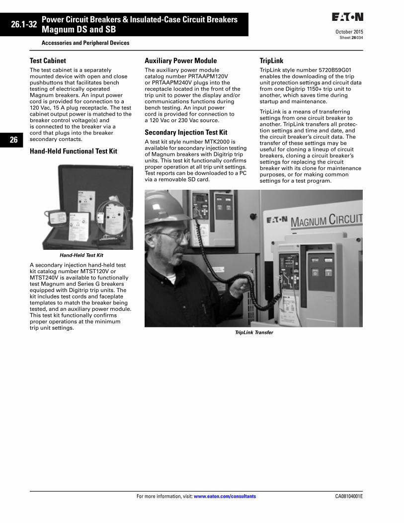
Test CabinetThe test cabinet is a separately mounted device with open and close pushbuttons that facilitates bench testing of electrically operated Magnum breakers. An input power cord is provided for connection to a 120 Vac, 15 A plug receptacle. The test cabinet output power is matched to the breaker control voltage(s) and is connected to the breaker via a cord that plugs into the breaker secondary contacts.
Hand-Held Functional Test Kit
Hand-Held Test Kit
A secondary injection hand-held test kit catalog number MTST120V or MTST240V is available to functionally test Magnum and Series G breakers equipped with Digitrip trip units. The kit includes test cords and faceplate templates to match the breaker being tested, and an auxiliary power module. This test kit functionally confirms proper operations at the minimum trip unit settings.
Auxiliary Power ModuleThe auxiliary power module catalog number PRTAAPM120V or PRTAAPM240V plugs into the receptacle located in the front of the trip unit to power the display and/or communications functions during bench testing. An input power cord is provided for connection to a 120 Vac or 230 Vac source.
Secondary Injection Test KitA test kit style number MTK2000 is available for secondary injection testing of Magnum breakers with Digitrip trip units. This test kit functionally confirms proper operation at all trip unit settings. Test reports can be downloaded to a PC via a removable SD card.
TripLinkTripLink style number 5720B59G01 enables the downloading of the trip unit protection settings and circuit data from one Digitrip 1150+ trip unit to another, which saves time during startup and maintenance.
TripLink is a means of transferring settings from one circuit breaker to another. TripLink transfers all protec-tion settings and time and date, and the circuit breaker’s circuit data. The transfer of these settings may be useful for cloning a lineup of circuit breakers, cloning a circuit breaker’s settings for replacing the circuit breaker with its clone for maintenance purposes, or for making common settings for a test program.
TripLink Transfer
27.4-26
For more information, visit: www.eaton.com/consultants CA08104001E
April 2016
Molded-Case Circuit Breakers & Enclosures
Sheet 27
27
Circuit Breaker Selection DataSeries C Selection Data—F-Frame
102
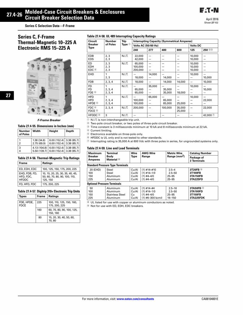
Series C, F-FrameThermal-Magnetic 10–225 AElectronic RMS 15–225 A
F-Frame Breaker
Table 27.4-55. Dimensions in Inches (mm)
Table 27.4-56. Thermal-Magnetic Trip Ratings
Table 27.4-57. Digitrip 310+ Electronic Trip Units
Number
of Poles
Width Height Depth
12
1.38 (34.8)2.75 (69.9)
6.00 (152.4)6.00 (152.4)
3.38 (85.7)3.38 (85.7)
34
4.13 (104.8)5.50 (139.7)
6.00 (152.4)6.00 (152.4)
3.38 (85.7)3.38 (85.7)
Frame Ratings
ED, EDH, EDC 100, 125, 150, 175, 200, 225
EHD, FDB, FD,HFD, FDC, HFDDC
10, 15, 20, 25, 30, 35, 40, 45,50, 60, 70, 80, 90, 100, 110,125, 150
FD, HFD, FDC 175, 200, 225
Types Frame Ratings
FDE, HFDE,FDCE
225 100, 110, 125, 150, 160,175, 200, 225
160 60, 70, 80, 90, 100, 125, 150, 160
80 15, 20, 30, 40, 50, 60, 70, 80
Table 27.4-58. UL 489 Interrupting Capacity Ratings
1 N.I.T. is non-interchangeable trip unit.2 Two-pole circuit breaker, or two poles of three-pole circuit breaker.3 Time constant is 3 milliseconds minimum at 10 kA and 8 milliseconds minimum at 22 kA.4 Current limiting.5 Electronics available on three-pole only.6 HFDDC is UL only and is not tested to other standards.7 Interrupting rating is 35,000 A at 600 Vdc with three poles in series, for ungrounded systems only.
Table 27.4-59. Line and Load Terminals
8 UL listed for use with copper or aluminum conductors as noted.9 Not for use with ED, EDH, EDC breakers.
Circuit
Breaker
Type
Number
of Poles
Trip
Type 1Interrupting Capacity (Symmetrical Amperes)
Volts AC (50/60 Hz) Volts DC
240 277 480 600 125 250 23
EDBEDS
2, 32, 3
N.I.T. 22,00042,000
——
——
——
10,00010,000
——
EDEDHEDC 4
2, 32, 32, 3
N.I.T. 65,000100,000200,000
———
———
———
10,00010,00010,000
———
EHD 12, 3
N.I.T. —18,000
14,000—
—14,000
——
10,000—
—10,000
FDB 2, 3, 4 N.I.T. 18,000 — 14,000 14,000 — 10,000
FDFDFDE 5
12, 3, 42, 3, 4
N.I.T. —65,00065,000
35,000——
—35,00035,000
——18,000
10,000——
—10,000—
HFDHFDHFDE 5
12, 3, 42, 3, 4
N.I.T. —100,000100,000
65,000——
—65,00065,000
——25,000
10,000——
—22,000—
FDC 4FDCE 5
2, 3, 4 N.I.T. 200,000 — 100,000 35,00025,000
— 22,000
HFDDC 6 3 N.I.T. — — — — — 42,000 7
Maximum
Breaker
Amperes
Terminal
Body
Material 8
Wire
Type
AWG Wire
Range
Metric Wire
Range (mm2)
Catalog Number
Package of
3 Terminals
Standard Pressure Type Terminals20 (EHD)
100150225
SteelSteelAluminumAluminum
Cu/AlCu/AlCu/AlCu/Al
(1) #14–#10(1) #14–1/0(1) #4–4/0(1) #4–4/0
2.5–42.5–50
25–9525–95
3T20FB 9
3T100FB
3TA150FB
3TA225FD
Optional Pressure Terminals50
100150225
AluminumAluminumStainless SteelAluminum
Cu/AlCu/AlCuCu/Al
(1) #14–#4(1) #14–1/0(1) #4–4/0(1) #6–300 kcmil
2.5–162.5–50
25–9516–150
3TA50FB 9
3TA100FD
3T150FB
3TA225FDK

CA08104001E For more information, visit: www.eaton.com/consultants
27.1-7April 2016
Molded-Case Circuit Breakers & Enclosures
Sheet 27
22
23
24
25
26
27
28
29
30
31
32
33
34
35
36
37
38
39
40
41
42
43
Molded-Case Circuit BreakersAccessories and Modifications
011
Internal AccessoriesNote: For a complete listing of available external accessories, see Volume 4—Circuit Protection Catalog, CA08100005E, Section 25.
All internal accessories are of the plug-in type and are listed for field installation under UL File E64983. Internal accessories for sealed circuit breakers are listed under UL File E7819 for factory installation only. The available plug-in accessories include the following:
■ Alarm (signal)/lockout switch■ Auxiliary switch■ Shunt trip■ Low energy shunt trip■ Undervoltage release mechanism
Typical Internal Plug-in Accessory Installed in K-Frame Circuit Breaker
Different accessory wiring options are available to satisfy most circuit breaker mounting applications. The standard wiring configuration is pigtail leads exiting the rear of the base directly behind the accessory. Optional configurations include a terminal block mounted on the same side of the base as the accessory, leads exiting the side of the base where the accessory is mounted, and leads exiting the rear of the base on the side opposite the accessory. If accessory leads longer than 18.00 inches (457.2 mm) are required, side-mounted terminal blocks should be used.
Alarm (Signal)/Lockout SwitchThe alarm (signal)/lockout switch monitors circuit breaker trip status and provides remote signaling and inter-locking capabilities when the circuit breaker trips. For two-, three- and four-pole circuit breakers, the alarm (signal)/lockout switch consists of one or two SPDT switches assembled to a plug-in module mounted in retaining slots in the top of the trip unit. The SPDT switch contacts are identified as make and break contacts. When the circuit breaker trips, the make contact closes and the break contact opens.
Alarm (Signal)/Lockout Switch
Auxiliary SwitchThe auxiliary switch provides circuit breaker contact status information by monitoring the position of the molded crossbar containing the moving contact arms. The auxiliary switch is used for remote signaling and interlocking purposes, and consists of one or two SPDT switches assembled to a plug-in module mounted in retaining slots in the top of the trip unit. Each SPDT switch has one “a” and one “b” contact. When the circuit breaker contacts are open, the ”a“ contact is open and the “b” contact is closed.
Auxiliary Switch
Shunt TripThe shunt trip provides remote controlled tripping of the circuit breaker. The shunt trip consists of an intermittent rated solenoid with a tripping plunger and a cutoff switch assembled to a plug-in module. When required for ground fault protection applications, certain AC rated shunt trips are suitable for operation at 55% of rated voltage.
Available in most AC and DC voltages.
Note: Approximate unlatching time—6 milliseconds. Approximate total circuit breaker contact opening time—18 milliseconds. Endurance—4000 electrical operations plus 1000 mechanical operations. Supply voltages suitable for use with Class 1 GFP devices. Marking label included with accessory kits.
Shunt Trip
OPTIM Communications KitEaton’s OPTIM Communications Kit provides the option to field install PowerNet communications into a K-, L- or N-Frame OPTIM 550 breaker. OPTIM 1050 trip units come equipped with communications as standard.
OPTIM Communications Kit
Make
Break
a
b
ST
a

27.1-8
For more information, visit: www.eaton.com/consultants CA08104001E
April 2016
Molded-Case Circuit Breakers & Enclosures
Sheet 27
22
23
24
25
26
27
28
29
30
31
32
33
34
35
36
37
38
39
40
41
42
43
Molded-Case Circuit BreakersAccessories and Modifications
012
Low Energy Shunt TripLow energy shunt trip devices are designed to operate from low energy output signals from dedicated current sensors typically applied in ground fault protection schemes. However, with a proper control voltage source, they may be applied in place of conventional trip devices for special applications. Flux paths surrounding permanent magnets used in the shunt trip assembly hold a charged spring poised in readiness to operate the circuit breaker trip mechanism. When a 100 microfarad capacitor charged to 28 Vdc is discharged through the shunt trip coil, the resultant flux opposes the permanent magnet flux field, which releases the stored energy in the spring to trip the circuit breaker. As the circuit breaker resets, the reset arm is actuated by the circuit breaker handle, resetting the shunt trip. The plug-in module is mounted in retaining slots in the top of the trip unit. Coil is intermittent-rated only. Cutoff provisions required in control circuit.
Low Energy Shunt Trip
Undervoltage Release Mechanism The undervoltage release mechanism monitors a voltage (typically a line voltage) and trips the circuit breaker when the voltage falls to between 70 and 35% of the solenoid coil rating.
Note: Undervoltage release mechanism accessories are not designed for, and should not be used as, circuit interlocks.
The undervoltage release mechanism consists of a continuous rated solenoid with a plunger and tripping lever assembled to a plug-in module.
The tab on the tripping lever resets the undervoltage release mechanism when normal voltage has been restored and the circuit breaker handle is moved to the reset (OFF) position.
With no voltage applied to the under-voltage release mechanism, the circuit breaker contacts will not touch when a closing operation is attempted.
Undervoltage Release Mechanism
External AccessoriesNote: For a complete listing of available external accessories, see Volume 4—Circuit Protection Catalog, CA08100005E, Section 25.
Non-Padlockable Handle BlockThe nonlockable handle block secures the circuit breaker handle in either the ON or OFF position. (Trip-free operation allows the circuit breaker to trip when the handle block holds the circuit breaker handle in the ON position.) The device is positioned over the circuit breaker handle and secured by a set-screw to deter accidental operation of the circuit breaker handle. (Field installation only.)
Non-Padlockable Handle Block
Padlockable Handle Lock HaspThe padlockable handle lock hasp allows the handle to be locked in the ON or OFF position. (Trip-free operation allows the circuit breaker to trip when the handle lock holds the circuit breaker handle in the ON position.) The hasp mounts on the circuit breaker cover within the trimline. The cover is predrilled on both sides of the operating handle so that the hasp can be mounted on either side of the handle. The hasp will accommodate up to three padlocks with 1/4-inch(6.4 mm) shackles. One per circuit breaker. (Field installation only.)
Padlockable Handle Lock Hasp
Key Interlock Kit (Lock Not Included)The key interlock is used to externally lock the circuit breaker handle in the OFF position. When the key interlock is locked, an extended deadbolt blocks movement of the circuit breaker handle. Uniquely coded keys are removable only with the deadbolt extended. Each coded key controls a group of circuit breakers for a given specific customer installation.
The key interlock assembly consists of a mounting kit and a purchaser supplied deadbolt lock. The mounting kit comprises a mounting plate, which is secured to the circuit breaker cover in either the left- or right-pole position; key interlock mounting hardware; and a wire seal. Specific mounting kits are required for individual key interlock types. (Field installation only.)
Key Interlock Kit
Padlockable Handle BlockThe device is positioned in the cover opening to prevent handle movement. Will accommodate one 5/16-inch (8.0 mm) padlock.
Padlockable Handle Block
STLE
UV

27.4-28
For more information, visit: www.eaton.com/consultants CA08104001E
April 2016
Molded-Case Circuit Breakers & Enclosures
Sheet 27
27
Circuit Breaker Selection DataSeries C Selection Data—K-Frame
104
Series C, K-FrameElectronic RMS, 70–400 AThermal-Magnetic, 100–400 A
K-Frame Breaker
Table 27.4-64. Dimensions in Inches (mm)
Table 27.4-65. Thermal-Magnetic Trip Ratings
Table 27.4-66. Digitrip 310+ Electronic Trip Units
Table 27.4-67. Digitrip OPTIM Electronic Trip Unit Rating Plugs
Number
of Poles
Width Height Depth
2, 3 5.50 (139.7)
10.13 (257.2)
4.06 (103.2)
4 7.22 (183.4)
10.13 (257.2)
4.06 (103.2)
Frame Ratings
DK, KDB, KD, HKD, KDC, HKDDC,
100, 125, 150, 175, 200,225, 250, 300, 350, 400
Frame Ratings
KD, CKD, HKD,CHKD, KDC
55, 60, 70, 90, 100, 110, 125, 150, 160, 175, 200, 225, 250, 300, 315, 350, 400
Frame Rating Plugs
KD, CKD, HKD,CHKD, KDC
70, 90, 100, 110, 125, 150, 175, 200, 225, 250, 300, 350, 400
Table 27.4-68. NEMA/UL 489/CSA Interrupting Capacity Ratings
1 N.I.T. is non-interchangeable trip; I.T. is interchangeable trip.2 Two-pole circuit breaker or two outside poles of three-pole circuit breaker.3 Time constant is 3 milliseconds minimum at 10 kA and 8 milliseconds minimum at 22 kA.4 8 milliseconds time constant.5 Current limiting.6 100% rated.7 Two poles in series.h Three poles in series.
Table 27.4-69. Line and Load Terminals
i Individually packed.j Terminal kits contain one terminal for each pole and one terminal cover.k Two-pole kit.l Three-pole kit.m Four-pole kit.n Terminal kits contain one terminal for each pole and three interphase barriers.
Circuit
Breaker
Type
Number
of Poles
Trip
Type 1Interrupting Capacity (Symmetrical Amperes)
Volts AC (50/60 Hz) Volts DC
240 480 600 250 23 600 4
DKKDBKD
2, 32, 3, 42, 3, 4
N.I.T.N.I.T.I.T.
65,00065,00065,000
—35,00035,000
—25,00025,000
10,00010,00010,000
———
HKDKDC 5HKDDC
2, 3, 42, 3, 43
I.T.I.T.I.T.
100,000200,000—
65,000100,000—
35,00065,000—
22,00022,00042,000 7
——35,000 h
CKD 6CHKD 6
33
I.T.I.T.
65,000100,000
35,00065,000
25,00035,000
——
——
Maximum
Breaker
Amperes
Terminal
Body
Material
Wire
Type
AWG/Wire
Range/Number
Conductors
Metric
Wire
Range (mm2)
Catalog
Number
Standard Cu/Al Pressure Terminals225350
AluminumAluminum
Cu/AlCu/Al
3–350 (1)250–500 (1)
35–185120–240
TA300K i
TA350K i
400 Aluminum Cu/Al 3/0–250 (2) 95–120 2TA400K jk
3TA400K jl
4TA400K mn
Optional Copper and Cu/Al Pressure Type Terminals225350
CopperCopper
CuCu
3–350 (1)50–500 (1)
35–185120–240
T300K i
T350K i
400 Copper Cu 3/0–250 (2) 95–120 2T400K k
3T400K l
4T400K m
400 Aluminum Cu/Al 2/0–250 (2)or2/0–500 (1)
70–12070–24070–240
2TA401K jk
3TA401K jl
4TA401K mn
400 Aluminum Cu/Al 500–750 (1) 300–400 2TA402K jk
3TA402K jl
4TA402K mn
400 Copper Cu/Al 500–750 (1) — 2T402K jk
3T402K jl
4T402K mn


Detail Bill of Material Page 1 of 5
Project Name: Home 2 Flowood Negotiation No: MH880916X6K3 General Order No:
Alternate No: 0002
Item No. Qty Product Description 1 Panelboards 42 Circuits, 225A, Fully Rated, 208Y/120V 3Ph 4W, Aluminum
Bus, 10k AIC, 225A, Main Lugs Only[Bottom Fed], Surface Mounted
Catalog No P1A225LB42AH01 Designation CA
Qty List of Materials 1 225A, Main Lugs Only 34 20A, 1P BAB Branch Breaker 2 20A, 2P BAB Branch Breaker 2 30A, 2P BAB Branch Breaker 1 Std. Bolted Al Ground Bar (Al/Cu Cable) 1 Panel Nameplate - White with Black Letters 1 Type 1 Enclosure: EZB2042R 1 EZ Trim, Door in Door, Concealed Hardware: EZT2042S
Item No. Qty Product Description 2 Panelboards 42 Circuits, 225A, Fully Rated, 208Y/120V 3Ph 4W, Aluminum
Bus, 10k AIC, 225A, Main Lugs Only[Bottom Fed], Surface Mounted
Catalog No P1A225LB42AH01 Designation CB
Qty List of Materials 1 225A, Main Lugs Only 40 20A, 1P BAB Branch Breaker 2 20A, 1P QBGFT Branch Breaker, GFCI - 5mA 1 Std. Bolted Al Ground Bar (Al/Cu Cable) 1 Panel Nameplate - White with Black Letters 1 Type 1 Enclosure: EZB2042R 1 EZ Trim, Door in Door, Concealed Hardware: EZT2042S
Item No. Qty Product Description 1 Panelboards 42 Circuits, 225A, Fully Rated, 208Y/120V 3Ph 4W, Aluminum
Bus, 10k AIC, 225A, Main Lugs Only[Bottom Fed], Surface Mounted
Catalog No P1A225LB42AH01 Designation OL
Qty List of Materials 1 225A, Main Lugs Only 21 20A, 1P QBGFT Branch Breaker, GFCI - 5mA 19 20A, 1P BAB Branch Breaker 1 20A, 2P QBGFT Branch Breaker, GFCI - 5mA 1 Std. Bolted Al Ground Bar (Al/Cu Cable) 1 Panel Nameplate - White with Black Letters 1 Type 1 Enclosure: EZB2042R 1 EZ Trim, Door in Door, Concealed Hardware: EZT2042S

Detail Bill of Material Page 2 of 5
Project Name: Home 2 Flowood Negotiation No: MH880916X6K3 General Order No:
Alternate No: 0002
Item No. Qty Product Description 1 Panelboards 18 Circuits, 100A, Fully Rated, 208Y/120V 3Ph 4W, Aluminum
Bus, 10k AIC, 100A, Main Lugs Only[Top Fed], Flush Mounted
Catalog No P1A100LT18AH01 Designation PBX
Qty List of Materials 1 100A, Main Lugs Only 12 20A, 1P BAB Branch Breaker 6 1P BAB Branch Provision Only 1 Insulated / Isolated and Std Al Ground Bar (Al/Cu Cable) 1 Panel Nameplate - White with Black Letters 1 Type 1 Enclosure: EZB2036R 1 EZ Trim, Door in Door, Concealed Hardware: EZT2036F
Item No. Qty Product Description 1 Panelboards 30 Circuits, 225A, Fully Rated, 208Y/120V 3Ph 4W, Aluminum
Bus, 10k AIC, 225A, Main Lugs Only[Bottom Fed], Surface Mounted
Catalog No P1A225LB30AH01 Designation K
Qty List of Materials 1 225A, Main Lugs Only 3 30A, 1P BAB Branch Breaker 1 50A, 3P BAB-H Branch Breaker 24 20A, 1P BAB Branch Breaker 1 Std. Bolted Al Ground Bar (Al/Cu Cable) 1 Panel Nameplate - White with Black Letters 1 Type 1 Enclosure: EZB2036R 1 EZ Trim, Door in Door, Concealed Hardware: EZT2036S
Item No. Qty Product Description 1 Panelboards 42 Circuits, 225A, Fully Rated, 208Y/120V 3Ph 4W, Aluminum
Bus, 10k AIC, 225A, Main Lugs Only[Bottom Fed], Surface Mounted
Catalog No P1A225LB42AH01 Designation LDY
Qty List of Materials 1 225A, Main Lugs Only 7 30A, 3P BAB-H Branch Breaker 1 40A, 3P BAB-H Branch Breaker 1 20A, 2P BAB Branch Breaker 2 20A, 1P QBGFT Branch Breaker, GFCI - 5mA 14 20A, 1P BAB Branch Breaker 1 Std. Bolted Al Ground Bar (Al/Cu Cable) 1 Panel Nameplate - White with Black Letters 1 Type 1 Enclosure: EZB2042R 1 EZ Trim, Door in Door, Concealed Hardware: EZT2042S

Detail Bill of Material Page 3 of 5
Project Name: Home 2 Flowood Negotiation No: MH880916X6K3 General Order No:
Alternate No: 0002
Item No. Qty Product Description 1 Panelboards 42 Circuits, 225A, Fully Rated, 208Y/120V 3Ph 4W, Aluminum
Bus, 10k AIC, 225A, Main Lugs Only[Bottom Fed], Surface Mounted
Catalog No P1A225LB42AH01 Designation HAC
Qty List of Materials 1 225A, Main Lugs Only 1 30A, 2P BAB Branch Breaker 1 30A, 3P BAB-H Branch Breaker 5 20A, 2P BAB Branch Breaker 1 15A, 3P BAB-H Branch Breaker 1 50A, 2P BAB Branch Breaker 11 20A, 1P BAB Branch Breaker 3 40A, 3P BAB-H Branch Breaker 1 40A, 2P BAB Branch Breaker 1 Std. Bolted Al Ground Bar (Al/Cu Cable) 1 Panel Nameplate - White with Black Letters 1 Type 1 Enclosure: EZB2048R 1 EZ Trim, Door in Door, Concealed Hardware: EZT2048S
Item No. Qty Product Description 1 Panelboards 18 Circuits, 100A, Fully Rated, 208Y/120V 3Ph 4W, Aluminum
Bus, 10k AIC, 100A, Main Lugs Only[Top Fed], Flush Mounted
Catalog No P1A100LT18AH01 Designation FD
Qty List of Materials 1 100A, Main Lugs Only 18 20A, 1P BAB Branch Breaker 1 Std. Bolted Al Ground Bar (Al/Cu Cable) 1 Panel Nameplate - White with Black Letters 1 Type 1 Enclosure: EZB2036R 1 EZ Trim, Door in Door, Concealed Hardware: EZT2036F
Item No. Qty Product Description 1 Panelboards 18 Circuits, 100A, Fully Rated, 208Y/120V 3Ph 4W, Aluminum
Bus, 10k AIC, 100A, Main Lugs Only[Bottom Fed], Surface Mounted
Catalog No P1A100LB18AH01 Designation PL
Qty List of Materials 1 100A, Main Lugs Only 9 20A, 1P BAB Branch Breaker 5 20A, 1P QBGFT Branch Breaker, GFCI - 5mA 1 60A, 2P BAB Branch Breaker 1 20A, 2P QBGFT Branch Breaker, GFCI - 5mA 1 Std. Bolted Al Ground Bar (Al/Cu Cable) 1 Panel Nameplate - White with Black Letters 1 Type 1 Enclosure: EZB2036R 1 EZ Trim, Door in Door, Concealed Hardware: EZT2036S

Detail Bill of Material Page 4 of 5
Project Name: Home 2 Flowood Negotiation No: MH880916X6K3 General Order No:
Alternate No: 0002
Item No. Qty Product Description 1 Panelboards 30 Circuits, 400A, Fully Rated, 208Y/120V 3Ph 4W, Aluminum
Bus, 10k AIC, 400A, Main Lugs Only[Bottom Fed], Surface Mounted
Catalog No P3A400LB36AH3R Designation RF
Qty List of Materials 1 400A, Main Lugs Only 2 15A, 1P BAB Branch Breaker 8 20A, 1P BAB Branch Breaker 2 30A, 3P BAB-H Branch Breaker 1 20A, 3P BAB-H Branch Breaker 1 25A, 3P BAB-H Branch Breaker 1 20A, 2P BAB Branch Breaker 2 110A, 3P FDB Branch Breaker 1 Std. Bolted Al Ground Bar (Al/Cu Cable) 1 Panel Nameplate - White with Black Letters 1 Type 3R Enclosure: LWPQ2072
Item No. Qty Product Description 4 Panelboards 30 Circuits, 225A, Fully Rated, 208Y/120V 3Ph 4W, Aluminum
Bus, 10k AIC, 225A, Main Lugs Only[Bottom Fed], Surface Mounted
Catalog No P1A225LB30AH3R Designation 2D,3D,4D,5D
Qty List of Materials 1 225A, Main Lugs Only 5 100A, 2P BAB Branch Breaker 20 20A, 1P BAB Branch Breaker 1 Std. Bolted Al Ground Bar (Al/Cu Cable) 1 Panel Nameplate - White with Black Letters 1 Type 3R Enclosure: LWPQ2036
Item No. Qty Product Description 14 Panelboards 42 Circuits, 225A, Fully Rated, 208Y/120V 3Ph 4W, Aluminum
Bus, 10k AIC, 225A, Main Lugs Only[Bottom Fed], Surface Mounted
Catalog No P1A225LB42AH3R Designation 2A,2B,2C,3A,3B,3C,4A,4B,4C,5A,5B,5C,1A,1B
Qty List of Materials 1 225A, Main Lugs Only 8 100A, 2P BAB Branch Breaker 8 20A, 1P BAB Branch Breaker 18 1P BAB Branch Provision Only 1 Std. Bolted Al Ground Bar (Al/Cu Cable) 1 Panel Nameplate - White with Black Letters 1 Type 3R Enclosure: LWPQ2042

Detail Bill of Material Page 5 of 5
Project Name: Home 2 Flowood Negotiation No: MH880916X6K3 General Order No:
Alternate No: 0002
Item No. Qty Product Description 1 Panelboards 30 Circuits, 100A, Fully Rated, 208Y/120V 3Ph 4W, Aluminum
Bus, 10k AIC, 100A, Main Lugs Only[Bottom Fed], Surface Mounted
Catalog No P1A100LB30AH01 Designation PH
Qty List of Materials 1 100A, Main Lugs Only 30 20A, 1P BAB Branch Breaker 1 Std. Bolted Al Ground Bar (Al/Cu Cable) 1 Panel Nameplate - White with Black Letters 1 Type 1 Enclosure: EZB2036R 1 EZ Trim, Door in Door, Concealed Hardware: EZT2036S
Eaton Selling Policy None applies.
All orders must be released for manufacture within 90 days of date of order entry. If approval drawings are required, drawings must be returned
approved for release within 60 days of mailing. If drawings are not returned accordingly, and/or if shipment is delayed for any reason, the price of the
order will increase by 1.0% per month or fraction there of for the time the shipment is delayed.

1 2
3 4
5 6
7 8
9 10
11 12
13 14
15 16
17 18
19 20
21 22
23 24
25 26
27 28
29 30
31 32
33 34
35 36
37 38
39 40
41 42
Blank Cover2 inches
BAB1020BAB1020BAB1020
BAB1020 BAB1020BAB1020 BAB1020BAB1020 BAB1020BAB1020 BAB1020BAB1020 BAB1020BAB1020 BAB1020BAB1020 BAB1020BAB1020 BAB1020BAB1020 BAB1020BAB1020 BAB1020BAB1020 BAB1020BAB1020 BAB1020BAB1020 BAB1020
BAB1020BAB1020BAB1020
BAB2020
BAB2020BAB2030BAB1020BAB1020
BAB2030
Main Lugs Only225A
General Information (Section 1 of 1)
Service Voltage: 208Y/120V 3Ph 4W Enclosure: Type 1Bus Rating & Type: 225A Aluminum Neutral Rating: 225AGround Bar: Std. Bolted Aluminum, Al or Cu cableS.C. Rating: 10k A.I.C. Fully Rated
Main Device Type: Main Lugs Only - Bottom Cable EntryMain Terminals: Mechanical - (1) #6-300 kcmil (Cu/Al)Neutral Terminals: Mechanical - (1) #6-300 kcmil (Cu/Al)Box Catalog No.: EZB2042RTrim: EZ Trim, Door in Door, Concealed Hardware (EZT2042S)
Surface Mounted
Box Dimensions: 42.00" [1066.8mm]H x 20.00" [508.0mm]W x 5.75" [146.1mm]DMin. Gutter Size: Top = 5.5" [139.7mm] Bottom = 5.5" [139.7mm]
Left = 6.0" [152.4mm] Right = 6.0" [152.4mm]
Panel ID Nameplate: (1) CAType: Plastic, adhesive-backed (2) 208Y/120V 3Ph 4WColor: White with Black Letters (3)
UL
Trim Lock: Standard Lock & Key (Keyed WEM2)Circuit Directory: Plastic Sleeve with Card
Branch DevicesQty Poles Trip Frame Amps kAIC34 1 20 BAB 100 102 2 20 BAB 100 102 2 30 BAB 100 10
Device Modifications:Ref # Description
Notes:
NEG-ALT Number
PREPARED BY DATE
APPROVED BY DATE
VERSION
REVISION DWG SIZE
JOB NAME
DESIGNATION
TYPE
G.O.
DRAWING TYPE
ITEM SHEET
The information on this document is created by Eaton Corporation. It is disclosed in confidence and it is only to be used for the purpose in which it is supplied.
MH880916X6K3-0002
TROY VANHOESEN 1/18/2017
1.0.0.12
0 A
EatonHome 2 FlowoodCA
PRL1a Customer Approval
1 of 1

1 2
3 4
5 6
7 8
9 10
11 12
13 14
15 16
17 18
19 20
21 22
23 24
25 26
27 28
29 30
31 32
33 34
35 36
37 38
39 40
41 42
Blank Cover2 inches
BAB1020 BAB1020BAB1020 BAB1020BAB1020 BAB1020BAB1020 BAB1020BAB1020 BAB1020BAB1020 BAB1020BAB1020 BAB1020
BAB1020BAB1020
BAB1020 BAB1020BAB1020 BAB1020BAB1020 BAB1020BAB1020 BAB1020BAB1020 BAB1020BAB1020 BAB1020BAB1020 BAB1020BAB1020 BAB1020BAB1020 BAB1020BAB1020 BAB1020BAB1020 BAB1020
QBGFT1020BAB1020
QBGFT1020
BAB1020
Main Lugs Only225A
General Information (Section 1 of 1)
Service Voltage: 208Y/120V 3Ph 4W Enclosure: Type 1Bus Rating & Type: 225A Aluminum Neutral Rating: 225AGround Bar: Std. Bolted Aluminum, Al or Cu cableS.C. Rating: 10k A.I.C. Fully Rated
Main Device Type: Main Lugs Only - Bottom Cable EntryMain Terminals: Mechanical - (1) #6-300 kcmil (Cu/Al)Neutral Terminals: Mechanical - (1) #6-300 kcmil (Cu/Al)Box Catalog No.: EZB2042RTrim: EZ Trim, Door in Door, Concealed Hardware (EZT2042S)
Surface Mounted
Box Dimensions: 42.00" [1066.8mm]H x 20.00" [508.0mm]W x 5.75" [146.1mm]DMin. Gutter Size: Top = 5.5" [139.7mm] Bottom = 5.5" [139.7mm]
Left = 6.0" [152.4mm] Right = 6.0" [152.4mm]
Panel ID Nameplate: (1) CBType: Plastic, adhesive-backed (2) 208Y/120V 3Ph 4WColor: White with Black Letters (3)
UL
Trim Lock: Standard Lock & Key (Keyed WEM2)Circuit Directory: Plastic Sleeve with Card
Branch DevicesQty Poles Trip Frame Amps kAIC40 1 20 BAB 100 102 1 20 QBGFT 100 10
Device Modifications:Ref # Description
Notes:
NEG-ALT Number
PREPARED BY DATE
APPROVED BY DATE
VERSION
REVISION DWG SIZE
JOB NAME
DESIGNATION
TYPE
G.O.
DRAWING TYPE
ITEM SHEET
The information on this document is created by Eaton Corporation. It is disclosed in confidence and it is only to be used for the purpose in which it is supplied.
MH880916X6K3-0002
TROY VANHOESEN 1/18/2017
1.0.0.12
0 A
EatonHome 2 FlowoodCB
PRL1a Customer Approval
1 of 1

1 2
3 4
5 6
7 8
9 10
11 12
13 14
15 16
17 18
19 20
21 22
23 24
25 26
27 28
29 30
31 32
33 34
35 36
37 38
39 40
41 42
Blank Cover2 inches
BAB1020BAB1020BAB1020BAB1020BAB1020BAB1020
BAB1020BAB1020
QBGFT1020
QBGFT1020
QBGFT1020
QBGFT1020
QBGFT1020
QBGFT1020
QBGFT1020
QBGFT1020
QBGFT1020
QBGFT1020
QBGFT1020
QBGFT1020
BAB1020BAB1020
QBGFT2020
QBGFT1020
QBGFT1020
BAB1020
BAB1020
QBGFT1020
BAB1020
QBGFT1020
BAB1020
QBGFT1020
BAB1020
QBGFT1020
QBGFT1020
BAB1020
QBGFT1020
BAB1020
QBGFT1020
BAB1020BAB1020
Main Lugs Only225A
General Information (Section 1 of 1)
Service Voltage: 208Y/120V 3Ph 4W Enclosure: Type 1Bus Rating & Type: 225A Aluminum Neutral Rating: 225AGround Bar: Std. Bolted Aluminum, Al or Cu cableS.C. Rating: 10k A.I.C. Fully Rated
Main Device Type: Main Lugs Only - Bottom Cable EntryMain Terminals: Mechanical - (1) #6-300 kcmil (Cu/Al)Neutral Terminals: Mechanical - (1) #6-300 kcmil (Cu/Al)Box Catalog No.: EZB2042RTrim: EZ Trim, Door in Door, Concealed Hardware (EZT2042S)
Surface Mounted
Box Dimensions: 42.00" [1066.8mm]H x 20.00" [508.0mm]W x 5.75" [146.1mm]DMin. Gutter Size: Top = 5.5" [139.7mm] Bottom = 5.5" [139.7mm]
Left = 6.0" [152.4mm] Right = 6.0" [152.4mm]
Panel ID Nameplate: (1) OLType: Plastic, adhesive-backed (2) 208Y/120V 3Ph 4WColor: White with Black Letters (3)
UL
Trim Lock: Standard Lock & Key (Keyed WEM2)Circuit Directory: Plastic Sleeve with Card
Branch DevicesQty Poles Trip Frame Amps kAIC21 1 20 QBGFT 100 1019 1 20 BAB 100 101 2 20 QBGFT 100 10
Device Modifications:Ref # Description
Notes:
NEG-ALT Number
PREPARED BY DATE
APPROVED BY DATE
VERSION
REVISION DWG SIZE
JOB NAME
DESIGNATION
TYPE
G.O.
DRAWING TYPE
ITEM SHEET
The information on this document is created by Eaton Corporation. It is disclosed in confidence and it is only to be used for the purpose in which it is supplied.
MH880916X6K3-0002
TROY VANHOESEN 1/18/2017
1.0.0.12
0 A
EatonHome 2 FlowoodOL
PRL1a Customer Approval
1 of 1
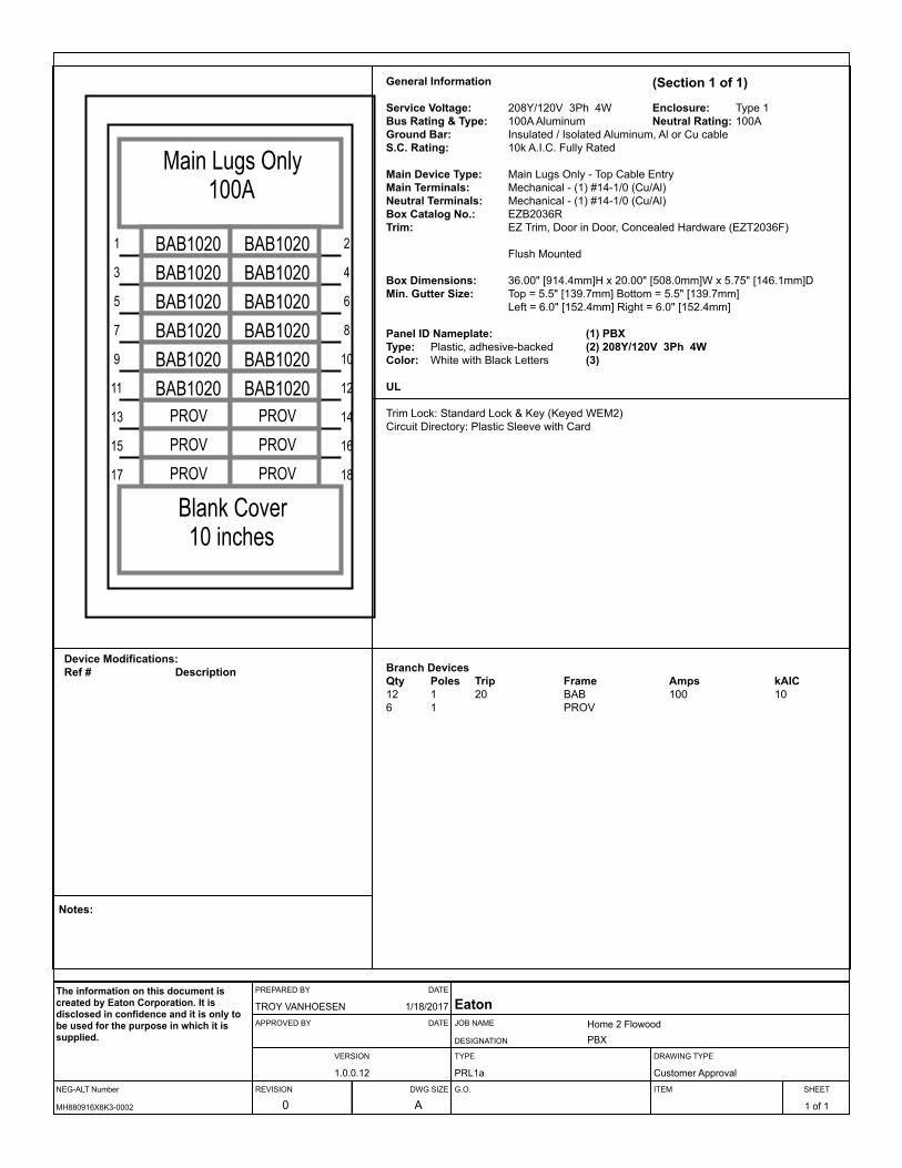
PROV PROV
PROV PROV
PROV PROV
1 2
3 4
5 6
7 8
9 10
11 12
13 14
15 16
17 18
Main Lugs Only100A
BAB1020 BAB1020BAB1020 BAB1020BAB1020 BAB1020BAB1020 BAB1020BAB1020 BAB1020BAB1020 BAB1020
Blank Cover10 inches
General Information (Section 1 of 1)
Service Voltage: 208Y/120V 3Ph 4W Enclosure: Type 1Bus Rating & Type: 100A Aluminum Neutral Rating: 100AGround Bar: Insulated / Isolated Aluminum, Al or Cu cableS.C. Rating: 10k A.I.C. Fully Rated
Main Device Type: Main Lugs Only - Top Cable EntryMain Terminals: Mechanical - (1) #14-1/0 (Cu/Al)Neutral Terminals: Mechanical - (1) #14-1/0 (Cu/Al)Box Catalog No.: EZB2036RTrim: EZ Trim, Door in Door, Concealed Hardware (EZT2036F)
Flush Mounted
Box Dimensions: 36.00" [914.4mm]H x 20.00" [508.0mm]W x 5.75" [146.1mm]DMin. Gutter Size: Top = 5.5" [139.7mm] Bottom = 5.5" [139.7mm]
Left = 6.0" [152.4mm] Right = 6.0" [152.4mm]
Panel ID Nameplate: (1) PBXType: Plastic, adhesive-backed (2) 208Y/120V 3Ph 4WColor: White with Black Letters (3)
UL
Trim Lock: Standard Lock & Key (Keyed WEM2)Circuit Directory: Plastic Sleeve with Card
Branch DevicesQty Poles Trip Frame Amps kAIC12 1 20 BAB 100 106 1 PROV
Device Modifications:Ref # Description
Notes:
NEG-ALT Number
PREPARED BY DATE
APPROVED BY DATE
VERSION
REVISION DWG SIZE
JOB NAME
DESIGNATION
TYPE
G.O.
DRAWING TYPE
ITEM SHEET
The information on this document is created by Eaton Corporation. It is disclosed in confidence and it is only to be used for the purpose in which it is supplied.
MH880916X6K3-0002
TROY VANHOESEN 1/18/2017
1.0.0.12
0 A
EatonHome 2 FlowoodPBX
PRL1a Customer Approval
1 of 1

1 2
3 4
5 6
7 8
9 10
11 12
13 14
15 16
17 18
19 20
21 22
23 24
25 26
27 28
29 30
Blank Cover2 inches
BAB1020 BAB1020BAB1020BAB1020 BAB1020BAB1020 BAB1020BAB1020 BAB1020BAB1020 BAB1020BAB1020BAB1020BAB1020BAB1020 BAB1020BAB1020 BAB1020BAB1020 BAB1020
BAB1030 BAB1030BAB1020
BAB1030
BAB1020 BAB1020
BAB1020
BAB3050H
Main Lugs Only225A
General Information (Section 1 of 1)
Service Voltage: 208Y/120V 3Ph 4W Enclosure: Type 1Bus Rating & Type: 225A Aluminum Neutral Rating: 225AGround Bar: Std. Bolted Aluminum, Al or Cu cableS.C. Rating: 10k A.I.C. Fully Rated
Main Device Type: Main Lugs Only - Bottom Cable EntryMain Terminals: Mechanical - (1) #6-300 kcmil (Cu/Al)Neutral Terminals: Mechanical - (1) #6-300 kcmil (Cu/Al)Box Catalog No.: EZB2036RTrim: EZ Trim, Door in Door, Concealed Hardware (EZT2036S)
Surface Mounted
Box Dimensions: 36.00" [914.4mm]H x 20.00" [508.0mm]W x 5.75" [146.1mm]DMin. Gutter Size: Top = 5.5" [139.7mm] Bottom = 5.5" [139.7mm]
Left = 6.0" [152.4mm] Right = 6.0" [152.4mm]
Panel ID Nameplate: (1) KType: Plastic, adhesive-backed (2) 208Y/120V 3Ph 4WColor: White with Black Letters (3)
UL
Trim Lock: Standard Lock & Key (Keyed WEM2)Circuit Directory: Plastic Sleeve with Card
Branch DevicesQty Poles Trip Frame Amps kAIC3 1 30 BAB 100 101 3 50 BAB 100 1024 1 20 BAB 100 10
Device Modifications:Ref # Description
Notes:
NEG-ALT Number
PREPARED BY DATE
APPROVED BY DATE
VERSION
REVISION DWG SIZE
JOB NAME
DESIGNATION
TYPE
G.O.
DRAWING TYPE
ITEM SHEET
The information on this document is created by Eaton Corporation. It is disclosed in confidence and it is only to be used for the purpose in which it is supplied.
MH880916X6K3-0002
TROY VANHOESEN 1/18/2017
1.0.0.12
0 A
EatonHome 2 FlowoodK
PRL1a Customer Approval
1 of 1

1 2
3 4
5 6
7 8
9 10
11 12
13 14
15 16
17 18
19 20
21 22
23 24
25 26
27 28
29 30
31 32
33 34
35 36
37 38
39 40
41 42
Blank Cover2 inches
BAB3030H BAB3030H
BAB3030H BAB3030H
BAB3030H
BAB1020BAB1020BAB1020
BAB1020BAB1020BAB1020BAB1020 BAB1020BAB1020 BAB1020
BAB2020
BAB3030H
QBGFT1020
BAB3030H
QBGFT1020
BAB1020
BAB1020BAB1020
BAB3040H
BAB1020
Main Lugs Only225A
General Information (Section 1 of 1)
Service Voltage: 208Y/120V 3Ph 4W Enclosure: Type 1Bus Rating & Type: 225A Aluminum Neutral Rating: 225AGround Bar: Std. Bolted Aluminum, Al or Cu cableS.C. Rating: 10k A.I.C. Fully Rated
Main Device Type: Main Lugs Only - Bottom Cable EntryMain Terminals: Mechanical - (1) #6-300 kcmil (Cu/Al)Neutral Terminals: Mechanical - (1) #6-300 kcmil (Cu/Al)Box Catalog No.: EZB2042RTrim: EZ Trim, Door in Door, Concealed Hardware (EZT2042S)
Surface Mounted
Box Dimensions: 42.00" [1066.8mm]H x 20.00" [508.0mm]W x 5.75" [146.1mm]DMin. Gutter Size: Top = 5.5" [139.7mm] Bottom = 5.5" [139.7mm]
Left = 6.0" [152.4mm] Right = 6.0" [152.4mm]
Panel ID Nameplate: (1) LDYType: Plastic, adhesive-backed (2) 208Y/120V 3Ph 4WColor: White with Black Letters (3)
UL
Trim Lock: Standard Lock & Key (Keyed WEM2)Circuit Directory: Plastic Sleeve with Card
Branch DevicesQty Poles Trip Frame Amps kAIC7 3 30 BAB 100 101 3 40 BAB 100 101 2 20 BAB 100 102 1 20 QBGFT 100 1014 1 20 BAB 100 10
Device Modifications:Ref # Description
Notes:
NEG-ALT Number
PREPARED BY DATE
APPROVED BY DATE
VERSION
REVISION DWG SIZE
JOB NAME
DESIGNATION
TYPE
G.O.
DRAWING TYPE
ITEM SHEET
The information on this document is created by Eaton Corporation. It is disclosed in confidence and it is only to be used for the purpose in which it is supplied.
MH880916X6K3-0002
TROY VANHOESEN 1/18/2017
1.0.0.12
0 A
EatonHome 2 FlowoodLDY
PRL1a Customer Approval
1 of 1

1 2
3 4
5 6
7 8
9 10
11 12
13 14
15 16
17 18
19 20
21 22
23 24
25 26
27 28
29 30
31 32
33 34
35 36
37 38
39 40
41 42
Blank Cover3 inches
BAB1020BAB1020BAB1020
BAB2030
BAB1020BAB3040H
BAB2040
BAB2020
BAB2050
BAB1020BAB1020BAB1020BAB1020BAB1020
BAB3015H
BAB3040H
BAB1020BAB3030H
BAB2020
BAB2020
BAB2020
BAB1020
BAB2020
BAB3040H
Main Lugs Only225A
General Information (Section 1 of 1)
Service Voltage: 208Y/120V 3Ph 4W Enclosure: Type 1Bus Rating & Type: 225A Aluminum Neutral Rating: 225AGround Bar: Std. Bolted Aluminum, Al or Cu cableS.C. Rating: 10k A.I.C. Fully Rated
Main Device Type: Main Lugs Only - Bottom Cable EntryMain Terminals: Mechanical - (1) #4-500 kcmil (Cu/Al)Neutral Terminals: Mechanical - (1) #4-500 kcmil (Cu/Al)Box Catalog No.: EZB2048RTrim: EZ Trim, Door in Door, Concealed Hardware (EZT2048S)
Surface Mounted
Box Dimensions: 48.00" [1219.2mm]H x 20.00" [508.0mm]W x 5.75" [146.1mm]DMin. Gutter Size: Top = 5.5" [139.7mm] Bottom = 5.5" [139.7mm]
Left = 6.0" [152.4mm] Right = 6.0" [152.4mm]
Panel ID Nameplate: (1) HACType: Plastic, adhesive-backed (2) 208Y/120V 3Ph 4WColor: White with Black Letters (3)
UL
Trim Lock: Standard Lock & Key (Keyed WEM2)Circuit Directory: Plastic Sleeve with Card
Branch DevicesQty Poles Trip Frame Amps kAIC1 2 30 BAB 100 1011 1 20 BAB 100 103 3 40 BAB 100 101 2 40 BAB 100 101 2 50 BAB 100 101 3 15 BAB 100 105 2 20 BAB 100 101 3 30 BAB 100 10
Device Modifications:Ref # Description
Notes:
NEG-ALT Number
PREPARED BY DATE
APPROVED BY DATE
VERSION
REVISION DWG SIZE
JOB NAME
DESIGNATION
TYPE
G.O.
DRAWING TYPE
ITEM SHEET
The information on this document is created by Eaton Corporation. It is disclosed in confidence and it is only to be used for the purpose in which it is supplied.
MH880916X6K3-0002
TROY VANHOESEN 1/18/2017
1.0.0.12
0 A
EatonHome 2 FlowoodHAC
PRL1a Customer Approval
1 of 1
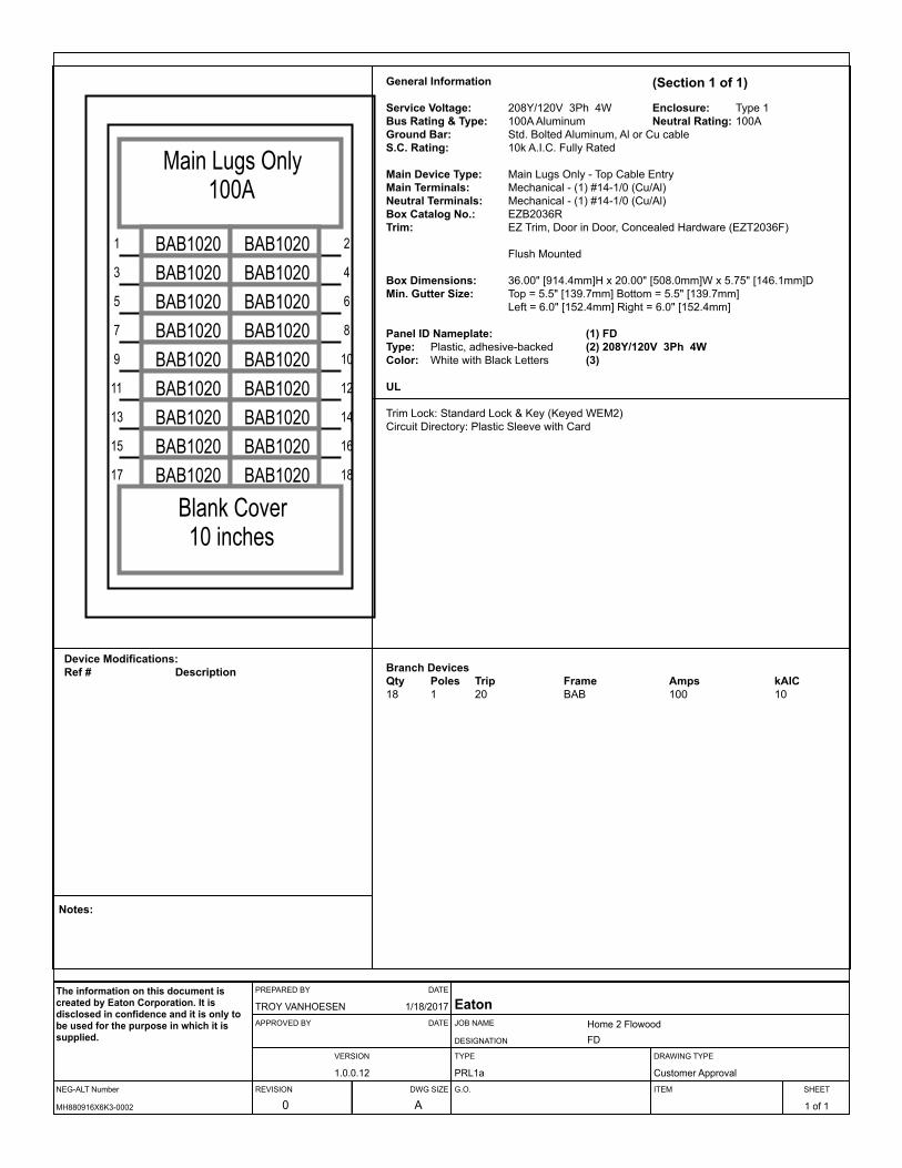
1 2
3 4
5 6
7 8
9 10
11 12
13 14
15 16
17 18
Main Lugs Only100A
BAB1020 BAB1020BAB1020 BAB1020BAB1020 BAB1020BAB1020 BAB1020BAB1020 BAB1020BAB1020 BAB1020BAB1020 BAB1020BAB1020 BAB1020BAB1020 BAB1020
Blank Cover10 inches
General Information (Section 1 of 1)
Service Voltage: 208Y/120V 3Ph 4W Enclosure: Type 1Bus Rating & Type: 100A Aluminum Neutral Rating: 100AGround Bar: Std. Bolted Aluminum, Al or Cu cableS.C. Rating: 10k A.I.C. Fully Rated
Main Device Type: Main Lugs Only - Top Cable EntryMain Terminals: Mechanical - (1) #14-1/0 (Cu/Al)Neutral Terminals: Mechanical - (1) #14-1/0 (Cu/Al)Box Catalog No.: EZB2036RTrim: EZ Trim, Door in Door, Concealed Hardware (EZT2036F)
Flush Mounted
Box Dimensions: 36.00" [914.4mm]H x 20.00" [508.0mm]W x 5.75" [146.1mm]DMin. Gutter Size: Top = 5.5" [139.7mm] Bottom = 5.5" [139.7mm]
Left = 6.0" [152.4mm] Right = 6.0" [152.4mm]
Panel ID Nameplate: (1) FDType: Plastic, adhesive-backed (2) 208Y/120V 3Ph 4WColor: White with Black Letters (3)
UL
Trim Lock: Standard Lock & Key (Keyed WEM2)Circuit Directory: Plastic Sleeve with Card
Branch DevicesQty Poles Trip Frame Amps kAIC18 1 20 BAB 100 10
Device Modifications:Ref # Description
Notes:
NEG-ALT Number
PREPARED BY DATE
APPROVED BY DATE
VERSION
REVISION DWG SIZE
JOB NAME
DESIGNATION
TYPE
G.O.
DRAWING TYPE
ITEM SHEET
The information on this document is created by Eaton Corporation. It is disclosed in confidence and it is only to be used for the purpose in which it is supplied.
MH880916X6K3-0002
TROY VANHOESEN 1/18/2017
1.0.0.12
0 A
EatonHome 2 FlowoodFD
PRL1a Customer Approval
1 of 1

1 2
3 4
5 6
7 8
9 10
11 12
13 14
15 16
17 18
Blank Cover10 inches
BAB2060 QBGFT2020
QBGFT1020
QBGFT1020
QBGFT1020
BAB1020BAB1020 BAB1020BAB1020 BAB1020BAB1020 BAB1020
QBGFT1020
BAB1020
QBGFT1020BAB1020
Main Lugs Only100A
General Information (Section 1 of 1)
Service Voltage: 208Y/120V 3Ph 4W Enclosure: Type 1Bus Rating & Type: 100A Aluminum Neutral Rating: 100AGround Bar: Std. Bolted Aluminum, Al or Cu cableS.C. Rating: 10k A.I.C. Fully Rated
Main Device Type: Main Lugs Only - Bottom Cable EntryMain Terminals: Mechanical - (1) #14-1/0 (Cu/Al)Neutral Terminals: Mechanical - (1) #14-1/0 (Cu/Al)Box Catalog No.: EZB2036RTrim: EZ Trim, Door in Door, Concealed Hardware (EZT2036S)
Surface Mounted
Box Dimensions: 36.00" [914.4mm]H x 20.00" [508.0mm]W x 5.75" [146.1mm]DMin. Gutter Size: Top = 5.5" [139.7mm] Bottom = 5.5" [139.7mm]
Left = 6.0" [152.4mm] Right = 6.0" [152.4mm]
Panel ID Nameplate: (1) PLType: Plastic, adhesive-backed (2) 208Y/120V 3Ph 4WColor: White with Black Letters (3)
UL
Trim Lock: Standard Lock & Key (Keyed WEM2)Circuit Directory: Plastic Sleeve with Card
Branch DevicesQty Poles Trip Frame Amps kAIC9 1 20 BAB 100 105 1 20 QBGFT 100 101 2 60 BAB 100 101 2 20 QBGFT 100 10
Device Modifications:Ref # Description
Notes:
NEG-ALT Number
PREPARED BY DATE
APPROVED BY DATE
VERSION
REVISION DWG SIZE
JOB NAME
DESIGNATION
TYPE
G.O.
DRAWING TYPE
ITEM SHEET
The information on this document is created by Eaton Corporation. It is disclosed in confidence and it is only to be used for the purpose in which it is supplied.
MH880916X6K3-0002
TROY VANHOESEN 1/18/2017
1.0.0.12
0 A
EatonHome 2 FlowoodPL
PRL1a Customer Approval
1 of 1

1 2
3 4
5 6
7 8
9 10
11 12
13 14
15 16
17 18
19 20
21 22
23 24
25 26
27 28
29 30
31 32
33 34
35 36
Bus Cover8X
BAB1020BAB1020BAB1020BAB1020
BAB2020
BAB1020
BAB3025H
BAB1015BAB1015BAB1020
BAB3020H
BAB1020 BAB1020
BAB3030H BAB3030H
FDB3110110A
FDB3110110A
Neutral
Main Lugs Only400A
General Information (Section 1 of 1)
Service Voltage: 208Y/120V 3Ph 4W Enclosure: Type 3RBus Rating & Type: 400A Aluminum Neutral Rating: 400AGround Bar: Std. Bolted Aluminum, Al or Cu cableS.C. Rating: 10k A.I.C. Fully Rated
Main Device Type: Main Lugs Only - Bottom Cable EntryMain Terminals: Mechanical - (2) #4-500 kcmil (Cu/Al)Neutral Terminals: Mechanical - (2) #4-500 kcmil (Cu/Al)Box Catalog No.: LWPQ2072Trim: Complete Enclosure (Includes Trim)
Surface Mounted
Box Dimensions: 72.00" [1828.8mm]H x 20.00" [508.0mm]W x 6.5" [165.1mm]DMin. Gutter Size: Top = 5.5" [139.7mm] Bottom = 5.5" [139.7mm]
Left = 4" [101.6mm] Right = 4" [101.6mm]
Panel ID Nameplate: (1) RFType: Plastic, adhesive-backed (2) 208Y/120V 3Ph 4WColor: White with Black Letters (3)
UL
Trim Lock: T-Handle Lock AssemblyCircuit Directory: Plastic Sleeve with CardPainted Box: ANSI 61
Branch DevicesQty Poles Trip Frame Amps kAIC2 1 15 BAB 100 108 1 20 BAB 100 102 3 30 BAB 100 101 3 20 BAB 100 101 3 25 BAB 100 101 2 20 BAB 100 102 3 110 FDB 150 10
Device Modifications:Ref # Description
Notes:
NEG-ALT Number
PREPARED BY DATE
APPROVED BY DATE
VERSION
REVISION DWG SIZE
JOB NAME
DESIGNATION
TYPE
G.O.
DRAWING TYPE
ITEM SHEET
The information on this document is created by Eaton Corporation. It is disclosed in confidence and it is only to be used for the purpose in which it is supplied.
MH880916X6K3-0002
TROY VANHOESEN 1/18/2017
1.0.0.12
0 A
EatonHome 2 FlowoodRF
PRL3a Customer Approval
1 of 1

1 2
3 4
5 6
7 8
9 10
11 12
13 14
15 16
17 18
19 20
21 22
23 24
25 26
27 28
29 30
Blank Cover2 inches
BAB2100
BAB2100
BAB2100
BAB1020BAB1020BAB1020BAB1020BAB1020BAB1020
BAB1020BAB1020BAB1020 BAB1020BAB1020 BAB1020BAB1020 BAB1020
BAB2100BAB1020BAB1020
BAB2100BAB1020BAB1020
BAB1020BAB1020
Main Lugs Only225A
General Information (Section 1 of 1)
Service Voltage: 208Y/120V 3Ph 4W Enclosure: Type 3RBus Rating & Type: 225A Aluminum Neutral Rating: 225AGround Bar: Std. Bolted Aluminum, Al or Cu cableS.C. Rating: 10k A.I.C. Fully Rated
Main Device Type: Main Lugs Only - Bottom Cable EntryMain Terminals: Mechanical - (1) #6-300 kcmil (Cu/Al)Neutral Terminals: Mechanical - (1) #6-300 kcmil (Cu/Al)Box Catalog No.: LWPQ2036Trim: Complete Enclosure (Includes Trim)
Surface Mounted
Box Dimensions: 36.00" [914.4mm]H x 20.00" [508.0mm]W x 6.5" [165.1mm]DMin. Gutter Size: Top = 5.5" [139.7mm] Bottom = 5.5" [139.7mm]
Left = 6.0" [152.4mm] Right = 6.0" [152.4mm]
Panel ID Nameplate: (1) 2D, 3D, 4D, 5DType: Plastic, adhesive-backed (2) 208Y/120V 3Ph 4WColor: White with Black Letters (3)
UL
Trim Lock: T-Handle Lock AssemblyCircuit Directory: Plastic Sleeve with CardPainted Box: ANSI 61
Branch DevicesQty Poles Trip Frame Amps kAIC5 2 100 BAB 100 1020 1 20 BAB 100 10
Device Modifications:Ref # Description
Notes:
NEG-ALT Number
PREPARED BY DATE
APPROVED BY DATE
VERSION
REVISION DWG SIZE
JOB NAME
DESIGNATION
TYPE
G.O.
DRAWING TYPE
ITEM SHEET
The information on this document is created by Eaton Corporation. It is disclosed in confidence and it is only to be used for the purpose in which it is supplied.
MH880916X6K3-0002
TROY VANHOESEN 1/18/2017
1.0.0.12
0 A
EatonHome 2 Flowood2D, 3D, 4D, 5D
PRL1a Customer Approval
1 of 1

PROV
PROV
PROV
PROV
PROV
PROV
PROV
PROV
PROV PROV
PROV PROV
PROV PROV
PROV PROV
PROV PROV
1 2
3 4
5 6
7 8
9 10
11 12
13 14
15 16
17 18
19 20
21 22
23 24
25 26
27 28
29 30
31 32
33 34
35 36
37 38
39 40
41 42
Blank Cover2 inches
BAB2100
BAB2100
BAB2100
BAB2100
BAB1020BAB1020BAB1020BAB1020BAB1020BAB1020BAB1020BAB1020BAB2100
BAB2100
BAB2100
BAB2100
Main Lugs Only225A
General Information (Section 1 of 1)
Service Voltage: 208Y/120V 3Ph 4W Enclosure: Type 3RBus Rating & Type: 225A Aluminum Neutral Rating: 225AGround Bar: Std. Bolted Aluminum, Al or Cu cableS.C. Rating: 10k A.I.C. Fully Rated
Main Device Type: Main Lugs Only - Bottom Cable EntryMain Terminals: Mechanical - (1) #6-300 kcmil (Cu/Al)Neutral Terminals: Mechanical - (1) #6-300 kcmil (Cu/Al)Box Catalog No.: LWPQ2042Trim: Complete Enclosure (Includes Trim)
Surface Mounted
Box Dimensions: 42.00" [1066.8mm]H x 20.00" [508.0mm]W x 6.5" [165.1mm]DMin. Gutter Size: Top = 5.5" [139.7mm] Bottom = 5.5" [139.7mm]
Left = 6.0" [152.4mm] Right = 6.0" [152.4mm]
Panel ID Nameplate: (1) 2A, 2B, 2C, 3A, 3B, 3C, 4A, 4B, 4C, 5A, 5B, 5C,...Type: Plastic, adhesive-backed (2) 208Y/120V 3Ph 4WColor: White with Black Letters (3)
UL
Trim Lock: T-Handle Lock AssemblyCircuit Directory: Plastic Sleeve with CardPainted Box: ANSI 61
Branch DevicesQty Poles Trip Frame Amps kAIC8 2 100 BAB 100 108 1 20 BAB 100 1018 1 PROV
Device Modifications:Ref # Description
Notes:
NEG-ALT Number
PREPARED BY DATE
APPROVED BY DATE
VERSION
REVISION DWG SIZE
JOB NAME
DESIGNATION
TYPE
G.O.
DRAWING TYPE
ITEM SHEET
The information on this document is created by Eaton Corporation. It is disclosed in confidence and it is only to be used for the purpose in which it is supplied.
MH880916X6K3-0002
TROY VANHOESEN 1/18/2017
1.0.0.12
0 A
EatonHome 2 Flowood2A, 2B, 2C, 3A, 3B, 3C, 4A, 4B, 4C, 5A, 5B, 5C,...
PRL1a Customer Approval
1 of 1

1 2
3 4
5 6
7 8
9 10
11 12
13 14
15 16
17 18
19 20
21 22
23 24
25 26
27 28
29 30
Blank Cover4 inches
BAB1020 BAB1020BAB1020 BAB1020BAB1020 BAB1020BAB1020 BAB1020BAB1020 BAB1020BAB1020 BAB1020BAB1020 BAB1020BAB1020 BAB1020BAB1020 BAB1020BAB1020 BAB1020BAB1020 BAB1020BAB1020 BAB1020BAB1020 BAB1020BAB1020 BAB1020BAB1020 BAB1020
Main Lugs Only100A
General Information (Section 1 of 1)
Service Voltage: 208Y/120V 3Ph 4W Enclosure: Type 1Bus Rating & Type: 100A Aluminum Neutral Rating: 100AGround Bar: Std. Bolted Aluminum, Al or Cu cableS.C. Rating: 10k A.I.C. Fully Rated
Main Device Type: Main Lugs Only - Bottom Cable EntryMain Terminals: Mechanical - (1) #14-1/0 (Cu/Al)Neutral Terminals: Mechanical - (1) #14-1/0 (Cu/Al)Box Catalog No.: EZB2036RTrim: EZ Trim, Door in Door, Concealed Hardware (EZT2036S)
Surface Mounted
Box Dimensions: 36.00" [914.4mm]H x 20.00" [508.0mm]W x 5.75" [146.1mm]DMin. Gutter Size: Top = 5.5" [139.7mm] Bottom = 5.5" [139.7mm]
Left = 6.0" [152.4mm] Right = 6.0" [152.4mm]
Panel ID Nameplate: (1) PHType: Plastic, adhesive-backed (2) 208Y/120V 3Ph 4WColor: White with Black Letters (3)
UL
Trim Lock: Standard Lock & Key (Keyed WEM2)Circuit Directory: Plastic Sleeve with Card
Branch DevicesQty Poles Trip Frame Amps kAIC30 1 20 BAB 100 10
Device Modifications:Ref # Description
Notes:
NEG-ALT Number
PREPARED BY DATE
APPROVED BY DATE
VERSION
REVISION DWG SIZE
JOB NAME
DESIGNATION
TYPE
G.O.
DRAWING TYPE
ITEM SHEET
The information on this document is created by Eaton Corporation. It is disclosed in confidence and it is only to be used for the purpose in which it is supplied.
MH880916X6K3-0002
TROY VANHOESEN 1/18/2017
1.0.0.12
0 A
EatonHome 2 FlowoodPH
PRL1a Customer Approval
1 of 1

Volume 2—Commercial Distribution CA08100003E—April 2014 www.eaton.com V2-T3-7
3
3.3Panelboards and Lighting Control
Pow-R-Line C Panelboards
Pow-R-Line C Panelboards
Product DescriptionLighting and Distribution PanelboardsEaton’s assembled panelboards are designed for sequence phase connection of branch circuit devices. This allows complete flexibility of circuit arrangement (single-, two- or three-pole) to allow balance of the electrical load on each phase.
Sturdy, rigid chassis assembly ensures accurate alignment of interior with panel front; prevents flexing and minimizes possibility of loosening or damage to current carrying parts during and after installation.
Four-point in-and-out adjustment of panel interioris provided to meet critical depth dimensions on flush installations. This compensates for possible misalignment of box at installation.
Main lugs are mechanical solderless type and approved for copper or aluminum conductors.
EnclosuresBoxes are code-gauge galvanized steel, which include a painted box finished in ANSI-61 light gray to match the trim.
Standard panelboard cabinets are designed for indoor use. Alternate types are available for indoor and special purpose applications.
All enclosures are furnished in accordance with Underwriters Laboratories standards and include wiring gutters with proper wire bending space. Special cabinets can be provided at an additional charge.
The box dimensions shown are inside dimensions. For outside dimensions, add 1/4-inch (6.4 mm).
Standard panelboard boxes are supplied without knockouts (blank endwalls).
FrontsFronts (trims) for all panelboards are made of code-gauge steel and have a high durability ANSI-61 light gray finish applied by a baked-on polyester powder coating paint system.
The fronts for lighting and appliance branch circuit panelboards and small power distribution panelboards include a door with rounded corners and concealed hinges. A flush-type latch and lock assembly is included. All locks are keyed alike. These trims are available in both surface- and flush-mounted designs.
EZ Trim Features Standard Door-in-Door with No Exposed Hardware or
Sharp Edges (no Tools are Required for Installation)
The Three-Piece Trim for Larger Power Distribution Panelboards Provides for
Easy Handling and Installation
Fronts for power distribution panelboards utilize a unique breaker front cover design in which each device has a dedicated bolt-on steel cover. The individual covers form a single deadfront for the panelboard that is used in conjunction with two wiring gutter covers to complete the trim. A door is not finished as part of the standard offering on these panelboards but can be provided, for an additional charge, using a deeper than standard box.

V2-T3-8 Volume 2—Commercial Distribution CA08100003E—April 2014 www.eaton.com
3
3.3 Panelboards and Lighting Control
Pow-R-Line C Panelboards
Application DescriptionPanelboard Selection FactorsIn selecting a panelboard, the following factors must be considered:
● Service (voltage andfrequency)
● Interrupting capacity(fully or series rated)
● Ampere rating of main● Ampere ratings of
branches● Environment
Panelboard Short-Circuit RatingThe short-circuit rating of Eaton’s assembled panelboards are test verified by, and listed with, Underwriters Laboratories (UL). Generally, these ratings are that of the lowest interrupting rated device in the panel.
Certain exceptions to this rule exist where branch devices have been UL tested in combination with specific main devices having a higher interrupting rating. Where these defined main devices and branch breaker combinations are utilized, the series short-circuit rating of the assembled panelboard will be the same as the tested rating of the approved rated main device in series with the branches. Available main and branch breaker combinations are tabulated starting on Page V2-T3-16. All combinations shown are UL tested and listed.
These series ratings apply to panels having main devices, or main lug only panelboards fed remotely by the device listed in the series ratings chart as the main, for which UL listed tests were conducted.
Service Entrance EquipmentThe National Electrical Code (NEC) requires that:
● A panel used as serviceentrance equipmentmust be located nearthe point where thesupply conductors enterthe building
● A panelboard having mainlugs only shall have amaximum of six servicedisconnects to de-energizethe entire panelboard fromthe supply conductors.Where more than sixdisconnects are required,a main service disconnectmust be provided
● A disconnectable electricalbond must be providedbetween the neutral andground
● A service entrance typeUL label must be factoryinstalled
● Ground fault protectionof equipment shall beprovided for each servicedisconnect rated 1000Aor more if the electricalservice is a solidlygrounded wye system ofmore than 150V to ground,but not exceeding 600Vphase-to-phase
Note: Service entrance panels must be identified as such on the order.
Panelboard StandardsIn 2008, both the National Electrical Code (Article 408) and UL 67 were updated to remove the mandated 42-circuit limitation. Eaton offers panelboards with more than 42 circuits for those jurisdictions that have adopted the 2008 NEC or later.
For jurisdictions that have| not adopted the 2008 or later version of the National Electrical Code, the 42-circuit limitation for Lighting and Appliance Branch Panelboards remains in place. Check with your local code officials to determine specific jurisdiction status.
Panelboard InstallationNEC requires that the operating handle of the topmost mounted device be no more than 6 feet 7 inches (2006.6 mm) above the finished floor and should be installed per NEC and manufacturer’s instructions.
Additional boxes and fronts are required when the components required for one panelboard exceed the standard box dimensions.
Multi-Section PanelboardsWhen two or more separate enclosures are required, separate fronts for each box are standard. A common front can be furnished at additional charge.
Interconnecting Multi-Section PanelboardsWhen a panelboard, for connection to one feeder, must be furnished in more than one section (Box), each section must be furnished with main bus and terminals of the same rating, unless a main overcurrent device is provided in each section.
Sub-feed or through-feed provisions must also be included (and priced) to provide connection capability to the second section.
Note: Sub-feed or through-feed lugs cannot be used on any panelboard that is not protected by a single main overcurrent device either in the panelboard or immediately upstream, i.e., service entrance panelboards with main lugs only using the six disconnect rule.
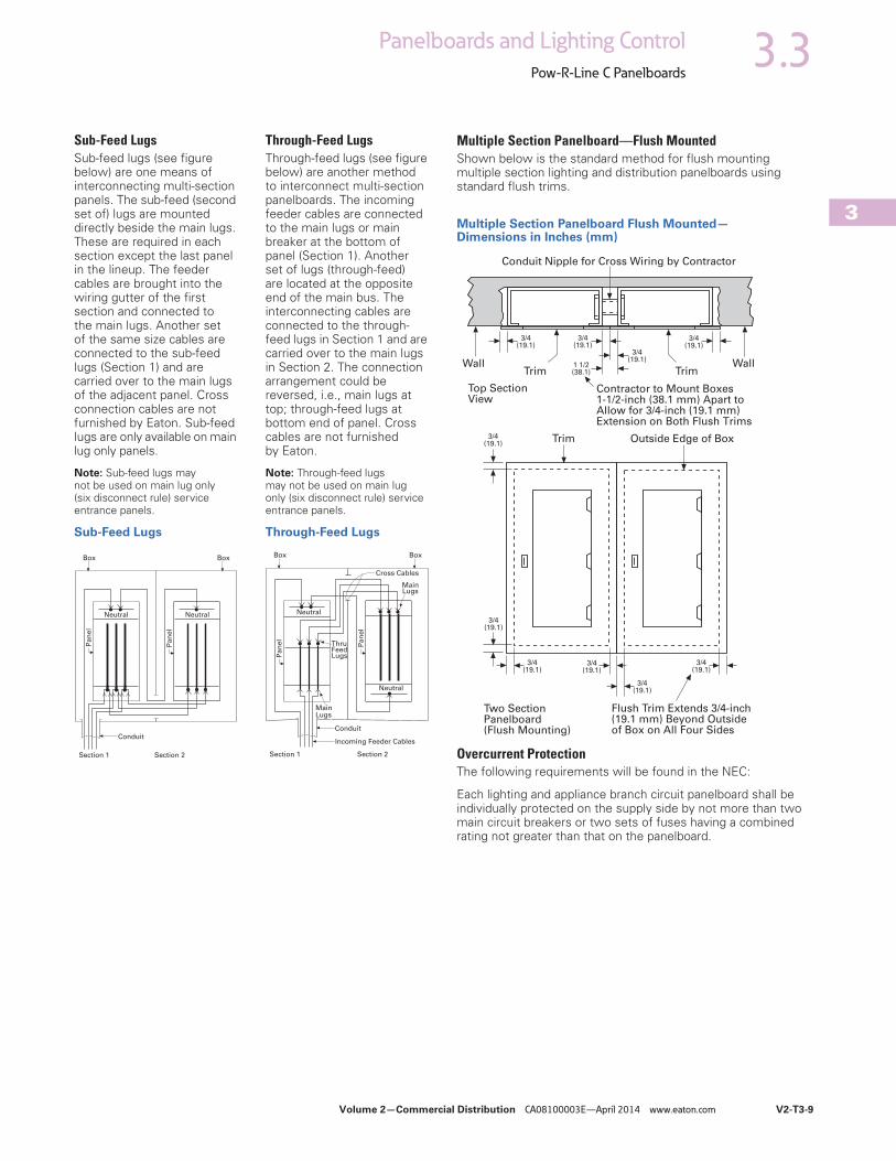
Volume 2—Commercial Distribution CA08100003E—April 2014 www.eaton.com V2-T3-9
3
3.3Panelboards and Lighting Control
Pow-R-Line C Panelboards
Sub-Feed LugsSub-feed lugs (see figure below) are one means of interconnecting multi-section panels. The sub-feed (second set of) lugs are mounted directly beside the main lugs. These are required in each section except the last panel in the lineup. The feeder cables are brought into the wiring gutter of the first section and connected to the main lugs. Another set of the same size cables are connected to the sub-feed lugs (Section 1) and are carried over to the main lugs of the adjacent panel. Cross connection cables are not furnished by Eaton. Sub-feed lugs are only available on main lug only panels.
Note: Sub-feed lugs may not be used on main lug only (six disconnect rule) service entrance panels.
Sub-Feed Lugs
Through-Feed LugsThrough-feed lugs (see figure below) are another method to interconnect multi-section panelboards. The incoming feeder cables are connected to the main lugs or main breaker at the bottom of panel (Section 1). Another set of lugs (through-feed) are located at the opposite end of the main bus. The interconnecting cables are connected to the through-feed lugs in Section 1 and are carried over to the main lugs in Section 2. The connection arrangement could be reversed, i.e., main lugs at top; through-feed lugs at bottom end of panel. Cross cables are not furnished by Eaton.
Note: Through-feed lugs may not be used on main lug only (six disconnect rule) service entrance panels.
Through-Feed Lugs
Box Box
Conduit
Neutral Neutral
Pan
el
Pan
el
Section 1 Section 2 Section 1 Section 2
Box Box
Conduit
Neutral
Pa
ne
l
Pa
ne
l
Neutral
MainLugs
ThruFeedLugs
MainLugs
Cross Cables
Incoming Feeder Cables
Multiple Section Panelboard—Flush MountedShown below is the standard method for flush mounting multiple section lighting and distribution panelboards using standard flush trims.
Multiple Section Panelboard Flush Mounted—Dimensions in Inches (mm)
Overcurrent ProtectionThe following requirements will be found in the NEC:
Each lighting and appliance branch circuit panelboard shall be individually protected on the supply side by not more than two main circuit breakers or two sets of fuses having a combined rating not greater than that on the panelboard.
Contractor to Mount Boxes1-1/2-inch (38.1 mm) Apart toAllow for 3/4-inch (19.1 mm)Extension on Both Flush Trims
Two SectionPanelboard(Flush Mounting)
Flush Trim Extends 3/4-inch(19.1 mm) Beyond Outsideof Box on All Four Sides
Outside Edge of BoxTrim
Wall WallTrim Trim
Conduit Nipple for Cross Wiring by Contractor
3/4(19.1)
3/4(19.1)
1 1/2(38.1)
Top SectionView
3/4(19.1)
3/4(19.1)
3/4(19.1)
3/4(19.1)
3/4(19.1)
3/4(19.1)
3/4(19.1)
3/4(19.1)
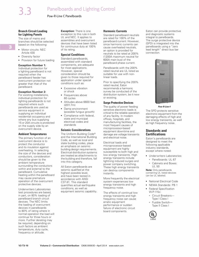
V2-T3-10 Volume 2—Commercial Distribution CA08100003E—April 2014 www.eaton.com
3
3.3 Panelboards and Lighting Control
Pow-R-Line C Panelboards
Branch Circuit Loading for Lighting PanelsThe size of mains and branches should be selected based on the following:
● Motor circuits: NECArticle 430
● Diversity factor● Provision for future loading
Exception Number 1: Individual protection for a lighting panelboard is not required when the panelboard feeder has overcurrent protection not greater than that of the panelboard.
Exception Number 2: For existing installations, individual protection for lighting panelboards is not required where such panelboards are used as service equipment in supplying an individual residential occupancy and where any bus supplying 15 or 20A circuits is protected on the supply side by an overcurrent device.
Ambient TemperaturesThe primary function of an overcurrent device is to protect the conductor and its insulation against overheating. In selecting the size of the devices and conductors, consideration should be given to the ambient temperature surrounding the conductors within and external to the panelboard. Cumulative heating within the panelboard may cause premature operation of the overcurrent protective devices.
Underwriters Laboratories test procedures are based, in part, on 80% loading of panelboard branch circuit devices. The NEC limits the loading of overcurrent devices in panelboards to 80% of rating where in normal operation the load will continue for three hours or more. Further derating may be required, depending on such factors as ambient temperature, duty cycle, frequency or altitude.
Exception: There is one exception to this rule in both UL and NEC. It applies to assemblies and overcurrent devices that have been listed for continuous duty at 100% of its rating.
Special ConditionsStandard panelboards, assembled with standard components, are adequate for most applications. However, special consideration should be given to those required for application under special conditions such as:
● Excessive vibrationor shock
● Frequencies above60 cycles
● Altitudes above 6600 feet(2011.7m)
● Damp environment(possible fungus growth)
● Compliance with federal,state and municipalelectrical codes andstandards
Seismic ConsiderationsThe Uniform Building Code® and the International Building Code, as well as local and state building codes, place an emphasis on seismic building design requirements. Electrical distribution systems are treated as attachments to the building and therefore, fall into this category.
All Eaton panelboards are seismic qualified at the highest possible level, and have been tested in accordance with ANSI C37.81. This standard quantifies actual earthquake conditions, as well as equipment seismic capability.
Harmonic CurrentsStandard panelboard neutrals are rated for 100% of the panelboard current. However, since harmonic currents can cause overheated neutrals, an option is provided for neutrals to be rated at 200% (1200A maximum neutral for 600A main bus) of the panelboard phase current.
Panelboards with the 200% rated neutral are UL listed as suitable for use with non-linear loads.
Prior to specifying the 200% rated neutral, Eaton recommends a harmonic survey be conducted of the distribution system, be it new or existing.
Surge Protective DevicesThe quality of power feeding sensitive electronic loads is critical to the reliable operation of any facility. In modern offices, hospitals, and manufacturing facilities, the most frequent causes of microprocessor-based equipment downtime and damage are voltage transients and electrical noise.
Electrical loads and microprocessor-based equipment are highly susceptible to both high and low energy transients. High energy transients include lightning induced surges and power company switching. These high energy transients can destroy components instantly.
More frequently the electrical system experiences low energy transients and high frequency noise.
The effects of continual low energy transients and high frequency noise can cause erratic equipment performance or sudden failure of electronic circuit board components.
Eaton can provide protective and diagnostic systems integral to panelboards. The surge protective device (SPD) is integrated into the panelboards using a “zero lead length” direct bus bar connection.
Pow-R-Line 4
The SPD protects sensitive electronic equipment from the damaging effects of high and low energy transients, as well as high frequency noise.
Standards and CertificationsEaton’s panelboards are designed to meet the following applicable industry standards, except where noted:
● Underwriters Laboratories:● Panelboards: UL 67● Cabinets and Boxes:
UL 50Note: Only panelboards containing UL listed devices can be UL labeled.
● National Electrical Code● NEMA Standards: PB 1● Federal Specification
W-P-115c:● Circuit Breakers—
Type I Class I● Fusible Switch—
Type II Class I

Volume 2—Commercial Distribution CA08100003E—April 2014 www.eaton.com V2-T3-11
3
3.3Panelboards and Lighting Control
Pow-R-Line C Panelboards
Technical Data and Specifications
Panelboard Selection Guide
Note1 Fixed mounted only.
MaximumVoltage Rating
Maximum MainRating (Amperes)
AC Interrupting Capacityrms Symmetrical Amperes (kA)
PanelboardType
DeviceType AC DC MLO Main Device
Branch CircuitsAmpere Range
Sub-Feed BreakerMaximum Amperes Fully Rated Series Rated
PRL1a Breaker 240 — 400 400 15–100 400 10–22 22–100
PRL1R Breaker 240 — 225 225 15–100 — 10–22 22–100
PRL1aF Fusible 240 — 400 400 15–30 400 200 —
PRL1a-LX Breaker 240 — 225 225 15–100 — 10–22 22–100
PRL2a Breaker 240 250 400 400 15–100 400 65 65–200
Breaker 480Y/277 250 400 400 15–100 400 14 22–150
PRL2R Breaker 240 — 225 225 15–100 — 10–22 22–200
Breaker 480Y/277 — 225 225 15–100 — 14 22–100
PRL2aF Fusible 480Y/277 — 400 400 15–30 400 200 —
PRL2a-LX Breaker 240 250 225 225 15–100 — 65 65–200
Breaker 480Y/277 250 225 225 15–100 — 14 22–150
PRL3a Breaker 240 250 800 600 15–225 600 10–200 22–200
Breaker 480 250 800 600 15–225 600 14–100 22–150
Breaker 600 250 800 600 15–225 600 14–35 —
PRL3E Breaker 240 250 600 600 15–125 400 25–100 100–200
Breaker 480Y/277 250 600 600 15–125 400 18–65 65–100
Breaker 480 250 600 600 15–125 400 18–65 65–100
PRL4B Breaker 240 600 1200 1200 15–1200 — 10–200 22–200
Breaker 480 600 1200 1200 15–1200 — 14–200 22–150
Breaker 600 600 1200 1200 15–1200 — 14–200 —
PRL4D Breaker 240 — 1200 1200 1 600 — 65–200 —
Breaker 480 — 1200 1200 1 600 — 35–100 —
Breaker 600 — 1200 1200 1 600 — 18–50 —
PRL4F Fusible 240 250 1200 1200 30–1200 — 100–200 —
Fusible 600 250 1200 1200 30–1200 — 100–200 —
PRL5P Breaker 240 250 1200 1200 15–1200 — 10–200 22–200
Breaker 480 250 1200 1200 15–1200 — 14–200 22–150
Breaker 600 250 1200 1200 15–1200 — 14–200 —
PRC100 PRC25 Breaker 240 — 400 400 15–225 — 10–65 22–100
Breaker 480Y/277 — 400 400 15–225 — 14 65–100
Elevator Control Fusible 240 — 800 800 15–200 — 200 —
Fusible 480Y/277 — 800 800 15–200 — 200 —
Fusible 480 — 800 800 15–200 — 200 —
Terminal Wire Ranges, Pressure-Type Al/Cu Terminals Except as NotedNote: All terminal sizes are based on wire ampacities corresponding to those shown in NEC Table 310.16 under the 75°C insulation columns (75°C wire). The use of smaller size, (in circular mills), regardless of insulation temperature rating, is not permitted.
Where copper-aluminum terminals are supplied on designated panelboard types, best results are obtained if a suitable joint compound is applied when aluminum conductors are used.
Check Eaton’s standard terminal sizes versus customer requirements. In particular, 400 and 800A breakers often require nonstandard lugs.
Optional 750 kcmil mechanical screw-type terminals are available upon request. Panelboard dimensions may be affected, refer to Eaton.

Volume 2—Commercial Distribution CA08100003E—April 2014 www.eaton.com V2-T3-13
3
3.3Panelboards and Lighting Control
Pow-R-Line C Panelboards
Standard Circuit Breaker Terminals
Breaker Type Ampere Rating Wire Range
BAB, QBHW, BABRSP,HQP, QPHW
15–70 #14–#4
90–100 #8–1/0
EDB, EDS, ED, EDH, EDC 100–225 #4–4/0 or #6–300 kcmil
EGB, EGE, EGS, EGH 15–50 #14–3/0 AL/CU
60–125 #6–3/0 AL/CU
EHD, FDB, FD, HFD, FDC, HFDDC 2
15–100 #14–1/0
125–225 #4–4/0
FCL 15–100 #14–1/0
GHB, HGHB, GHQ, GHQRSP
15–20 #14–#10
25–100 #10–1/0
EGB, EGS, EGH 15–50 #14–1/0
60–125 #6–2/0
JD, HJD, JDC, HJDDC 2 70–250 #4–350 kcmil
DK 250–350 250–500 kcmil
400 (2) 3/0–250 kcmil or (1) 3/0–500 kcmil
KD, HKD, KDC, HKDDC, 2CKD, CHKD
225 (1) #3–350 kcmil
350 (2) 3/0–250 kcmil or
400 (2) 3/0–250 kcmil or (1) 3/0–500 kcmil
LHH 150–400 #2–500 kcmil
150–400 (2) #2–500 kcmil
150–400 (1) 500–750 kcmil
LGE, LGH, LGC, LGU, LHH 1
250–400 (1) #2–500 kcmil
500–600 (2) #2–500 kcmil
LD, HLD, LDC, HLDDC 2CLD, CHLD
300–500 (2) 250–350 kcmil
600 (2) 400–500 kcmil
MDL, HMDL, HMDLDC 2CMDL, CHMDL
400–600 (2) #1–500 kcmil
700–800 (3) 3/0–400 kcmil
ND, HND, CND, CHND, NDC, CNDC
800–1000 (3) 3/0–400 kcmil
1200 (4) 4/0–500 kcmil
LCL 125–225 (1) #6–350 kcmil
250–400 (1) #4–250 kcmil and (1) 3/0–600 kcmil
FB-P 15–100 #14–1/0
LA-P 70–225 #6–350 kcmil
250–400 (1) #4–250 kcmil and (1) 3/0–600 kcmil
NB-P, NBDC 2 300–700 (2) #1–500 kcmil
800 (3) 3/0–400 kcmil
FDPW Switch Terminals
Elevator Control Panel Feeder Terminals
Notes1 LHH is 400A maximum.2 Suitable for DC applications only.
Ampere Rating Wire Range
30 #14–1/0
60 #14–1/0
100 #14–1/0
200 #4–300 kcmil
400 250–750 kcmil or (2) 3/0–250 kcmil
600 (2) #4–600 kcmil or (4) 3/0–250 kcmil
800 (3) 250–750 kcmil or (6) 3/0–250 kcmil
1200 (4) 250–750 kcmil or (8) 3/0–250 kcmil
Ampere Rating Wire Range
30 #14–1/0
60 #14–1/0
100 #14–1/0
200 #4–300 kcmil


Detail Bill of Material Page 1 of 1
Project Name: Home 2 Flowood Negotiation No: MH880916X6K3 General Order No:
Alternate No: 0002
Item No. Qty Product Description 1 Enclosed Controls ECL03F1A3A, Lighting, NEMA 1 - General Purpose, HP, 208V,
Size 200A, Drawing Number: 84-28715, LIST OF MATERIAL:, ECL03F1A3A - Lighting, Electrically Held
Catalog No ECL03F1A3A Designation 200-3
Eaton Selling Policy None applies.
All orders must be released for manufacture within 90 days of date of order entry. If approval drawings are required, drawings must be returned
approved for release within 60 days of mailing. If drawings are not returned accordingly, and/or if shipment is delayed for any reason, the price of the
order will increase by 1.0% per month or fraction there of for the time the shipment is delayed.

1
1
2
2
A A
B B
Page: 1 of 1
GO/NEG-Alt-Date: Job Name:
Item Number: Catalog Number: Designation:
MH880916X6K3-0002-1/18/2017 Home 2 Flowood
ECL03F1A3A 200-3

V10-T4-2 Volume 10—Enclosed Control CA08100012E—June 2015 www.eaton.com
4
4.1 Lighting Contactors
UL Rated AC Contactors
UL Rated AC Contactors
Product DescriptionEaton’s lighting contactors are designed to provide a safe, convenient means for local or remote switching of tungsten (incandescent filament) or ballast (fluorescent and mercury arc) lamp loads. They are also suitable for other loads such as low pressure and high pressure sodium lamp loads and other non-motor (resistive) loads. They are not recommended for most sign flashing loads.
These lighting contactors are designed to withstand the large initial inrush currents of tungsten lamp loads without contact welding. They are fully rated and do not require derating.
Application DescriptionLoads:
Ballast Lamps—Fluorescent, mercury vapor, metal halide sodium vapor, quartz—600 V maximum.
Filament Lamps—Incandescent, infrared, heating—480 V maximum, line to line; 277 V maximum line to neutral.
Resistance Heating—Radiant and convection heating, furnaces and ovens.
Additional ReferenceAccessories . . . . . . . . . . . . . . . . . . . . . . V10-T4-13 and Tab 15
Cover Control . . . . . . . . . . . . . . . . . . . . . . . . . . . . . V10-T4-4
Dimensions . . . . . . . . . . . . . . . . . . . . . . . . . . . . . . Tab 14
Accessories and Modifications . . . . . . . . . . . . . . . Tab 15
Technical Data and Specifications . . . . . . . . . . . . . Tab 17
Standards and CertificationsNote: See Tab 17 for additional information on Standards and Certifications that apply to all Enclosed Control products.
● UL Listed● cUL Listed● ABS Type Approved● OSHPD Certified
(OSP-0015-10)

Volume 10—Enclosed Control CA08100012E—June 2015 www.eaton.com V10-T4-3
4
4.1Lighting Contactors
UL Rated AC Contactors
Catalog Number Selection
Enclosed Lighting Contactors
EnclosuresLighting contactors are available open or mounted in Type 1, 3R, 4, 4X, 12 or 7/9 enclosures.
Type 1 is for indoor, general purpose for personal protection. Knock-outs are provided in the top and bottom for conduit entry.
Type 3R is for outdoor applications and rated for rain, sleet and external ice buildup. Type 3R enclosures have knockouts in the bottom and provisions for a hub in the top.
Type 4 and 4X are for mounting indoor or outdoor and provide protection from splashing water, hose-directed water and wind-blown dust. Watertight conduit hubs are provided in the top and bottom of Type 4X enclosures. The standard Type 4X enclosures are made of 304-Grade stainless steel, providing corrosion protection. 316-Grade stainless steel construction is available as an upgrade option.
Type 12 enclosures are for indoor mounting and protect from dripping liquids, falling dirt and dust. No knockouts or hubs are provided with Type 12 enclosures.
Type 1, 3R, 4 and 12 enclosures are painted with a polyester urethane powder coat paint meeting UL requirements and the color is ANSI 61 gray. Type 1 enclosures have knockouts for cover controls. All the other types have holes plugged, ready for cover controls. Type 7/9 is also available for explosion proof applications. Please contact the factory for additional details.
Notes1 C30CN available in 30 A only.2 For normally closed poles see Tab 15.
Design
L = CN35 or A202 lighting contactorC = C30CN lighting contactor
Class Page
03 = Non-combination electrically held lighting contactor V10-T4-6, V10-T4-7
04 = Non-combination mechanically held/magnetically latched lighting contactor
V10-T4-6,V10-T4-9
12 = Combination electrically held lighting contactor—fusible disconnect
V10-T4-11
13 = Combination magnetically latched lighting contactor—fusible disconnect
V10-T4-11
14 = Combination electrically held lighting contactor—thermal magnetic circuit breaker
V10-T4-12
15 = Combination magnetically latched lighting contactor—thermal magnetic circuit breaker
V10-T4-12
Ampere Size 1
A = 10 AB = 20 AC = 30 A
D = 60 AE = 100 AF = 200 A
G = 300 AH = 400 AJ = 600 A
Modification Codes
(See Pages V10-T4-4 and V10-T4-5 and Tab 15)
Enclosure Types
1 = Type 1—General purpose2 = Type 3R—Rainproof3 = Type 4—Watertight (painted)4 = Type 4X—Watertight (304-Grade stainless steel)6 = Type 7/9—Explosion proof8 = Type 12—Dust-tight9 = Type 4X—Watertight (316-Grade stainless steel)
Disconnect Fuse Clip Ratings
A = NoneB = 30 A / 250 V RC = 30 A / 600 V RD = 60 A / 250 V RE = 30 A / 600 V RF = 100 A / 250 V RG = 100 A / 600 V RH = 200 A / 250 V R
J = 200 A / 600 V RK = 400 A / 250 V RL = 400 A / 600 V RM = 600 A / 250 V RN = 600 A / 600 V RP = 800 A / 600 V RT = By description
Thermal-Magnetic Breaker Ratings
A = NoneD = 20 AE = 30 A
F = 60 AG = 100 AH = 200 A
J = 300 AK = 400 AL = 600 A
M = 800 AT = By description
Number of Poles 2
1, 2, 3, 4, 5, 6, 7, 8, 9 = Poles requiredA = 10 polesB = 12 polesC = 20 polesCombination Devices = Three-pole only
Coil Voltage
A = 120/60 110/50B = 240/60 220/50C = 480/60 440/50D = 600/60 550/50E = 208/60G = 550/50H = 277/60J = 208–240/60
K = 240/50L = 380/50M = 415/50P = 12 VdcQ = 24 VdcR = 48 VdcS = 125 Vdc
T = 24/60U = 24/50V = 32/50W = 48/60X = 104–120/60Y = 48/50Z = By description
EC L 12 D 1 A 3 E - X

Volume 10—Enclosed Control CA08100012E—June 2015 www.eaton.com V10-T4-5
4
4.1Lighting Contactors
UL Rated AC Contactors
Type 1, 3R, 4X and 12 Cover Control Non-Combination (Non-Box 1) and Combination Cover Control
Notes1 For use with non-combination units (box sizes 2–4).2 Add code letter from table below to catalog number for voltage in place of _.
3 Selector switch.4 With three-position selector switch, Mod C20 (two-wire control relay) must be used with magnetically latched contactor (ECL04, ECL13, ECL15).
DescriptionFor Use with Lighting Contactor
Factory Installed Cover Control Field Installation Kits
Type 1, 3R, 4X and 12 Type 7/9 Type 1 12
Type 3R, 4X and 12 Non-Combination and Type 1, 3R, 4X and 12 Combination 2
Modification Code Suffix
Modification Code Suffix
Catalog Number
Catalog Number
ON/OFF pushbuttons Electrical three-wire C30CN; CN35; A202
P8 P8 C400GK18 C400T2
With red RUN pilot light P8P23 P8P23 C400GK19_ —
With red RUN/GREEN off lights P8P23P25 P8P23P25 C400GK1A_ —
ON/OFF Pushbuttons Mechanical three-wire C30CN
P8 P8 C400GK4 C400T201
With red RUN pilot light P8P23 P8P23 C400GK48_ —
With red RUN/GREEN off lights P8P23P25 P8P23P25 C400GK49_ —
ON/OFF pushbuttons Electrical and mechanical two-wire C30CN; CN35; A202
P8 P8 C400GK5 C400T14 3
With red RUN pilot light P8P23 P8P23 C400GK52_ —
With red RUN/GREEN off lights P8P23P25 P8P23P25 C400GK55_ —
Start/stop pushbuttons Mechanical three-wire C30CN
P7 P7 C400GK7 C400T200
With red RUN pilot light P7P23 P7P23 C400GK72_ —
With red RUN/GREEN off lights P7P23P25 P7P23P25 C400GK75_ —
Start/stop pushbuttons Electrical and mechanical two-wire C30CN
P7 P7 C400GK6 C400T13 3
With red RUN pilot light P7P23 P7P23 C400GK62_ —
With red RUN/GREEN off lights P7P23P25 P7P23P25 C400GK65_ —
HAND/OFF/AUTO cover control Electrical and mechanical two-wire C30CN; CN35; A202
S3 S3 4 C400GK3 C400T12 3
With red RUN pilot light S3P23 S3P23 4 C400GK32_ —
With red RUN/GREEN off lights S3P23P25 S3P23P25 4 C400GK35_ —
Red RUN pilot light All P23 P23 C400GK42_ C400T9_
Green OFF pilot light P25 P25 C400GK41_ C400T10_
Red RUN/green OFF pilot light P23P25 P23P25 C400GK46_ C400T11_
Rating Code Letter Rating Code Letter Rating Code Letter
24 V 60 Hz T 240 V 60 Hz B 480 V 60 Hz C
120 V 60 Hz A 277 V 60 Hz H 600 V 60 Hz D
208 V 60 Hz E 380 V 60 Hz L

Volume 10—Enclosed Control CA08100012E—June 2015 www.eaton.com V10-T4-7
4
4.1Lighting Contactors
UL Rated AC Contactors
Class ECL03—Non-Combination Electrically Held Lighting Contactor
Notes1 For open position (coil voltage), use the table below:
2 The catalog numbers listed in the Type 4X column are for Type 4X 304-Grade stainless steel, as indicated by the seventh digit. Example: ECL03B4A2A. To order Type 4X 316-Grade stainless steel, change that digit to 9. To order Type 4 painted steel, change that digit to 3. To order non-metallic, change that digit to 5. For details on these alternate enclosures, see Tab 13.
3 Ampere ratings are based on a maximum load voltage of 480 V for tungsten lamp applications and 600 V for ballast or mercury vapor type applications.
No. of Poles
FrameSize
Type 1GeneralPurpose
Type 3RRainproof
Type 4X 2Watertight andDust-TightStainless Steel
Type 7/9HazardousLocation
Type 12Dust-TightIndustrial
ComponentContactor(Open)
Catalog Number 1 Catalog Number 1 Catalog Number 1 Catalog Number 1 Catalog Number 1 Catalog Number 1
Maximum Ampere Rating—10 3
2 45 mm ECL03A1_2A ECL03A2_2A ECL03A4_2A ECL03A6_2A ECL03A8_2A CN35AN2_B
3 ECL03A1_3A ECL03A2_3A ECL03A4_3A ECL03A6_3A ECL03A8_3A CN35AN3_B
4 ECL03A1_4A ECL03A2_4A ECL03A4_4A ECL03A6_4A ECL03A8_4A CN35AN4_B
5 ECL03A1_5A ECL03A2_5A ECL03A4_5A ECL03A6_5A ECL03A8_5A —
6 ECL03A1_6A ECL03A2_6A ECL03A4_6A ECL03A6_6A ECL03A8_6A —
9 ECL03A1_9A ECL03A2_9A ECL03A4_9A ECL03A6_9A ECL03A8_9A —
10 ECL03A1_AA ECL03A2_AA ECL03A4_AA ECL03A6_AA ECL03A8_AA —
12 ECL03A1_BA ECL03A2_BA ECL03A4_BA ECL03A6_BA ECL03A8_BA —
20 ECL03A1_CA ECL03A2_CA ECL03A4_CA ECL03A6_CA ECL03A8_CA —
Maximum Ampere Rating—20 3
2 45 mm ECL03B1_2A ECL03B2_2A ECL03B4_2A ECL03B6_2A ECL03B8_2A CN35BN2_B
3 ECL03B1_3A ECL03B2_3A ECL03B4_3A ECL03B6_3A ECL03B8_3A CN35BN3_B
4 ECL03B1_4A ECL03B2_4A ECL03B4_4A ECL03B6_4A ECL03B8_4A CN35BN4_B
5 ECL03B1_5A ECL03B2_5A ECL03B4_5A ECL03B6_5A ECL03B8_5A —
6 ECL03B1_6A ECL03B2_6A ECL03B4_6A ECL03B6_6A ECL03B8_6A CN35BN6_B
9 ECL03B1_9A ECL03B2_9A ECL03B4_9A ECL03B6_9A ECL03B8_9A CN35BN9_B
10 ECL03B1_AA ECL03B2_AA ECL03B4_AA ECL03B6_AA ECL03B8_AA —
12 ECL03B1_BA ECL03B2_BA ECL03B4_BA ECL03B6_BA ECL03B8_BA CN35BN12_B
20 ECL03B1_CA ECL03B2_CA ECL03B4_CA ECL03B6_CA ECL03B8_CA —
Maximum Ampere Rating—30 3
2 45 mm ECL03C1_2A ECL03C2_2A ECL03C4_2A ECL03C6_2A ECL03C8_2A CN35DN2_B
3 ECL03C1_3A ECL03C2_3A ECL03C4_3A ECL03C6_3A ECL03C8_3A CN35DN3_B
4 ECL03C1_4A ECL03C2_4A ECL03C4_4A ECL03C6_4A ECL03C8_4A CN35DN4_B
5 ECL03C1_5A ECL03C2_5A ECL03C4_5A ECL03C6_5A ECL03C8_5A CN35DN5_B
6 ECL03C1_6A ECL03C2_6A ECL03C4_6A ECL03C6_6A ECL03C8_6A CN35DN6_B
9 ECL03C1_9A ECL03C2_9A ECL03C4_9A ECL03C6_9A ECL03C8_9A CN35DN9_B
10 ECL03C1_AA ECL03C2_AA ECL03C4_AA ECL03C6_AA ECL03C8_AA —
12 ECL03C1_BA ECL03C2_BA ECL03C4_BA ECL03C6_BA ECL03C8_BA CN35DN12_B
20 ECL03C1_CA ECL03C2_CA ECL03C4_CA ECL03C6_CA ECL03C8_CA —
Maximum Ampere Rating—60 3
2 65 mm ECL03D1_2A ECL03D2_2A ECL03D4_2A ECL03D6_2A ECL03D8_2A CN35GN2_B
3 ECL03D1_3A ECL03D2_3A ECL03D4_3A ECL03D6_3A ECL03D8_3A CN35GN3_B
4 ECL03D1_4A ECL03D2_4A ECL03D4_4A ECL03D6_4A ECL03D8_4A CN35GN4_B
5 ECL03D1_5A ECL03D2_5A ECL03D4_5A ECL03D6_5A ECL03D8_5A CN35GN5_B
6 ECL03D1_6A ECL03D2_6A ECL03D4_6A ECL03D6_6A ECL03D8_6A —
9 ECL03D1_9A ECL03D2_9A ECL03D4_9A ECL03D6_9A ECL03D8_9A —
10 ECL03D1_AA ECL03D2_AA ECL03D4_AA ECL03D6_AA ECL03D8_AA —
12 ECL03D1_BA ECL03D2_BA ECL03D4_BA ECL03D6_BA ECL03D8_BA —
Suffix Coil Voltage Suffix Coil Voltage Suffix Coil Voltage
A 120/60 or 110/5 C 480/60 or 440/50 E 208/60
B 240/60 or 220/50 D 600/60 or 550/50 H 277/60

V10-T4-8 Volume 10—Enclosed Control CA08100012E—June 2015 www.eaton.com
4
4.1 Lighting Contactors
UL Rated AC Contactors
Class ECL03—Non-Combination Electrically Held Lighting Contactor, continued
Notes1 For open position (coil voltage), use the table below:
2 The catalog numbers listed in the Type 4X column are for Type 4X 304-Grade stainless steel, as indicated by the seventh digit. Example: ECL03E4A2A. To order Type 4X 316-Grade stainless steel, change that digit to 9. To order Type 4 painted steel, change that digit to 3. To order non-metallic, change that digit to 5. For details on these alternate enclosures, see Tab 13.
3 Ampere ratings are based on a maximum load voltage of 480 V for tungsten lamp applications and 600 V for ballast or mercury vapor type applications.4 UL ballast and resistive ratings only.
No. of Poles
FrameSize
Type 1GeneralPurpose
Type 3RRainproof
Type 4X 2Watertight andDust-TightStainless Steel
Type 7/9HazardousLocation
Type 12Dust-TightIndustrial
ComponentContactor(Open)
Catalog Number 1 Catalog Number 1 Catalog Number 1 Catalog Number 1 Catalog Number 1 Catalog Number 1
Maximum Ampere Rating—100 3
2 90 mm ECL03E1_2A ECL03E2_2A ECL03E4_2A ECL03E6_2A ECL03E8_2A CN35KN2_
3 ECL03E1_3A ECL03E2_3A ECL03E4_3A ECL03E6_3A ECL03E8_3A CN35KN3_
4 ECL03E1_4A ECL03E2_4A ECL03E4_4A ECL03E6_4A ECL03E8_4A —
5 ECL03E1_5A ECL03E2_5A ECL03E4_5A ECL03E6_5A ECL03E8_5A —
6 ECL03E1_6A ECL03E2_6A ECL03E4_6A ECL03E6_6A ECL03E8_6A —
9 ECL03E1_9A ECL03E2_9A ECL03E4_9A ECL03E6_9A ECL03E8_9A —
Maximum Ampere Rating—200 3
2 180 mm ECL03F1_2A ECL03F2_2A ECL03F4_2A ECL03F6_2A ECL03F8_2A CN35NN2_
3 ECL03F1_3A ECL03F2_3A ECL03F4_3A ECL03F6_3A ECL03F8_3A CN35NN3_
4 ECL03F1_4A ECL03F2_4A ECL03F4_4A ECL03F6_4A ECL03F8_4A —
5 ECL03F1_5A ECL03F2_5A ECL03F4_5A ECL03F6_5A ECL03F8_5A —
6 ECL03F1_6A ECL03F2_6A ECL03F4_6A ECL03F6_6A ECL03F8_6A —
Maximum Ampere Rating—300 3
2 180 mm ECL03G1_2A ECL03G2_2A ECL03G4_2A ECL03G6_2A ECL03G8_2A CN35SN2_
3 ECL03G1_3A ECL03G2_3A ECL03G4_3A ECL03G6_3A ECL03G8_3A CN35SN3_
4 ECL03G1_4A ECL03G2_4A ECL03G4_4A ECL03G6_4A ECL03G8_4A —
5 ECL03G1_5A ECL03G2_5A ECL03G4_5A ECL03G6_5A ECL03G8_5A —
6 ECL03G1_6A ECL03G2_6A ECL03G4_6A ECL03G6_6A ECL03G8_6A —
Maximum Ampere Rating—400 34
2 220 mm ECL03H1_2A ECL03H2_2A ECL03H4_2A ECL03H6_2A ECL03H8_2A CN35TN2_
3 ECL03H1_3A ECL03H2_3A ECL03H4_3A ECL03H6_3A ECL03H8_3A CN35TN3_
Suffix Coil Voltage Suffix Coil Voltage Suffix Coil Voltage
A 120/60 or 110/5 C 480/60 or 440/50 E 208/60
B 240/60 or 220/50 D 600/60 or 550/50 H 277/60
![7DEOH RI &RQWHQWV - a1usahi.com · $ +rph ,qvshfwlrqv //& ri 30 ... 6huylfh 6l]h $psv 9rowv 9$& 6huylfh $oxplqxp 9$& %udqfk &lufxlwv &rsshu](https://static.fdocuments.us/doc/165x107/5cf9d1f188c99315288cd335/7deoh-ri-rqwhqwv-rph-qvshfwlrqv-ri-30-6huylfh-6lh-psv-9rowv.jpg)